#architectural drawings
Explore tagged Tumblr posts
Photo

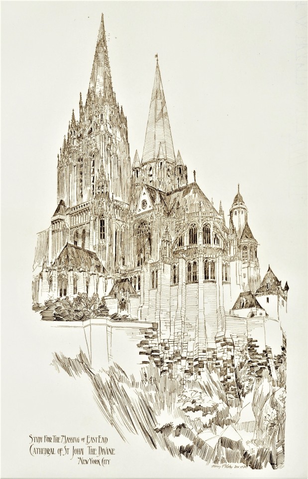
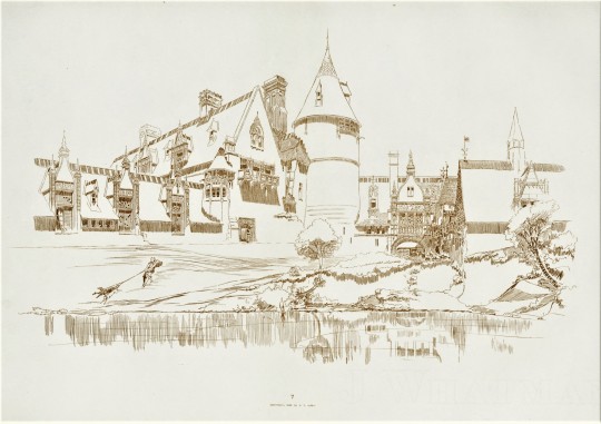
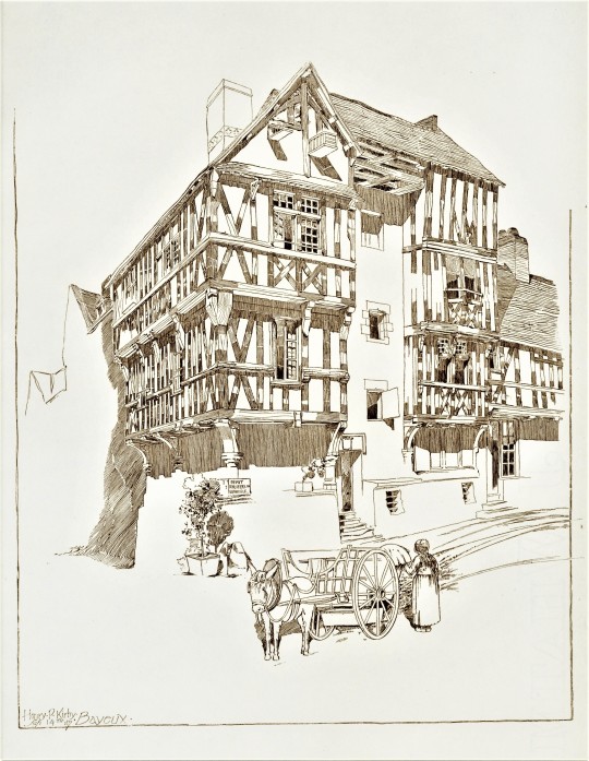
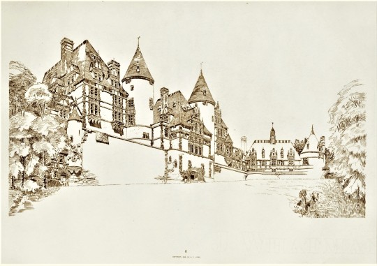
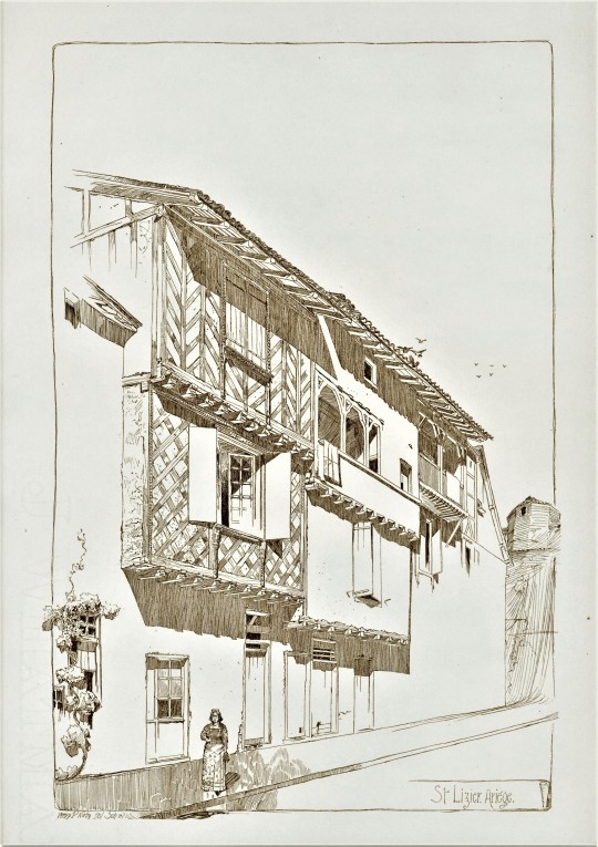

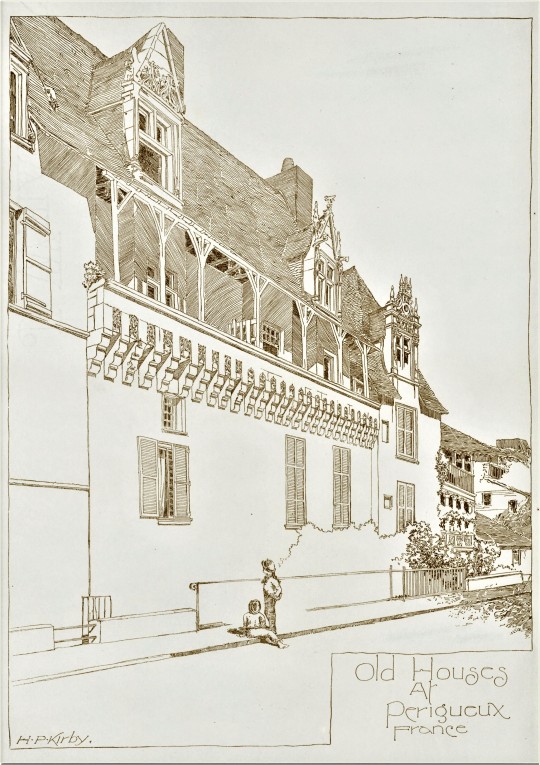
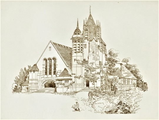
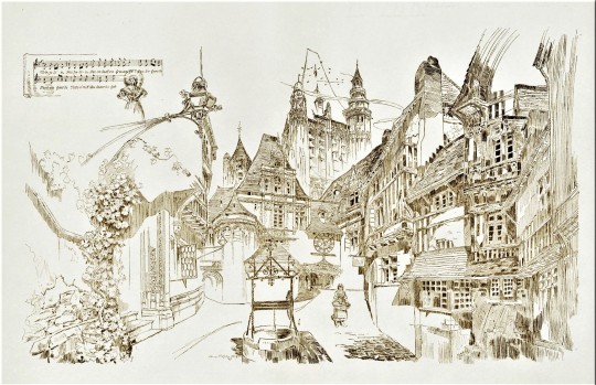
Decorative Sunday with Henry P. Kirby
These charming sketches are the work of New York architect Henry P. Kirby (1853 - 1915). Architectural Compositions contains fifty loose plates printed on Whatman paper and housed in a portfolio. It was published in Boston in 1892 by Bates, Kimball & Guild, publishers of one of the United State’s leading architectural journals of that time, The Architectural Review (Boston), not to be confused with the longer running Architectural Review still in publication out of London.
Kirby would have been working as a draftsman for George B. Post at the time of publication, for whom he later worked as lead designer before striking out on his own. Some of the subject matter also evokes Kirby’s time in France, where he studied at the École des Beaux-Arts after training with his father, also an architect. Per the subtitle, some of the sketches were “made in connection with actual projects,” while many were “the result of study during leisure moments.” I found Kirby’s eye for the human elements in his sketches particularly endearing, from the foreground figures to details on the buildings themselves, like open widows and overgrown foliage, or what looks like a duvet cover hanging out to dry (first image above).
For any music buffs reading, the final sketch includes some bars of "Très-jolie" from the opéra comique smash hit La Fille de Madame Angot.
Our copy of Architectural Compositions was gifted to UWM by Gustav A. Elgeti in 1966.
Find more Decorative Sunday posts here.
-Olivia, Special Collections Graduate Intern
#Decorative Sunday#Architectural Compositions#Henry P. Kirby#Henry Petit & Green#Bates Kimball & Guild#The Architectural Review#George B. Post#École des Beaux-Arts#La Fille de Madame Angot#decorative plates#decorative arts#beaux-arts#architecture#architectural drawings#architectural plates#olivia
433 notes
·
View notes
Text
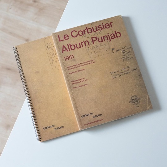

In 1951 Le Corbusier embarked on his „aventure indienne“, his Indian adventure, to design and build Chandigarh, the new capital of the Punjab. On February 20 he boarded a flight to Bombay together with his cousin Pierre Jeanneret and on February 23 the two met up with the players to be involved in the project: Maxwell Fry, engineer P.L. Varma as well as government official P.N. Thapar. At the time of their arrival at the designated site of the future capital it was a wide plain dotted with numerous villages and lush vegetation. On the same day Le Corbusier began writing and drawing in his so-called „Album Punjab“, a notebook he would continue to fill until March 11 and which today represents a unique source to the events, ideas and impressions preceding the design and construction of Chandigarh. The „Album Punjab“ has recently been published for the first time as a facsimile by Lars Müller Publishers and is accompanied by a volume written by Maristella Casciato providing additional context to LC’s commission, unpublished photographs taken by Pierre Jeanneret during the trip and a day-by-day synopsis of the notebook. Already the first entry tells of Corbusier’s deep interest in the existing landscape and villages, their scale and density as well as the daily life going on. At the same time he also began to search for solutions regarding water supply, spatial approaches to climate control and air circulation in residential buildings as well as he sketched a road system for the future capital and its capitol complex. Consecutively Le Corbusier elaborated these initial impressions and sketches and delved into the local architecture, the spatial organization of traditional houses and already drew planimetric arrangements of low-cost housing units. In terms of the overall urban planning LC harked back to the Pilot Plan he developed for Bogotá together with José Luis Sert. A pressing issue that also came up during the trip were construction costs and the high cost of wood which made the use of concrete even more appealing. In view of the far-reaching insights the book provides it is an important addition to the literature on Le Corbusier and highly recommended!
#le corbusier#chandigarh#architectural drawings#architecture book#architectural history#book#modern architecture#lars müller publishers
66 notes
·
View notes
Text
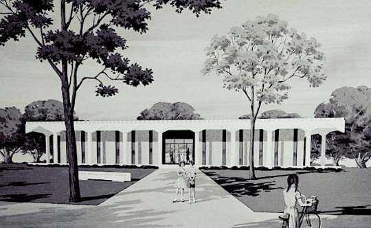
Scenes from home, past and present.
#old new orleans#new orleans#algiers regional library#libraries#architecture#architectural renderings#architectural drawings#modern architecture#mid century modern#mid-century modern#mid-century modern architecture
3 notes
·
View notes
Text
Elevate Your Architectural Projects with Expert Drawing Stamp Services
As an architectural drawing stamp expert with over 13 years of experience, I understand the intricate balance between creativity and compliance in the world of architecture. My journey in this field has equipped me with the skills and knowledge to deliver top-notch architectural and structural designs that not only meet but exceed client expectations.
Why Architectural Drawing Stamps Matter
In the construction and design industry, architectural drawing stamps are essential for ensuring that your projects adhere to local regulations and standards. A properly stamped drawing signifies that a licensed professional has reviewed and approved the plans, providing peace of mind to clients, builders, and regulatory agencies alike. With my expertise, I help streamline the approval process, allowing you to focus on what you do best: creating beautiful spaces.
What I Offer
At my Fiverr gig, I provide a comprehensive range of services tailored to meet your specific architectural needs. Here’s what you can expect:
Professional Stamping of Architectural Drawings: I offer precise and reliable stamping services for various types of architectural and structural drawings, including MEP (Mechanical, Electrical, and Plumbing) and HVAC plans.
Compliance with Local Regulations: With a deep understanding of local building codes and regulations, I ensure that your drawings are compliant, minimizing the risk of costly revisions and delays.
Fast Turnaround Time: I value your time and strive to deliver stamped drawings quickly without compromising quality.
Exceptional Customer Service: My commitment to excellence extends beyond the drawings themselves. I am here to guide you through the process, answer your questions, and ensure a seamless experience from start to finish.
Why Choose Me?
With 13 years of experience in the architectural field, I have successfully collaborated with numerous clients across various projects, from residential homes to commercial buildings. My dedication to quality, attention to detail, and professionalism set me apart in this competitive marketplace.
As a seasoned architectural drawing and structural designer, I bring a unique blend of creativity and technical expertise to every project. I take pride in my work, ensuring that each drawing not only meets regulatory standards but also reflects the vision and style of my clients.
Let’s Work Together!
Ready to elevate your architectural projects? Visit my Fiverr gig to explore my services and see how I can assist you in achieving your design goals. Whether you need a single drawing stamped or a complete set of plans reviewed, I am here to help you every step of the way.
👉 Check out my Fiverr gig here!
Together, we can turn your architectural dreams into reality!
#architecture#structural engineering#architectural stamp#city permits#work permit#2d floor plan#construction#architectural drawings
2 notes
·
View notes
Photo
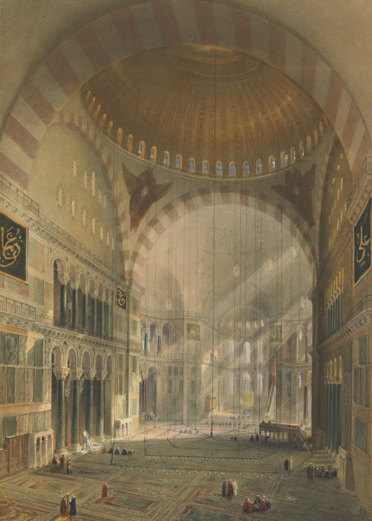
#archival#brown color#architecture#piece of art#artwork#interior#aya sofia#architectural drawings#design drawings#apse#building#church#human
2 notes
·
View notes
Quote
The Manhattan Transcripts differ from most architectural drawings insofar as they are neither real projects nor mere fantasies. They propose to transcribe an architectural interpretation of reality. To this aim, they use a particular structure indicated by photographs that either direct or 'witness' events (some would say 'functions', others would call them 'programs'). At the same time, plans, sections, and diagrams outline spaces and indicate the movements of the different protagonists – those people intruding into the architectural 'stage set'. The effect is not unlike an Eisenstein film script or some Moholy-Nagy stage directions. Even if the Transcripts become a self-contained set of drawings, with its own internal coherence, they are first a device. Their explicit purpose is to transcribe things normally removed from conventional architectural representation, namely the complex relationship between spaces and their use; between the set and the script; between 'type' and 'program'; between objects and events. Their implicit purpose has to do with the twentieth-century city.
Bernard Tschumi, The Manhattan Transcripts
#quote#Bernard Tschumi#Tschumi#The Manhattan Transcripts#architecture#architectural theory#film#stage#film theory#architectural drawings#Manhattan#urban planning#city planning#urban design#Eisenstein#Sergei Eisenstein#László Moholy-Nagy#Moholy-Nagy
22 notes
·
View notes
Text
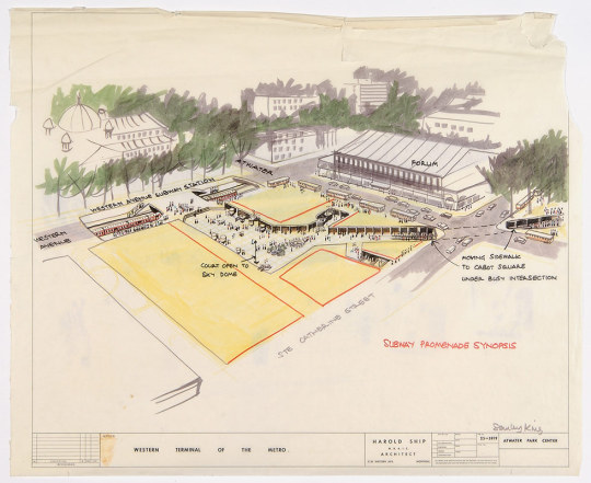
Plaza Alexis Nihon Traffic study for the promenade on the Atwater metro station level. Stanley King, Draughtsman; Harold Ship, Architect. 1964 [City of Montreal Archives]
11 notes
·
View notes
Text
0 notes
Photo


Art by Min.K Shin
7K notes
·
View notes
Text
Why Construction Drawing is Essential for Obtaining Building Permits?
Construction drawings are crucial for ensuring that the building is constructed according to the intended design and meets all relevant codes and standards.
#construction drawing#building permits#drafting plans#architectural drawings#structural drawings#civil drawings#building permit approvals
0 notes
Text
What are Construction Drawings (CD Sets) in Construction?

Construction drawings, also known as CD sets or working drawings, are prepared by architects to visualize the design of a structure before construction begins. These 2D documents, including architectural and structural drawings, help communicate the design intent, materials, and specifications to the construction team.
These drawings are crucial for contractors to understand the project's details, such as the structural use, appearance, materials, and connections between building components. Often referred to as IFC (Issued for Construction) drawings, they serve as a guide during the building process.
However, construction drawings may contain errors or ambiguities since they are created before fieldwork begins. To address this, they are often marked with "Verify-in-Field" labels to confirm measurements on-site.
The details included in these drawings cover various aspects of the project, such as interior and exterior elevations, framing and utility plans, sections, and schedules for doors, windows, and finishes. They also include essential MEP (Mechanical, Electrical, and Plumbing) information, which ensures the smooth integration of different building systems.
In summary, construction drawings are vital in estimating labor, materials, and costs, allowing contractors to plan effectively while offering a detailed roadmap for the successful execution of a construction project.
#construction drawings#construction documents#architectural drawings#2d drawings#construction#residential#building drawings
1 note
·
View note
Text


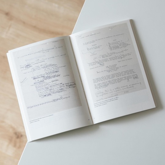
Some 50 years ago, on March 17, 1974, Louis Kahn passed away at Penn Station at a time when his office was buzzing with significant projects: the Franklin Delano Roosevelt Memorial, the Yale Center for British Art and the urban development of Abbasabad, a new district in Tehran, Iran, to be developed in collaboration with Kenzo Tange. Of these projects the Roosevelt Memorial was of the greatest significance for Kahn because he personally benefited from the president’s „New Deal“ policy of the 1930s and was thus highly motivated to design the memorial. Hence it is no wonder that he worked quite fervently on it as shows the notebook he filled with numerous drawings and variants of the project until his untimely death.
This last notebook of Louis Kahn, which he began in late February/early March 1973, has recently been published by Lars Muller Publishers as a facsimile, edited by the architect’s daughter Sue Ann Kahn and supplemented with a separate volume containing an essay by Michael J. Lewis.
Kahn was an accomplished draftsman who drew passionately and developed projects in his notebook first: in sometimes thumbnail-sized drawings the notebook documents the progress of the projects but also contains notes and addresses Kahn wrote down during meetings and events. In contrast to these quickly taken notes several of the drawings are carefully colored.
Beyond drawings the notebook also contains the outlines of two public lectures he gave in October 1973, one being the Tiffany Lecture at the University of Pennsylvania and the other his principal address delivered during the dedication of the new architecture building of the University of Maryland that coincided with the award of an honorary degree to Kahn himself. For each he merely laid down some key aspects he wished to address instead of formulating a complete text: in both Kahn dealt with the relationship between form and design but for the second occasion he outlined his speech in a visual manner to have it projected during his speech.
This workbook character is faithfully reproduced by the facsimile and once more proves the importance of drawing(s) for Louis Kahn’s creative process. A beautiful gem!
#louis kahn#architectural drawings#notebook#lars muller publishers#architectural history#architecture book#book
30 notes
·
View notes
Text

Scenes from home, past and present.
#old new orleans#new orleans#algiers regional library#libraries#architecture#architectural renderings#architectural drawings#modern architecture#mid century modern#mid-century modern#mid-century modern architecture
2 notes
·
View notes
Text
All you need to know about Essential Drawings for Building Design

Architectural design is a dynamic field that blends creativity with precision. To bring a building from concept to reality, various drawings play a critical role. These drawings are the blueprints of any construction project, guiding every step from planning to execution. Understanding the different types of drawings used in building design is essential for architects, engineers, and construction professionals.
This guide covers the essential drawings used in building design, including architectural, structural, mechanical, electrical, and plumbing drawings. Learn how each type contributes to the overall success of a construction project.
1. Architectural Drawings
What Are Architectural Drawings?
Architectural drawings are the primary tools used by architects to convey their vision. These drawings include floor plans, elevations, and sections, detailing every aspect of the building’s design.
Types of Architectural Drawings
Floor Plans: Show the layout of rooms and spaces from a top-down view.
Elevations: Depict the exterior faces of the building.
Sections: Provide a vertical cut-through view of the building.
Importance of Architectural Drawings
Architectural drawings ensure that the design intent is communicated clearly to all stakeholders, including clients, contractors, and regulatory bodies.
2. Structural Drawings
What Are Structural Drawings?
Structural drawings provide detailed information about the load-bearing elements of a building. These drawings are essential for ensuring the building’s stability and safety.
Types of Structural Drawings
Foundation Plans: Show the layout and details of the building’s foundation.
Framing Plans: Detail the construction of floors, walls, and roofs.
Detail Drawings: Provide specific information on joints, beams, and columns.
Importance of Structural Drawings
Structural drawings are crucial for guiding the construction of a safe and stable structure. They ensure that the building can withstand various loads and stresses.
3. Mechanical Drawings
What Are Mechanical Drawings?
Mechanical drawings illustrate the building’s mechanical systems, such as HVAC (heating, ventilation, and air conditioning). These drawings are essential for ensuring the comfort and efficiency of the building’s interior environment.
Types of Mechanical Drawings
HVAC Plans: Show the layout of heating, ventilation, and air conditioning systems.
Ductwork Drawings: Detail the pathways for air distribution.
Equipment Schedules: List the specifications for mechanical equipment.
Importance of Mechanical Drawings
Mechanical drawings ensure that the building’s HVAC systems are designed and installed correctly, contributing to the overall comfort and energy efficiency of the building.
4. Electrical Drawings
What Are Electrical Drawings?
Electrical drawings provide detailed information about the building’s electrical systems, including power distribution, lighting, and communication systems.
Types of Electrical Drawings
Power Plans: Show the layout of electrical circuits and outlets.
Lighting Plans: Detail the placement and type of lighting fixtures.
Riser Diagrams: Illustrate the vertical distribution of electrical systems.
Importance of Electrical Drawings
Electrical drawings are essential for ensuring that the building’s electrical systems are safe, efficient, and comply with regulations.
5. Plumbing Drawings
What Are Plumbing Drawings?
Plumbing drawings illustrate the building’s plumbing systems, including water supply, drainage, and waste systems. These drawings are vital for ensuring proper sanitation and water management.
Types of Plumbing Drawings
Water Supply Plans: Show the layout of pipes for hot and cold water.
Drainage Plans: Detail the pathways for wastewater and rainwater.
Fixture Schedules: List the specifications for plumbing fixtures.
Importance of Plumbing Drawings
Plumbing drawings ensure that the building’s water systems are designed and installed correctly, preventing issues such as leaks and blockages.
By mastering the different types of drawings used in building design, architects, engineers, and construction professionals can collaborate effectively and create buildings that are not only aesthetically pleasing but also structurally sound and efficient.
Conclusion
An integral part of this process is precise CAD drafting, which serves as the backbone of accurate and efficient project execution. Shalin Designs offers comprehensive CAD drafting services that cater to all aspects of building design, ensuring each drawing type is meticulously crafted to enhance the project’s overall quality and coherence. Their expertise in creating detailed and reliable CAD drawings significantly aids in minimizing errors and streamlining the construction process.
Ready to take your building design skills to the next level? Contact Shalin Designs today to learn how our expert CAD services can bring your project to life. Whether you need detailed architectural drawings or comprehensive structural plans, our team is here to help you achieve excellence in every aspect of your construction project. Let’s build something amazing together!
#Architectural Drawings#Structural Drawings#Mechanical Drawings#Electrical Drawings#Plumbing Drawing#CAD Drawings#Shalin Designs
0 notes
Text


Express your love for architecture with our eye-catching stickers, notebooks, prints and more featuring intricate details like arches and columns. Shop now!
#architectural quotes#findyourthing#redbubble#gift for her#gift for him#interior design#interiors#architecture school#architecture design#future architecture#future architect#home design#home decor#gift ideas#home decorating#luxury home architects#office decor#office design#architectural photography#urban landscapes#modern architecture#building#motivational quotes#architectural aesthetics#architectural masterpieces#architectural illustrations#architectural drawings#architectural wonders#architectural beauty#landscape architect
0 notes
Text
019. Artists' House and Studio
An artist couple wanted us to complete their ongoing project, of which the footing and column rebaring was completed. The project had already changed hands with a few architects. The program changed from a simple art gallery in the suburbs to a gallery, studio, and a complete family house, during the process of construction. A new staircase is being proposed while we make this post. Our��

View On WordPress
#2022#2023#2024#architectural design#architectural drawings#architecture#Architecture in india#artists house#Belagavi#belgaum#form#karnataka#roomforarchitecture
1 note
·
View note