#seeed studio
Explore tagged Tumblr posts
Text


Not sure the best way to get these all out, so going to do one big post... We're getting the word out about sales, deals, and more for other maker companies - we have nothing to do with these sales, this is not sponsored in any way, we're posting them up for our followers, fans, and more! Post up ones you've found with #makerdeals
Particle - Spend $100, get $25 more and free shipping! https://store.particle.io/collections/holiday-sale
=========
Tindie Cyber Monday Sale! "Buy awesome things directly from makers" https://www.tindie.com/browse/sale/
===========
Buy a Bantam Tools NextDraw™ 1117 get a Tool Holder Bundle for Free! https://store.bantamtools.com/products/bantam-tools-nextdraw-1117-bundle
===========
Pimoroni - Choose from 1,000+ great discounts, also have an annual set of #yarrbooty challenges on BlueSky. https://shop.pimoroni.com/pages/yarrbooty-2024
===========
Pololu - Discounts on 1,402 of their top products. To access the discounts, you must add the coupons to your cart along with the items you want to purchase https://www.pololu.com/blackfriday2024
===========
Teensy Sale 2024, heavily discounted Teensy 4, audio shield, pin headers/sockets https://www.pjrc.com/store/blackfriday2024.html
===========
Seeed Studio - Special offers, buy 2 get 1 free on selected products, and $5 coupon for new customers - https://www.seeedstudio.com/thanksgiving-2024
===========
DigiKey - #DigiWish Make a Wish! 1) Choose one in-stock DigiKey product valued at US $100 or less. 2) Share your wish with us via a comment or a post using the hashtag #DigiWish. 2) Check in each day to see if your wish came true. https://www.digikey.com/en/resources/social/digi-wish/
4 notes
·
View notes
Text
USB-BLE MIDIインターフェイスを作る - 環境構築編
1000円ちょっとでUSB-BLE MIDIインターフェイスを作ってみようという話です。
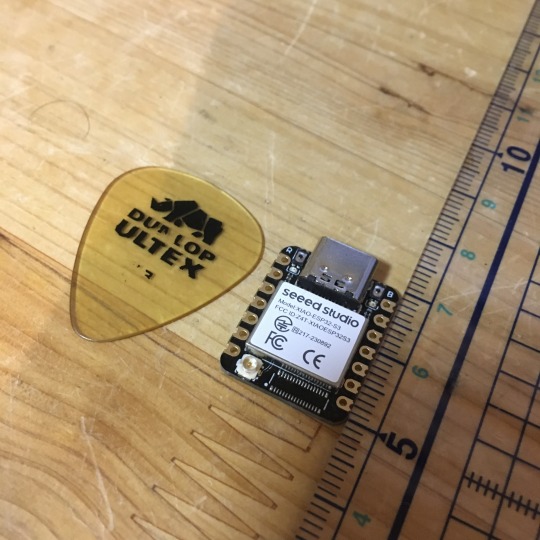
最近Bluetooth LE(BLE)を使って無線でMIDI信号をやり取りするのが流行ってますね。しかし、WindowsではBLE MIDIの対応があまりよろしくなく、Bluetoothが使えるPCでもBLE MIDIを使うのは難儀な感じです。ということで、いわゆるMIDI端子に接続して無線化するBLE MIDIインターフェイスを買うかな……と思っていたわけですが、そんな折ふとワイヤレスMIDI製品で知られるQUICCO SOUNDの通販サイトを見てみたらBluetooth MIDI基板なるものが。
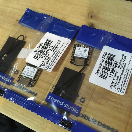
これ、小型IoTボードのSeeed Studio XIAOシリーズに似ているよなあ、XIAOシリーズはBLE対応しているし、USBポートも搭載されているからこれでUSB-BLE MIDIインターフェイスを作れるのでは? と思い立ち、早速秋葉原でボード2種類を買ってきました。
XIAOシリーズには複数の製品ラインアップがあるのですが、そのなかでも安いのが「ESP32C3」というモデル(税込940円)と、「ESP32S3」というモデルです(税込み1,150円)。
軽くネットで調べたところ、どちらも少なくとも公開されているBLE MIDIライブラリには対応しているようでした。また、USB MIDIに関しては、少なくともESP32S3についてはネットでUSB MIDIデバイス化させている記事(「蛇腹楽器型MIDIコントローラーV2 ~ USB MIDIデバイスの作り方」)がありました。
ということで、とりあえずESP32S3で試してみましょう。
開発環境を整備する
Seeed StudioのXIAOシリーズはArduino IDEで開発やプログラム書き込みが行えるのですが、そのためにはArduino IDEに追加のライブラリやボード情報をインストールする必要があります。設定方法はSeeed StudioのWebサイトに詳しく書かれているので、この手順通りボードマネージャURLの追加���行えばOKです。
USB MIDIやBLE MIDIに関しては、Arduino MIDI Libraryと組み合わせて利用できるライブラリが公開されており、これを導入することで簡単に利用できるようになるようです。いくつか選択肢もあるようですが、今回は次の3つを導入しました。いずれもArduino IDEのライブラリマネージャからインストール可能です。
Adafruit TinyUSB Library
Arduino BLE-MIDI Transport
NimBLE-Arduino
動作テスト用コードの実装
まずはこれで本当にUSB MIDIデバイスやBLE MIDIデバイスとして動作するのかを検証するため、MIDIのnote on/note offメッセージだけをやり取りするコードを書いてみます。前出の「蛇腹楽器型MIDIコントローラーV2 ~ USB MIDIデバイスの作り方」や、「NimBLE + BLE MIDIで音を出した」、「M5StickC で、BLE-MIDI ドラム」などを参考に、こんな感じでコードを書いてみました。

やっている処理は
各インターフェイスの初期化
BLE MIDI側で受け取ったnote on/offメッセージをそのままUSB MIDI側に送信
USB MIDI側で受け取ったnote on/offメッセージをそのままBLE MIDI側に送信
の3つだけです。BLE MIDIの接続時にLEDを光らせる部分のコードはそのままコピペしたのですがコンパイルエラーになったのでとりあえずコメントアウトしています。
ビルドと書き込み
ボード設定は��んな感じです。
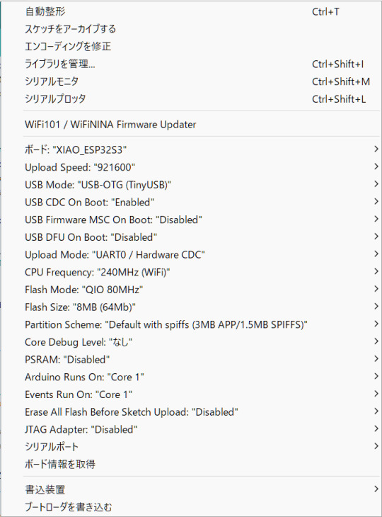
ボードとして「XIAO_ESP32S3」を選択し、それに加えてUSB Modeとして「USB-OTG (TinyUSB)」を選択しておく必要があります。また、色々とライブラリを使用しているためかArduino IDEがOutOfMemoryでフリーズしたので、前回記事で紹介したArduino IDEのメモリ設定の変更も行っています。
書き込み自体はボードをUSBでPCに接続し、シリアルポートを適切に選択して書き込みを実行するだけ行えます。念のため書き込み後はいったんUSBケーブルをポートから取り外して、再度USBポートに差し込んで再起動させています。
動かしてみる
BLE MIDI対応デバイスと言えばiPhoneやiPadですね。ということで、PC上のAbleton LiveからMIDI信号を送ってiPad上のGarageBandを鳴らしてみました。Ableton Liveからは問題なくUSBデバイスとして認識され、またiPadからも問題なくBLE MIDIデバイスとして認識されました。MIDIノートの送信もできています。
ただ、若干発音タイミングがヨレています。このあたりは改善したいところですが、果たしてできるのでしょうか?
(続く)
5 notes
·
View notes
Text
Seeed Studio debuts Raspberry Pi 5 PCIe 3.0 HAT with dual M.2 slots for $45
Earlier this week, a remarkable Raspberry PI 5 PCIe HAT -level PCIe HAT board was released, supporting the PCIe 3.0 standard instead of PCIe 2.0, as well as providing two M.2 slots. Seed Studio PCIe 3.0 for Dual M.2 Hat [h/t CNX] It costs only $ 45 for the official page of the store. For this price, you get one PCIe 3.0 line for each M.2 slot with a 8 GT/s bandwidth for both slots. In addition to…
0 notes
Video
youtube
2pcs/1pc Seeeduino XIAO BLE SENSE seeed studio XIAO RP2040 nRF52840 Blue...
#youtube#xiao nrf52840 ble#nrf52840 long range#nrf52810#intel x540 nic#super mini nrf52840 vs nice nano#xiao esp32 s3 sense#x540n battery#bf 528#seeed xiao nrf52840#xiao nrf52840
0 notes
Text
Meshtastic Kit for Experimentation
Die Seeed Studio XIAO-Serie ist eine Familie kompakter, leistungsstarker Mikrocontroller-Module (MCU), die speziell für platzsparende Projekte entwickelt wurden, die hohe Leistung und drahtlose Konnektivität erfordern. Die Arduino-kompatible XIAO-Familie stellt Mikrocontroller-Module auf Basis verbreiteter Hardware wie Espressif ESP32-C3, ESP32-C6 & ESP32-S3, Renesas RA4M1, Raspberry Pi RP2350 &…

View On WordPress
0 notes
Text
Open Roberta #6 - Grove Drehpotentiometer

In diesem Beitrag möchte ich dir das Grove Drehpotentiometer Modul vorstellen und zeigen wie dieses am Arduino UNO mit Open Roberta programmiert wird.

Im letzten Beitrag Open Roberta #4 – Grove LED hatte ich dir bereits gezeigt, wie du eine Leuchtdiode mit einer Schleife Auf-/Ableuchten lassen kannst, in einem weiteren Beispiel werde ich dir zeigen, wie du dieses mit einem Drehpotentiometer lösen kannst.
Benötigte Ressourcen für den Nachbau der Schaltungen
Wenn du die Schaltungen nachbauen möchtest, dann benötigst du: - einen Arduino UNO, - ein USB-Datenkabel, - ein Base Shield v2 für den Arduino UNO, - ein Grove Drehpotentiometer Modul, - ein Grove LED Shield, - zwei Grove Verbindungskabel

Bauteile für die Schaltung - Grove Drehpotentiometer am Arduino UNO
Aufbau des Grove Drehpotentiometer Shields
Das mir vorliegende Modul / Shield hat einen 10 kOhm Drehpotentiometer verbaut und nachfolgenden Aufbau.

Aufbau - Grove Drehpotentiometer Auf der Rückseite findest du die Pin Beschriftungen, an diesen kannst du zusätzlich erkennen welches Datenkabel mit dem Arduino verbunden wird. Das Gute an den Grove Verbindungen ist, dass diese nur in eine Richtung korrekt eingesteckt werden können. Des Weiteren sind die Kabel bereits farbig gekennzeichnet, somit erkennst du die Spannungsversorgung (Schwarz - GND, Rot - VCC) sowie die Datenleitungen (Weiß & Gelb).

Grove Connector mit Stecker
Technische Daten
Von der offiziellen Wiki-Seite des Herstellers seeed studio konnte ich noch zusätzliche technische Daten entnehmen. Betriebsspannung4,75 V bis 5,25 VDrehwinkel0° bis 300°Abmessungen19 mm x 19 mm x 30,1 mm
Aufbau der Schaltung am Arduino UNO
Mit dem Base Shield v2 und den Grove Verbindungen ist der Aufbau der Schaltung sehr schnell und gerade für Anfänger sehr sicher aufgebaut. Man muss lediglich darauf achten, dass der Drehpotentiometer an einen analogen Pin und das Grove LED Shield an einen digitalen PWM Pin angeschlossen wird. Die PWM Pins liegen beim Arduino UNO an D3, D5, D6, D9, D10, D11.

In meinem Fall habe ich die Bauteile wie folgt an den Arduino UNO angeschlossen: BauteilArduino UNOLEDD3DrehpotentiometerA0
Aufbau der Schaltung & programmieren in Open Roberta
Im nachfolgenden YouTube-Video zeige ich dir, wie du die kleine Schaltung aufbaust, mit der du mit einem Drehpotentiometer die Helligkeit einer LED steuern kannst und das Ganze im Open Roberta Lab programmierst. https://youtu.be/R3SXFCYuC3o
Programmieren in Open Roberta
Zunächst müssen wir in dem Reiter "ROBOTERKONFIGURATION" die erzeugte Schaltung nachbauen.

Ein Drehpotentiometer ist ein einfacher analoger Sensor, welcher über einen variablen Widerstand verfügt. Den Wert können wir über das Rädchen einstellen, je nachdem wie die Spannungsversorgung angelegt ist, sind die Werte auf oder absteigend. Mappen von Werten in Open Roberta Der Drehpotentiometer wird wie erwähnt an einen analogen Pin angeschlossen und liefert Werte zwischen 0..1023. Wie du diese Werte nun auf ein PWM Signal mappen kannst, habe ich dir bereits im Beitrag Open Roberta Lab - analoges Signal auf PWM mappen erläutert.

Download
Hier jetzt der Code zum bequemen download. Grove Drehpotentiometer - LED per PWM Signal steuernHerunterladen Read the full article
0 notes
Photo

Seeed Studio Offers Meshtastic Support in Its Latest Wio Tracker 1110 Update
0 notes
Text
I need to dig out the cheap little General MIDI ROMpler I have tucked away that has a MIDI Thru on it, because I got interesting results out of playing with something else entirely. See, what I was just playing with is one of my very early DIY synth experiments, which I think I called WaxSynth.
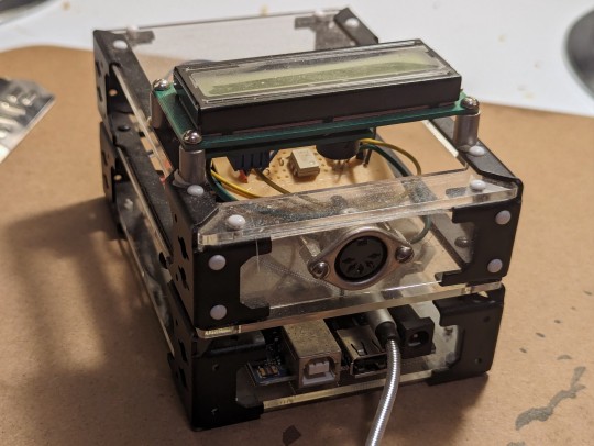
This guy is an Arduino Mega 2560 ADK with a Seeed Studio Music Shield, a MIDI input circuit on protoboard, and a serial LCD display, all put together in a skeletal case system that Radio Shack sold back in the day. The Music Shield is built around the VS1053 audio chip, which is primarily meant to play MP3s but does have a built-in General MIDI synth; you can either throw MIDI files at it or send it real-time MIDI commands, which is what I'm doing here. It's set up so you just plug a keyboard into the MIDI jack, plug it into power, and it'll play audio out the audio jack (the one with the cable plugged in). You can change the instrument either by MIDI commands or via the rocker switch recessed into the left side; the name of the instrument is displayed on the LCD. The patches are generally cheap sounding, but it was pretty amazing to be able to put this together and get it to work all those years ago.
I was looking at this tonight and decided to plug it into my modular synthesizer and play it through different things, and after appropriate boosting of the level, a number of different patches worked. What worked best was running the audio from this into the Hard Sync on my VCO and coercing it into changing a simple monosynth drone into glitchy piano, horn, and organ tones, and even chords, which I did not expect to get out of just sync. The only drawback is of course that once the little MIDI synth stops playing, the drone reasserts itself, and the harmonic clashes are kinda bothersome.
Which is why I need to use the ROMpler with MIDI Thru instead of this guy. I could then also run the same MIDI signal into my Breakout MIDI to CV converter to get note event gates, and use an envelope and VCA to only play the notes while the keys are pressed. I'll try to make a demo recording once I do.
0 notes
Text
This project is by far the one I'm most proud of. I've learned so many new skills, from PCB design, to stencil SMD soldering, to using multi core threading on the processor (a Seeed Studio Xiao ESP32S3) and building wifi managers, and there's still so much more to do before I release it into the wild

0 notes
Text
0 notes
Text
Arduino Sensor Kit in Partnership with Seeed Studio
youtube
0 notes
Text
NRF52840 Xiao Sense
Happy Manic Maker Monday!
For two upcoming projects, I'm going to be using two flavors of the Seeed Studios Xiao boards based on the NRF52840. These little boards are really something.
For one upcoming project, it has one of each of the exact things I need:
BLE to connect to another project on which I'm working
UART for chatpad input
SPI for eink display
I2C for a GPS
A few GPIO for a soft power button, an indicator LED, and maybe a vibration motor for haptics
Battery power and charging
An internal IMU (on the Sense flavor)
The only difference between the Sense and the non-Sense is that the former has a built-in IMU and microphone which are meant for tinyML projects since ML is all the rage (think of being in ultra-low power and performing inferences on audio samples but sleeping and collecting in-between).
In fact, for this Learn-a-Thon, there are a few things I totally want to investigate: the Embedded Template Library (for exploration on C++ to really object-orient the project), nRF Connect SDK, Zephyr OS (I'm late to jump on the bus here but there's good talk about this Linux-like take on RTOS), BLE, and TinyML.
nRF Connect SDK - It will be nice to get into the APIs provided by Nordic without any layers inbetween. A simple bare-metal eventloop will be lovely here.
ZephyrOS - I'll probably only be using this one of the projects since for the other one, bare metal will be just fine and I'd like to just get into the direct nRF Connect SDK for the hell of it. They say this abstracts away drivers which is an interesting prospect included in an RTOS! I've heard it's 80% configuration and 20% coding but, if it's good code running the drivers, why not just leverage it!
Embedded Template Library - generally I don't code in C++ besides for work, but I love the idea that it is possible to code something that uses primarily static data and has a low footprint. I've read reviews on ETL, heard about it on podcasts, and just gotta try it. There is a solid reason for using C++ in these projects and that is that I want to create a common base class that outlines capabilities of each of these devices.
BLE - I've done lots with wifi, written wifi drivers, wifi managers, connectivity managers, etc, but never BLE! I totally feel like I need to try it out! Especially since one of the projects is purely a sensor arm that transmits over BLE. Eventually, something else that would be really interesting would be OTA over BLE which I've never had to manage.
TinyML - I also haven't jumped into the ML/AI with both feet really. I've used pre-compiled models and hardware acceleration and some tangential TVM stuff but I want to create the model and see it with my own destructive hands >:) I'm also interested how much optimization is in control of the model developer.
Low Power Mode - I've done some of this already at work but it's a good idea to get in the weeds on a different micro. Especially, I'd like to understand how Zephyr might abstract this, how I can optimize packet offloads, etc.
I've got kind of a slew of experiments I want to try:
Zephyr OS Emulation - No hardware way to get started upper level programming. I would love to code around in Zephyr and get emulated results. Always a handy tool.
Zephyr OS - Get hello world on Xiao (sanity, familiarity, etc)
Zephyr OS + BLE - I've seen demos, I think it's easy to get started. Attaching a button or sensor should be pretty easy from there.
TinyML + IMU + BLE (https://blog.tensorflow.org/2021/05/building-tinyml-application-with-tf-micro-and-sensiml.html)
0 notes
Text
0 notes
Link
0 notes
Text
Returning to Z80
It dawned on me a few days ago that I have a Seeed Studio TFT shield for Arduino that uses a controller with 8-bit 8080-compatible interface and has built-in pixel memory ... Meaning it should be easy enough to drive it from my breadboard Z80 computer, and I wouldn't have to keep the entire display in RAM (since 320x240 > 64k). I've spent what time I could spare over the last few days porting the sTFT Arduino C++ library to something that would compile with SDCC for Z80. It's a simple library, and the interfacing is actually easier on Z80 than AVR because I can just use the OUT instruction instead of manually strobing GPIOs. I pulled out the breadboard tonight to see how far I could get in testing. I've not touched it since January, and worse I've moved since then. Storage has not been kind to my little computer. It was carefully wrapped in anti-static bubble wrap, and nothing seems out of place, but it gives no immediate signs of life. Logic probe sings, so I know it's doing something. I pulled out out my cheap logic analyzer, and I was able to trace the data bus all the way through initializing the SCC (Serial Communications Controller, Zilog Z85C30) chip and into the first printf() call, but terminal never prints anything. Best I get is what appears to be randomly spaced 0x0D output on TxDA. That SCC is a fickle beast. It's a great chip with a lot of features for its time, but it is always a pain to get up and running. Here, since SCC is the first thing initialized by my monitor code, and my putchar() function is blocking, the program never moves on. It just sits in a tight loop, waiting for confirmation from the SCC that it's ready to transmit. Hopefully I can figure out the problem with the SCC without too much trouble. I really don't want to have to start over just to test the LCD shield. And perhaps I should add some blinkenlights so it's obvious the computer is doing something, without having to pull out the probes.
5 notes
·
View notes
Text
Grove 8x8 LED Matrix am Arduino: Einsteigerfreundliche Programmieranleitung
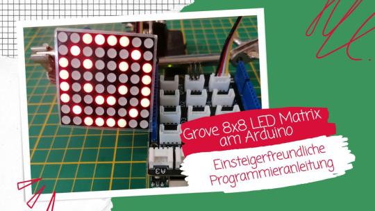
In diesem Beitrag möchte ich dir zeigen, wie du die Grove 8x8 LED Matrix am Arduino UNO R3 programmierst. Der Vorteil von diesem Modul ist es, dass du keine umständliche Verkabelung vornehmen musst, da die Grove Schnittstelle einheitlich ist und ein vorkonfektioniertes Kabel verwendet wird.
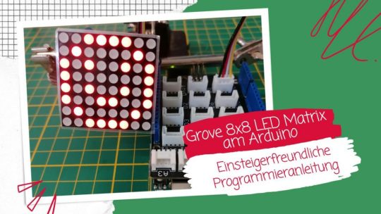
Grove 8x8 LED Matrix am Arduino: Einsteigerfreundliche Programmieranleitung Im Beitrag Arduino Lektion 8: Max7219 8×8 LED Shield habe ich dir bereits ein ähnliches Modul mit dem Chip MAX7219 vorgestellt. Hier soll es nun um eine Matrix mit dem Treiber HT16K33 gehen.

Bezug einer 8x8 LED Matrix mit Grove Schnittstelle
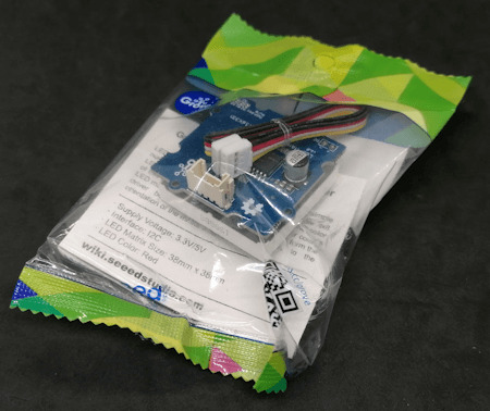
Das mir vorliegende Modul habe ich auf ebay.de für rund 9 € zzgl. Versandkosten erstanden. Du bekommst dieses Modul aber etwas günstiger bei BerryBase für derzeit 8 € zzgl. Versandkosten. Lieferumfang Im Lieferumfang der LED Matrix ist neben der Matrix noch ein kleines Grove Kabel für den Anschluss, sowie ein Zettel mit den wichtigsten technischen Daten.

Auf der LED Matrix ist noch eine kleine Schutzfolie, welche du abziehen kannst, ich lasse diese jedoch drauf.
Aufbau der 8x8 LED Matrix
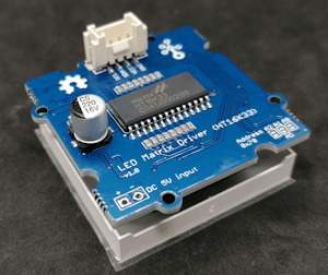
Auf der Rückseite findest du die Grove Schnittstelle, sowie zwei Lötpunkte für die optionale externe Stromversorgung. Des Weiteren kannst du die I2C Adresse 0x70 via 3 Lötbrücken ändern.

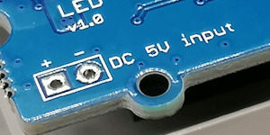

I2C Adressen via Lötbrücken Wenn du die Lötbrücken verbindest, dann kannst du diese Matrix über nachfolgende I2C Adressen ansteuern. Dabei kannst du auch mehrere Muster wählen und so zwischen 8 I2C Adressen auswählen. Verbundene PinsI2C Adresse-0x70A00x71A10x72A20x72A0 & A10x73A0 & A20x75A1 & A20x76A0, A1 & A20x77 Zur Ermittlung der I2C Adressen habe ich den I2C Scanner von https://playground.arduino.cc/Main/I2cScanner/ verwendet.
Zusätzliche Ressourcen für die Programmierung am Arduino
Damit du diese LED Matrix programmieren kannst, benötigst du entweder - ein Grove Adapterkabel, oder - ein Grove Base Shield für den Arduino UNO R3, oder - ein Seeeduino Nano
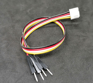
Grove Adapterkabel zu Breadboardpins

Grove Base Shield für den Arduino UNO R3
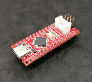
Seeeduino Nano Das Grove Base Shield hat mehrere Grove Buchsen digital & analog und somit bietet dieses eine sehr große Bandbreite an Möglichkeiten für Projekte. Wenn du lediglich die LED Matrix programmieren möchtest und du hast bereits einen Arduino Nano oder Arduino UNO dann
Programmieren der LED Matrix am Arduino via I2C
Damit die LED Matrix mit HT16K33 Treiber angesteuert werden kann, müssen wir in der Arduino IDE eine zusätzliche Bibliothek installieren. Diese können wir uns als ZIP-Datei vom GitHub Repository Seeed-Studio/Grove_LED_Matrix_Driver_HT16K33 herunterladen. Weitere Informationen zu diesem Modul findest du auf der englischen Wikiseite von Seeedstudio https://wiki.seeedstudio.com/Grove-LED_Matrix_Driver-HT16K33/. Anzeigen eines Smileys auf der LED Matrix Für die Erstellung eines Smileys kannst du den LED Matrix Editor unter https://xantorohara.github.io/led-matrix-editor/ verwenden. Dieser Onlineeditor gibt dir die Möglichkeit, mit der Maus auf der LED Matrix einzelne LEDs zu aktivieren / deaktivieren.
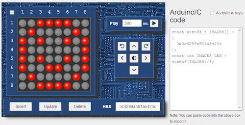
LED Matrix Editor von Xantorohara Auf der rechten Seite findest du ein Stück Code, welchen du in dein Arduino Programm integrieren kannst. In meinem Fall habe ich ein lachendes Smiley gezeichnet und erhalte den Wert "0x3c4299a581a5423c". Die Bibliothek liefert zusätzlich ein paar Beispiele, welche mit der default I2C Adresse 0x70 lauffähig sind. Von diesen Beispielen wähle ich zunächst "displaycustom_pictures" und modifiziere dieses etwas. //Bibliotheken zum kommunizieren mit der LED Matrix #include #include "Grove_LED_Matrix_Driver_HT16K33.h" //Wert für ein lachenden Smiley const uint64_t smiley = 0x3c4299a581a5423c; //instanz einer LED Matrix Matrix_8x8 matrix; void setup() { //beginn der I2C kommunikation Wire.begin(); //beginn der kommunikation mit der LED Matrix matrix.init(); //setzen der Helligkeit der Matrix //Werte sind zwischen 0 und 15 //wobei 0 dunkel ist und 15 das hellste matrix.setBrightness(5); //In welcher Frequenz die LED Matrix blinken soll, //Werte sind: //- BLINK_OFF > kein blinken, //- BLINK_1HZ > langsames blinken, //- BLINK_2HZ > schnelles blinken, matrix.setBlinkRate(BLINK_OFF); } void loop() { //anzeigen eines Bildes matrix.writeOnePicture(smiley); //absenden der Daten matrix.display(); //eine Pause von 10 Sekunden delay(10000); } Auf der Matrix hat man natürlich nur begrenzte Möglichkeiten zur Darstellung von Bildern, jedoch für so kleine Smileys und Pfeile ist dieses bestens geeignet.

lachender Smiley auf der 8x8 LED Matrix Ausgabe von Scrolltext auf der LED Matrix Da wie erwähnt die kleine LED Matrix nur begrenzten Platz für Zeichen bietet, gibt es die Möglichkeit Text auf diesem durchscrollen zu lassen. void loop() { //Funktion zum anzeigen eines Textes auf der LED Matrix, //Parameter: //String - die Zeichenkette welche ausgegeben werden soll, //Zahl - Wert in Millisekunden pro Zeichen //Typ //ACTION_SHIFT - jedes Zeichen einzeln anzeigen, //ACTION_SCROLLING - den Text durch die Matrix scrollen lassen matrix.writeString("Hallo Welt!", 1000, ACTION_SCROLLING); matrix.display(); } Damit ich das Video aufnehmen konnte, sodass meine Kamera den Text erfasst, habe ich ein kleines Tuch vor die LED Matrix gehängt.
Ändern der default I2C Adresse im Programm
Wenn du bereits Sensoren oder Aktoren am I2C Bus angeschlossen hast, dann kann es vorkommen, dass die default I2C Adresse der LED Matrix bereits belegt ist und du diese im Programm überschreiben musst. (Oder auch, wenn du mehrere solcher Matrixen an einem I2C Bus anschließen möchtest.) Dazu findest du in der Funktion setup den Aufruf der Funktion "matrix.ini();". Diese Funktion kann einen Parameter vom Typ uint8_t übernehmen und hat als default den Wert des Feldes HT16K33_DEFAULT_I2C_ADDR. #define HT16K33_DEFAULT_I2C_ADDR 0x70 Wir übergeben also nun den Hexadezimalen Wert, welchen wir aus der Tabelle (siehe I2C Adressen via Lötbrücken) entnehmen können. Und brauchen quasi in unserem Programm nichts weiter anpassen. matrix.init(0x71);
Vergleich zwischen 8x8 LED Matrix - MAX7219 & HT16K33
Zum Schluss möchte ich dir noch gerne die Unterschiede zur LED Matrix mit dem MAX7219 Chip aufzeigen. Diese LED Matrix verfügt ebenso wie die vorgestellte Matrix über 8x8 LEDs und kann ebenso einfach programmiert werden.
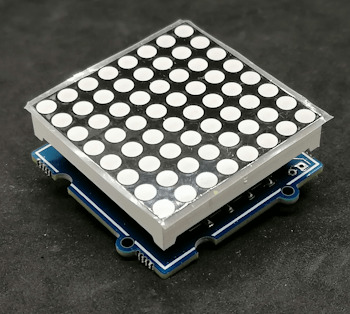
8x8 LED Matrix mit HT16K33 Treiberchip
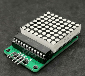
8x8 LED Matrix mit MAX7219 Treiberchip Jedoch kannst du diese Matrix zu mehreren zusammenstecken und so eine schier endlose Anzeige aufbauen.

MAX7219 Shields auf einem Stativ Die LED Matrix mit Grove Schnittstelle jedoch kannst du nicht so kaskadierend aufbauen und somit bist du mit dem Modul in deinen Möglichkeiten stärker beschränkt.
Fazit zur Programmierung der 8x8 LED Matrix mit Grove Schnittstelle am Arduino
Die LED Matrix von Seeedstudio mit Grove Schnittstelle und HT16K33 Treiberchip lässt sich super einfach programmieren. Du benötigst wenig Code und über die I2C Schnittstelle und dem Grovekabel hast du deutlich weniger Verkablung als bei der LED Matrix mit MAX7219, leider vermisse ich hier die Möglichkeit die Module kaskadierend zu verbinden und so ein langes Display für Laufschrift aufzubauen. Mit dem Online LED Matrix Editor kannst du dir jedoch recht einfach kleine Frames für die Matrix erstellen und in den Code kopieren. Ausblick Ich werde nun mal schauen, welche kleinen Projekte man mit dieser Matrix aufbauen kann. Jedoch würde ich eher zu einer RGB Matrix tendieren, denn diese kann bei gleicher Baugröße verschiedenfarbige Pixel anzeigen. Read the full article
0 notes