#Logic Circuit
Explore tagged Tumblr posts
Visit Tumblr Blog
Explore Tumblr blogs with no restrictions, modern design and the best experience.
Last Seen Tumblr Blogs


Fun Fact
China blocked Tumblr because of pornography and censorship problems in 2013.
Text
Corporations sold the idea that artificial intelligence would remove the need to work to the general public. This will never be true. Currently, artificial intelligence is only being used by a small amount of people to do better work. Everyone else is being trained by the AI and not the other way around. In the end AI will only be used to verify if something is true or false. A basic LLM running on a quantum logic circuit.
1 note
·
View note
Text
https://www.futureelectronics.com/p/semiconductors--logic--74-series--a-hc-t/74hc594d-118-nexperia-1604081
74 A/HC/T Series Applications, programmable logic gate, digital gates
74HC Series 6 V 8-Bit Shift Register with Output Register - SOIC-16
#Logic#74 Series#A/HC/T#74HC594D#118#Nexperia#chip manufacturers#FCT#A/LVT#logic gate circuit#logic gate#chips#Logic Circuit#digital gates#gate logic#electronic logic gate ICs#programmable logic gate
1 note
·
View note
Text
Bus-hold devices, 74HC family High-speed CMOS circuitry, Logic Circuit
74HC Series 6 V 3-State Surface Mount Shift Register - SOIC-16
#Logic#74 Series#A/HC/T#74HC595D#118#Nexperia#Bus-hold devices#74HC family High-speed CMOS circuitry#Logic Circuit#what is a 74-series chip#7400-series integrated circuits#LED lighting#74HC TTL#logic integrated circuits#7400 logic gates
1 note
·
View note
Text
Logic Circuit, Types of 74 A/HC/T Series Logic Chips
74HC Series 6 V 3-State Surface Mount Shift Register - SOIC-16
#Nexperia#74HC595D#118#Logic#74 Series#A/HC/T#Logic Circuit#Types of 74 A/HC/T Series Logic Chips#Electronic parts#what is a 74-series chip#LED lighting#LED lights#74 series chip manufacturers#LED parts#LED light accessories
0 notes
Text
74 A/HC/T Series Logic Chips, Types of 74 A/HC/T Series Logic Chips
74HC Series 6 V Dual Retriggerable Monostable Multivibrator with Reset - TSSOP16
#118#Nexperia#74HC123PW#Logic#74 Series A/HC/T#Series Logic Chips#Types of 74 A/HC/T Series Logic Chips#74HC High-speed CMOS circuitry#Three-state output#combining the speed of TTL#TC74HC/HCT Series#Logic Circuit#NAND Gate
1 note
·
View note
Text

a triangle and a logic gate enter a bar
((context under the cut if u dont get it))

this is an inverter (circuit/breadboard thing)
if you input something it'll output the opposite
in other words, input "A" and itll output "NOT A"
usually used for conditions like "f B and not A then C"
this is a sign that engineering is taking over my life
send help
#gravity falls#bill cypher#breadboard#circuits#logic gates#engineering#electrical engineering#yaoi dorito#this has so many errors but i did it instead of hw so idc#my art#my comic#art#annnnnd post!
24 notes
·
View notes
Text


Reila Audrey Haas / Logic
x x x x x x x x x Banner
#circuit#f&h#f&h2#f&h termina#fear and hunger#fear and hunger 2#fear and hunger termina#fnh#logic#olivia haas#reila haas#robot#spoilers#stim#technology#the machine god#content: stimboard#cw: flashing
81 notes
·
View notes
Text


Oct 29, 2023 • Sunday
GUESS WHO'S BACK
Exams are just around the corner, and I have recovered (mostly) so got back to productivity. I missed my notes <3
The 1989tv vault tracks are stuck in my headddddd my favourite is Now that we don't talk. If you are a swiftie, what is your favourite vault track?

Things I did today:
40 out of 55 slides of a PPT
19 out of 27 concepts from Module 1 of computer science
Ate biryani :3 (and then had a tummy ache LOL)
P.S. the whiteboard is @studaxy's I STOLE IT (jk, they gave it to me lol)
🎧 Suburban Legends — Taylor Swift
#dailyfoxposts#foxcomp#studyblr#codeblr#studyspo#study#coding#note taking#physics studyblr#math studyblr#compblr#computer science#boolean algebra#logic gates#digital circuits#exam#exams#study motivation
120 notes
·
View notes
Text
Using woodlouse logic gates in your natural circuits.
Isopods have 7 pairs of legs all pretty much the same length.
74** logic gates have … 7 pairs of legs all the same length!
Coincidence? I think not!
Clearly, each isopod contains 4 logic gates. This Armadillidium vulgare has 4 AND gates. Don't forget to connect power & ground legs & use pull-down resistors on inputs.
(best practice is to simply ask the rollie to position itself in your circuit.)
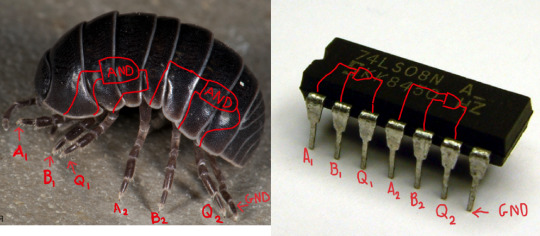
Like most natural systems. they use micro-voltages, don't use standard 5V power sources.
#circuits#logic gates#7408#AND gate#isopod#woodlouse#rolly polly#sowbug#natural circuits#engineering#circuits jokes#breadboard
132 notes
·
View notes
Text
GUYSSSSSSSSSSSS Its sojoever
7 notes
·
View notes
Text
Imagine judging mdzs using Christianity be like...🙄🙄🙄 even Buddhism could not be used to judge mdzs as literature. Why? Simply because XianXia literature isn't about religion! Religion is revolving around a God, whereas XianXia's concept is about "becoming a God themselves". The immortality concept in XianXia isn't about living forever to wait for true love like a certain vampire, however, it's about advancing to another higher realm and becoming Gods or Immortals.
The Lan Clan descended from a monk, but does any of the Lan Clan behave like a devoted monk? Of course not. Because they no longer are a monk. They're Daoist. Even Song Lan who came from a Temple, did he behave like a legit monk? Naturally not, because the Temple in mdzs has also been integrated with Daoism. The Buddhism in MDZS or XianXia literature is not the orthodox Buddhism as religion. It is a WAY, a PATH, to attain the Dao, in Daoism culture.
So, even using the related religion, Buddhism, couldn't be used to judge mdzs without considering its Daoism concept, not to mention using Christianity, a concept extremely out of context with the literature to begin with????
How to judge mdzs? Isn't it obvious?? Of course you have to use the Foundation of mdzs itself, a XianXia literature, with Daoism Concept, you dimwit!
#Why do people have weird brain logic#I cant anymore#Why are there more and more fans with stunted brain circuit in the fandom#The answer is painfully obvious but you have to make a fake analysis on your own right??#mdzs#mo dao zu shi
52 notes
·
View notes
Note
Crying weeping sobbing NO don't do that to him he's my baby
What if Y/N got reborn. What then. Maybe as an omnic this time, or they stay human, either way they remember and they gotta kiss Ramatta
OR they don't remember, but Ramattra just knows it's them, their eyes, their demeanor,
"This isn't the first time we've met, is it?"
"No, my love"
"I'm glad you found me again"
"I never stopped looking for you, and even after the end, when the sky is burning, and this planet is no more, if you perish with it, I'll look for you."
"Will you find me?"
"Always"
"I'll meet you half way there"
"I'll be waiting"
This is so tangentially related but bear with me ok. What the fuck do we call Orisa and Echo? They aren't technically omnics (i.e. not built by Omnica corp nor gained sentience via the Awakening-- hell, the most recent Echo novel had Liao not entirely sure that Echo was sentient yet, right?)
But! Being reborn as some kind of synthetic life has so many interesting implications. Why did your soul get stuck in this body? Was it just luck that you get to go around again in a form more familiar to him or was there a reason? (and likewise, who made your body & for what purpose?)
I love that he would just... believe you. Just seeing someone and knowing it's you, not understanding how or why...
#you being reborn as a human is fucking hilarious tho like a lil 5 y/o kid going up to him#you've been dead five years his grief has consumed him entirely he's bitter and angry and so very alone and#this lil fucking human kid marches right up to him- completely unafraid- and is like hello???#wtf do you think you're doing??? yeah I was real fucking cross with you call your fucking cruiser down we're gonna have a talk#Ramattra genuinely would think he's lost his goddamn mind like. he's completely blown a logic circuit#kat answers
11 notes
·
View notes
Text
Logic Circuit, Types of 74 A/HC/T Series Logic Chips
74HC Series 6 V 3-State Surface Mount Shift Register - SOIC-16
#Nexperia#74HC595D#118#Logic#74 Series#A/HC/T#Logic Circuit#Types of 74 A/HC/T Series Logic Chips#Electronic parts#what is a 74-series chip#LED lighting#LED lights#74 series chip manufacturers#LED parts#LED light accessories
1 note
·
View note
Text
How a Computer Works- Part 4 (Binary Math)
This is the 4th part in a series of posts explaining how computers work such that you can build your own from just wires and spare electronics (or hell, Minecraft redstone signals, a carefully balanced water fountain, anything you can build logic from really). The series starts in this post, the most recent entry before this was part 3, but the only REALLY required reading for this one should be part 2. Get that knowledge in your brain so this next bit can make sense to you.
Also, I'm basically teaching a pretty in-depth computer science class here for free out of the goodness of my heart, so if you have the cash to spare, maybe consider throwing a little money my way so I can keep surviving and doing stuff like this?
Our focus for today's lesson is going to be actually designing one of these modules we have hooked up to the bus to actually do stuff with any data we pass into it. As I've mentioned a few times, all of this stuff we're passing along can be thought of in a lot of different ways. Completing a circuit when one tracing wires out connects to a positive charge and another a negative means the same thing as a gate saying true, will turn a light tied in there on, we can call it a 1 in our abstract computery talk, or several other things, but we're dong math today so let's think about numbers.
Let's think in Binary
So I think I've referenced binary numbers a few times in a really hand-wavey sort of way, but it's good to stop and make sure we all get the concept thoroughly. Normally, when we think about numbers, we're using our good pals the Arabic numerals- 0 1 2 3 4 5 6 7 8 9. We just decided to make unique little squiggles to represent these first ten numbers if we include 0, and then if we add together 9+1, we're out of symbols, so we start a new column, put a 1 in it, and reset to 0 in the one we're in. So, 9+1=10. We call this "base ten math" because ten is where we have to start that new column... but really, we kinda just picked ten out of a hat for this? Presumably it's because most of us have ten fingers.
Maybe if we all had hands like typical American cartoon characters, we'd only have made eight unique symbols. 0 1 2 3 4 5 6 and 7. Add 1 to 7 and we start a new column there instead of after coming up with symbols for those fingers we don't have. In base eight math, 7+1=10. It's a smaller group we're dedicating that next numeral over to, but you can see how that works, right?
Or hey, what if the first person to start counting stuff on their fingers just thought about it differently. You can totally hold up 0 fingers. So really on just one hand you can easily go 0 1 2 3 4 5. Well, what if we just use our other hand past there? Every time we run out of fingers on our right hand, we reset it to zero and add one on our left. It's base six math in this example but hey with just our hands we can display any number from 0 to a base six 55! Which in base ten would be, let's see, 5x6+5, so, yeah, any number from 0 to 35, but that's still pretty good. Converting it into base six is kind of a pain since you've gotta stop and do the multiplication, but if we all just kinda thought in base six we wouldn't need to convert at all.
And hey, what if we really thought big here? Instead of using one hand for the next column of numbers, we could just treat every finger as a column on its own. Holding some of the required groupings of fingers up can kinda give you a hand cramp, but hey we've got ten columns that can hold a 0 or a 1, so we can count all the way up from 0 to 1111111111! Or uh, in base ten, 1023. Still a really impressive number though! Just explaining this to you I've upped how how you can count on your fingers by more than a hundred times. You're welcome! Sorry about the hand cramps. We're not looking into binary math for the sake of saving fingers though, we're doing it because we're designing logic circuits and doing math on the assumption that the only symbols we have to count with are 0 and 1. Anyway, just so we're on the same page, let's count up from 0 in binary for a while here:
0, 1, 10, 11, 100, 101, 110, 111, 1000, 1001, 1010, 1011, 1100, 1101, 1111, 10000.
You can follow along with the pattern right? And if you're curious what that'd be all standard base 10 style, let's count through that same number of... numbers that way.
0, 1, 2, 3, 4, 5, 6, 7 8, 9, 10, 11, 12, 13, 14, 15, 16. I made some of these bold to make it a little easier to count along. It's the ones where we're adding a new column in binary, and hey look, it's all the powers of 2. If you have to convert in your head, that makes it easier.
Binary Addition
So let's try thinking in JUST binary now and do some basic math. Before we get into the double-digits- Wait no, if we're pedantic, di- is the prefix for ten things so we shouldn't be saying "digits," we're in base two, so, bi- so... the double bits, I guess), we're just got:
0+0=0. 1+0=1. 0+1=1. 1+1=10
Hey, wait. does that pattern look familiar to you? Like we had to go to a second bit for 1+1, but just ignore that for a moment and look at the lowest one. Humor me. We saw this same pattern in part 2!
0 xor 0 outputs 0. 1 xor 0 outputs 1. 0 xor 1 outputs 1. 1 xor 1 outputs 0.
Oh damn. So if we want to add two bits of data, we just XOR them. All we have to worry about is the spill-over into the next column. Well.. hell, let's see what this looks like if we're looking at two columns here.
00+00=00. 01+00=01. 00+01=01. 01+01=10.
If we just look at the "1s column" digit, yeah, XOR works. And is there a pattern for the "10s column?" Well, it's a 0 for everything except when we go 1+1... we had a logic circuit for that too though, right? Yeah, good ol' AND. Only outputs 1 if both value A and value B it's looking at are both 1.
So OK. We rig up a circuit that has a XOR gate and an AND gate. We feed the first number we want to add into both of these gates, and we can display our answer as a two bit number, with what the AND spits out on the left, and the one the XOR spits out on the right. BAM. We are masters of addition... so long as the highest numbers we want to add together are 1+1. We uh... we should probably try to improve upon that. Also we've got this whole structure to the whole computer where we've got these registers feeding in and out of a bus with a fixed number of data bits on it, kinda would be nice if the number of bits going back out to our bus was the same as the number coming in to our addition circuit... and like, yeah, that's kind of an impossible goal since it's always possible when adding two numbers the same length that you need an extra column to display the answer, but you know, if the first bit of at least one of the numbers we're adding is a 0 it'll fit, so let's get to that point at least.
So OK. Let's expand things out. We're adding any 2 bit numbers now, and let's pretend we've got like a calculator with a 3 bit display.
000+000=000. 001+000=001. 000+001=001. 001+001=010.
010+000=010. 011+000=011. 010+001=011. 011+001=100.
000+010=010. 001+010=011. 000+011=011. 001+011=100.
010+010=100. 011+010=101. 010+011=101. 011+011=110.
I'm being kinda redundant with showing 0+1 and 1+0 and such. Let's narrow these down to just the ones we need a new bit of logic to make happen though. The 1s bit is groovy. We feed the 1s bits of ANY two numbers into a XOR gate, we get the correct 1s bit for our answer. And if the next bits over are 0s, we can pop what's coming out of our AND gate in there out to there and that's fine too. We're also good if we just look at the 10s column, everywhere we don't need to worry about the 1s column affecting it. The places where we need to do more with our logic are just where we're doing the whole "carry the 1 thing." I already set up the grid of all these so that's just the stuff in the far right column, but hey, let me bold those up too.
And let me just kinda blank out these other bits so we're really focused in on the part where there's a problem...
_0_+_0_=_1_. _1_+_0_=_0_. _0_+_1_=_0_. _1_+_1_=_1_.
Well huh. If we're just looking at a bit in the middle of our big long number, and we're carrying a 1 to that position, we sure seem to be getting the exact opposite of what we get when we aren't carrying anything in here. So OK, let's redesign our logic circuit here. We've got our bit A wire and our bit B wire coming in like we did before, going into that XOR for this output bit, but we need to add a wire for whether we're carrying a 1 in from the next circuit over, and if so, flip that result. Do we have a way to do that easily? Well OK, logic chart time. If we have a 0 and no carry, we want 0. I'm lazy, so, 0 bla 0=0, 1 bla 0=1, 0 bla 1= 1, 1 bla 1 = 0. Oh, that's another XOR gate. We XOR A and B like before, and then just XOR that result with our carry bit, and we are definitely displaying the right thing in this part of our answer. Now we just need to double check if our corner case of handling a carry messes with the next carry anywhere and... oh damn yeah.
011+001=100, and 001+011=100. These are the cases where the 1s column carrying a 1 to the 10s column means we have to do something different with that carry bit. So, we're still making our carry-the-1 result a 1 if A and B are 1... but we also need to make sure it's a 1 if we are both carrying something in, AND our original XOR gate is spitting a 1 out. Well we can throw that AND in there, and we can throw in an OR to check either of these two conditions, and there's our new and improved carry-the-1? result.
So let's put it all together now!
For a given bit, we have value A, value B, and Carry. We have a XOR gate that takes A and B in. We feed the result of that and Carry into another XOR gate. That spits out the sum for this bit. Then we AND the result of that first XOR and our Carry feed that result into one side of an OR gate. We feed A and B into a second AND gate, the result of that is the other input for our OR. That OR now spits out a fresh Carry bit. We can plug that into the next adder circuit down the line, for the next column to the left in our result. BAM, there we go. Just clone this whole weird set of 5 logic gates for as many bits as you want to deal with, daisy chain those carry values into each other, and congratulations. You have somehow rigged together something where electricity goes in, electricity goes out, and the weird path it has to take along the way has this weird side effect where you can work out what two binary numbers add up to. Please note again that we didn't at any point make some sort of magical computer person and teach it how to do math, we just found patterns in how electricity flows and where the pure math concept of logic gates and binary math happen to work the same way and exploited that for a result that's convenient to us. Shame that was such a pain wiring up, but hey, every time you add another copy of this onto the end, you double the range of numbers you're able to work with. Eventually that hits a point where it's worth the effort.
Well addition is all well and good, what about subtraction?
OK, so just to take stock, so far we have a big addressed block of memory somewhere we keep our numbers in. We have, for example, 8 bit lines on our bus, and when we want to do addition, we set stuff that turns on "hey, place with our first number, put it on the bus" then "hey register A, read the bus for a moment," then the same to get a number to slap in register B, and we've got this sum register sitting between registers A and B with a bunch of these adder circuits hooked in between all the bits. We might have some leftover carry line with a 1 on it and nowhere to plug it in, but ignoring that spill-over, every bit on our bus is to go good for addition. When we're setting up command codes, we can make more to do some other math with A and B and that's all well and good, but we have a real big problem when it comes to subtraction, because out of what's going into A, going into B, and coming out of sum, at least somewhere we're going to need to deal with the concept of negative numbers. So when we're doing subtraction, one line on our bus needs to be reserved for whether it's positive or negative. If you program, you're maybe familiar with the concept of unsigned integers vs. signed integers? This is that. With only positive numbers, if we've got say, 8 bits to work with, we've got a range of 00000000 to 11111111 to work with, or 0-255 in decimal, but if one of those is getting swiped for negative or positive, now we're talking like, -127-127.
But wait, that's not quite right, is it? Like if we arbitrarily say that leftmost digit is 1 if we're negative, we get things like, 1 being 00000001, 0 being 00000000, -2 being 10000010 etc. but... what's 10000000? -0? That's the same thing is 0. That's redundant and also gonna really screw the count up if we're like, adding 5 to -2! Or really, any other math we're doing.
Oh and we also need to remember when we're stuffing a negative number into a memory register, it's not like that register knows what concept the bits we're shoving into it represent, so like, you personally have to be responsible for remembering that that 1 on the leftmost line, for that particular value, is noting that it's negative, and not that the 10000000s place or whatever has a 1 for some number, or the first of 8 switch variables you're stashing in this address to save on space is on, or whatever else. We here at the memory address hotel are just trapping electron wiggles in a weird little latch or we aren't. No labels, no judgements.
So OK no matter how we're storing negative numbers we need to just actually remember or take notes some way on what the hell convention we're using to represent negative numbers, and where we're applying it. But we also need a convention where like, the math works, at all. Just having a bit be the is it negative bit works real bad because aside from having -0 in there, we're trying to count backwards from 0 and our math module has no conception of back. Or of counting for that matter. Or 0. It's just a circuit we made.
OK, so, let's maybe store our negative numbers in a different way. You know how a car has an odometer? Rolling numbers counting up how many miles you've gone? And there's a point where you run out of digits and it rolls back around to 0? Well funny thing about our addition thing is if you add a 1 to a display of all 1s, that also rolls back around to 0 (and has that carry value just hanging out in space unless we have a better idea of what to plug it into). So if we like, have all the numbers we can display printed out on paper, and we represent that rolling over by just rolling the paper up and taping it, so we have a bit where the count is going like: ..11111101, 11111110, 11111111, 00000000, 0000001... well we can just arbitrarily declare that all 0s is really 0, and the all 1s before it is -1, etc. Try to make that work maybe. And still remember that 10000000 or whatever is where we abruptly loop back between the highest positive/lowest negative numbers we're handling.
Here's a funny thing though. If we start counting backwards, we totally get this inverted version of what we get counting forwards. Just going to show this with 3 bits for convenience but going up from 000 you go:
000, 001, 010, 100, 101, 110... and going back from 111, you go
111, 110, 101, 100, 011, 010, 001... and yeah, look at that with a fixed with font, and it's all just flipped. And huh, you know what else is cool? If we go back to saying the first bit is 1 for negative numbers and a 0 for positive, you can just add these and it almost works. You want to subtract 1 from 1, that's the same as adding 1 and -1. Invert the negative, that's 001+110=111... 1 shy of the 000 we want. Huh.
What about 2-2? 010+101=111. 3-3? 011+100=111. Everything that should be 0 is 111, which is 1 less than 0 when we roll over. What about stuff that should be positive? 3-1? 011+110=(1)001. 2-1? 010+110=(1)000. 3-2? 011+101=000. Still all 1 off if we just ignore that carry going out of range.
-1-1? 110+110=(1)100, which translates back to -3... and that's kinda the only example I can give that's in range with this, but throw in more bits and follow this convention and it'll all keep working out that you get exactly 1 less than what you want, turns out. So, if we're in subtract mode, we just... invert something we're bringing in then add 1 to it and it should all work out?
So OK. We have a wire coming into math land from what mode are we in, it's a 1 if we're doing subtraction. We XOR that subtract line bit with every bit of what's coming into B, that does nothing if we're in addition mode, but if we're in subtraction mode, we're flipping every bit, and tada, the subtraction works without any other changes. We just need to conditionally add 1 if we're in subtract mode now but... wait, we already have literally that. We just take this same "we are in subtract mode" wire and run it in as a carry-in to the rightmost bit of our adder chain. Again, if we're doing addition, that just carries in a 0 and does nothing, but if we're in subtraction, it carries in a 1, and... we're done. The explanation was a long walk, but yeah, when subtracting, just add those extra XORs, plug in that carry, and remember your negative numbers are all weird in storage. Done.
Let's do multiplication and division next!
No. We can't do that.
Well seriously, that's not a thing we can just layer on top of this relatively simple thing we have wired up. We've got this lean mean math machine will give you whatever result you need basically the instant you load values into A and B. Definitely by the time you, being conscientious about not leaving the doors to the bus open all the time, officially flag things to write out from sum and into whatever destination. Multiplying and dividing though, we need more steps, and we need scratch spaces for temporary values. I suppose if you're careful you can multiply by like, loading 0 into B, load the first number you want to multiply into A, just feed sum directly into B, and pulse the clock however many times you want to multiply, but... you probably don't want to just constantly be reading and writing like that, it's tying the whole bus up, unless you have an alternate pathway just for this, and you have to keep count. Still, I'm assuming that's how people do it when they build a dedicated function in. I'm still looking at older systems which assume you're going to do most of your multiplication one step at a time, running through some code.
There's one big exception though. If you multiply any number by 10, you just add a 0 onto the end of the number... and guess what? I'm not using "10" specifically to mean "ten" here. Whatever base you're doing your math in, that still works. So in binary, if you just want to specifically multiply by 2, it is super easy to just shift every bit to the left. Like, have some sort of "shift left/multiply by 2" wire come in, set up logical conditions so that when its set, all we do is have the bit that we are feed into the carry flag, then for the sum ignore everything but the carry flag. 00011001 turns right into 00110010. I picked that out of a hat, but that's binary for 25 getting doubled to 50 as I eyeball it here. Dead simple to do as a single operation. Shifting everything to the right, AKA dividing by 2 is similarly simple... and hey, you might notice that in say... very old games, there's a whole lot of numbers doubling. Like ghosts in Pacman? Each is worth twice the points as the last? Yeah that's because that's easy to do fast.
Other math though takes more steps, and tends to involve extra hardware design to make it work. Like if you're doing division where you aren't guaranteed to have a whole number at the end, so, most division? Suddenly you need to have decimal points in all of this, and work out where they go, and this is why you hear people talk about "floating point processors" as this whole special thing that we just did not have for decades. For now at least, that's beyond the scope of what I'm teaching. Might get there eventually.
A final bit about bits...
So hey, we need to pick some arbitrary bit count for how wide we make our bus and our registers, and also some number for memory registers, command codes, maybe other stuff. And you just kinda want to pick a nice round number. You can't pick ten though, because ten isn't a round number in binary. It's 1010. So usually, we round down to 8, nice and simple, or we round up to 16. And then if we're like filling out charts of values, it's easier to count in those bases. Counting in base 8 is easy enough. 0 1 2 3 4 5 6 7 10. With base 16 though, we need 6 more symbols in there, so we go with 0 1 2 3 4 5 6 7 8 9 A B C D E F 10. And sometimes people make a point of making the B and D lowercase, because if you want to display those on the sort of 7-segment display you still see on cheap clocks or things going for an 80s look, B and 8 are too similar, and D and 0. Base 16 is also called hexidecimal. People will shorten that to "hex" and you see it a ton when people are looking at raw data and don't want to get thrown by long binary numbers, and it particularly gets out to the general public when we're talking about like, 8-bit color values. 8 bits gives you a number from 0-63, hey that's just 2 digits in base 16, so like, for HTML color codes, you can use 2 digits each for red green and blue values, and technical artists just kinda memorize stuff like "right so FFFFFF is white, 700080 is a pretty bright, slightly blue-ish purple, etc."
We tend to go with 8 bits in most places though, or some multiple of 8 anyway, and someone randomly decided to call 8 bits a byte, and that's kind of just our standardized unit for measuring data now. Well mostly standardize. Because people will say, like, 1 kilobyte is 1000 bytes, but in practice people actually round things off to binary values and they're going to actually be off a little.
Anyway, linguistic trivia! Whatever number of bits it is we store in a register/load to the bus is called a "word" and we talk about how many bits long our words are, because once you design the architecture, you're stuck with it and all. And sometimes you want to be space efficient and not use a whole word, so you do some logic gate trickier to chop off whatever portion you don't need when reading it and not change what parts you aren't trying to when writing it and just kinda store multiple variables in a single value. One common thing that happens as a result of this is that you'll break up an 8-bit value because you just want like two values from 0-15 instead of one from 0-255. And when we're working with one of those half-bytes, because puns, the actually term for that is "a nibble." No really. And if we're using a single bit for a variable a lot of the time we call that a flag. Common to see a byte used to hold 8 flags.
For now let me just point anyone following along with this at this first post of me talking about the game console I'm designing. That's a pretty similar topic to this one.
Let me also point you again at my patreon, too.
CONTINUED IN PART 5
20 notes
·
View notes
Text

#musical theatre#musicals#legally blonde the musical#legally blonde#emmett forrest#amatuer musical theatre#amatuer theatre#this gets even more fun when you're friends with the guy too#like my brain knows it makes no logical sense#like any of it#at all#but i think my love for the character of emmett must just shine through no matter what#beths rambling in the tags again#im currently in rehearsals for this show again after doing it at uni#and my brain short circuited while I was watching a scene yesterday all because our emmett crossed his arms and his forearms looked toned#ive known this guy for like a year and a half#but now i can't even make eye contact with him or watch him on stage#what is my brain?
3 notes
·
View notes
Text
i'm not saying that albon will crash again- but if he does, does any new parts count against his allocation or since he is driving logan's car will it count against logan?
#haven't seen this asked yet#maybe it is common knowledge and it's just me who doesn't know#i'm very upset about their decision#logically sure alex is more likely to score points#but he's also crashed twice in 2 years at the circuit now#and it is just so unfair that logan is punished for alex fucking his car#f1#australia gp 2024#logan sargeant#alex albon
18 notes
·
View notes