#automotive tube components
Explore tagged Tumblr posts
Visit Tumblr Blog
Explore Tumblr blogs with no restrictions, modern design and the best experience.
Last Seen Tumblr Blogs


Fun Fact
Premium Tumblr themes are available from anywhere between $9 to $49.
Text

Die cast parts
Sebros manufactures High Pressure Die cast machined parts, Tubular components and Fabrication assemblies. We supply to major OEMs in India, USA, Canada, Mexico and Europe. The industries we serve are Automotive, Power, Oil & Gas, Chemical, Construction and Industrial hardware.
#Die cast parts#automotive tube components#hydroformed stainless steel bellows#die cast engine gearbox parts#door frames#bend pipes#radiator pipes
0 notes
Text

So — what are metal fabrication services?
In today's rapidly growing industrial world, metal fabrication services have been very helpful and useful in shaping a number of products for different industries including automotive, construction, aerospace and manufacturing. ABOUT MANUFACTURING At the forefront of delivering high quality, precision-engineered metal components that meet exacting standards in mass production. APPLICATION Get restorative help for your tired looking auto parts now!
Metal Fabrication Services: What is it?
Metal fabrication is an extensive process that consists of cutting, bending, welding and assembling metal materials to produce certain items or parts. Metal fabrication is so wide-ranging gig that includes a bunch of elemental processes including;
Cutting: It is an accurate process of taking away the material from a metal sheet or tube by using methods such as laser cutting, water jet cutting and plasma cutting. The method chosen will depend on the material type and desired precision.
Bending:- This step works on the principle of applying force to metal in such a way that mold it into the desired shape. Press brakes (20% Up) or similar machinery are the tools bending all your components that must be done accurately and identical to one another.
Welding : Welding is the process of joining two or more metal parts by melting the contacting faces and allowing them to cool in order to join them. The metals being formed together will determine the process and type of weld to be used (MIG, TIG or spot welding).
Assembling: In this last phase, parts created are assembled into the final product. This may involve extra steps such as painting, coating or any other finishing methods that help to protect metal and give a much better look.
Why to Opt for Metalman Auto Ltd. For Fabrication Services?
At Metalman Auto Ltd., we are what can be called your one stop, when it comes to anything metal fabricated. Why we are different from rest of the companies in this industry:-
Capabilities: In our cutting-edge facilities, we handle a variety of fabrication processes from sheet metal fabrication to tubular fabrications that allow us to meet any related requirement.
High Precision and Quality: We manufacture high precision components with in-house machines backed by the latest technology strictly observing quality norms. We take pride in our work and every product which we manufacture is of the highest quality, robust, reliable as per clients specification.
Well-Experienced Workforce: We have our team of skilled engineers and experienced technicians who instill the creativity to solve all these methods, ensuring perfection in each project. This means investing heavily in training and development to ensure our workforce is at the very forefront of industry technology.
Tailored solutions: We know that every project is different and as a result, we take the time to work with clients on tailored solutions based around their needs and objectives. Metalman Auto Ltd., we can fulfill your need, no matter how large scale or custom requirements you might have.
Sustainable practices: We are committed to sustainability, using sustainable eco-friendly materials and processes whenever possible. Our focus on improving efficiency leads to cost savings, and waste reduction creating a better tomorrow for all of us.
Key Services We Offer
Offering a range of services to meet the requirements of industries, Metalman Auto Ltd. is acknowledged in providing metal fabrication works across different industrial sectors:
We have predominantly been into manufacturing of automotive components In the segments two-wheelers, three-wheelers passenger vehicles, commercial vehicle and off-highway since 2008. Our experience in this domain allows us to deliver Long lasting and good quality which help vehicles for better performance.
Industrial and Agricultural Machinery: We offer high quality stringent metal fabrication services to the agricultural industry producing durable, functional components with long life durability for a variety of machinery.
White Goods & Aesthetical Components: We also specialize in manufacturing aesthetic white good components like : washing machine front panel, rear panels etc.
Metalman Auto Ltd. strengths
Excellence through Experience: We come from a background of over 30 years in the metal fabrication business and our legacy as an industry leader speaks for itself. Proud of our heritage, we just say that Trading Depot is the rimstead for quality and customer service.
Innovation & Technology: It is important for us as an organization to keep utilizing the latest technology and machinery in our industry. Using our new innovative methodology we can help provide advanced components solutions to the ever changing needs of clients.
Location-Out efficient facilities have been laid out at strategic locations across the region to enable quick delivery for our clients.
It is just the beginning of a long lasting bonding with our clients; we believe in building strong client relationships and at Metalman Auto Ltd. We are a customer-focused company and we always put our customers before us, in providing them solutions beyond their imagination.
Conclusion
Metal fabrication is the process in which raw metals are turned into a variety of products. It can transform completely pipes, metal bars, steel sections & sheets to finished shop products using different processes like forming machining welding, cutting drilling and so on [1]. We at Metalman Auto Ltd., understand the varying demands of our customers and offer top-quality metal fabrication services to address them. If you need industry standard components or custom solutions our team is available to assist in the realization of your objectives as quickly and cleanly as possible.
Contact us today to inquire about our services or project needs.
#Tube fabrication for automotive applications#Precision tube bending services#Tubular components manufacturer for OEMs#Automotive tubular parts fabrication#Custom tube fabrication for vehicles#Metal tube fabrication for automotive industry#Precision pipe fabrication services#Tubular assembly solutions for automotive OEMs#automotive industry#car accessories#manufacturer#electric vehicles#metal fabrication#automotive parts#fabricationservices#metalman auto#automotive#oem manufacturing
1 note
·
View note
Text
Steamboy Legoes
I think it just so happened Steamboy came in to my life right when Bionicles started to get bad, so around that time I made a lot of M.O.C.¹s based on the various machines from the film.
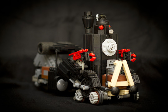
Since most of my legoes at that point were, in fact, Bionicles, I didn't have all that many parts to work with, so many of my builds were quite unorthodox. There's not going to be much S.N.O.T.², short for Studs Not On Top³, here. Also legoes aren't some holy relic that must be treasured above all else, so I cut, glued, and stuck paper on things as I saw fit⁴.
I also wasn't very good at taking photos that were in focus, so you've been warned.
Steam Automotive
This, being the first big crazy machine you see in the movie, it leaves a big impression. Its scene and music are also amazing so that helps.

I made this thing so many times. The gearing on the front wheels was always such a big thing for me, the fact that for it to move forward the larger gear had to rotate backwards was really eye opening for me at the time.

I was really quite inspired by seeing someone else's build of it, it was motorised and ran on tracks and had the monowheel on a rod in front of it. It was really cool, so much so that I'll forgive the fact that when the Steam Automotive was on the tracks it was in front of the mono wheel. I can't find it anymore, I swear there was more Steamboy stuff on Brickshelf at one point.

The way the machine has two drivers, a guy in the back in a more standard locomotive cab and then this guy in a tiny chair in front of the weird vertical second boiler/smoke box(?) with a head on it, its so interesting.


Honestly over this period the legoes I had was pretty consistent, but as I studied the reference materials I had closer and got a more complete idea of how everything went together my approaches changed a lot.
This was the last version I made, and probably the last M.O.C.¹ I made in general. It has a really different structure to the others, but some things have been retained. Sliding tires over 2x2 bricks and technic bushings to make tubes is a pretty good technique I think. Probably heretical in the church of lego purity though.

This model was kept together over my dark ages⁵, if you can call the period of time between when the legoes go in the attic to when they go on ebay that. I did think about keeping it, but there were too many parts from bigger sets in there, and I needed money to buy Rahi.
Note how by this point I'd just completely given up on miniature figures. They're just...so ugly lol, catering builds to fit those blocky awkward giants in was just not fun.
Most of the other builds are all one-offs after this point.
Steam Castle

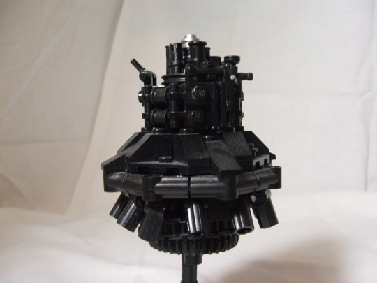
Except this one. I tried a couple times to give it more texture, but it was hard at the scale. Not really notable at all. Basically only made it because I had enough black connectors to make a circle.
Return of the Steam Automotive
It happened again.


This was basically made right after I watched the movie from memory, so that's why all the colours are off. The gears still work!

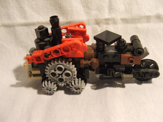
And I took a second crack at it. its such a pleasing design.
Aero Corps.


Structure wise this one is really accurate lol, but trying to fit it with a miniature figure just doesn't' work. I was really happy with the custom wings.
Aqua Corps.


I was really happy with the arms. I bet its illegal, but who cares lol, it works. Never even tried to fit a man in this.
Blimp
This was the biggest thing I made, and thus suffered the most from my lack of parts. It should be noted that the bulk of this stuff was built at once, even though I never took a group shot.
I had one wright flyer set and that's where all the tan panels for the tiny fraction of the air sack came from, the curve was just some click hinges but the panels were so heavy they had to be held held up with strings.


The biggest problem was always things with multiple identical components. It was a stretch to make the 6 fingers of this crab thing even with such a simple construction.
Legged Tank and Steam Trooper

I love this tank that appears in like 3 shots and in 1 is getting blown up and in another is dead. Why didn't I use a minifig for the steam trooper? I hear you ask, well, the backpack was more important for me, and I couldn't have a breast plate and a backpack without a major headache.
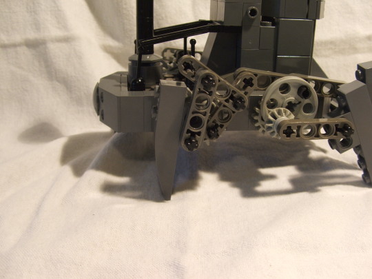
The linkages don't really do anything productive, except make it hard to rebuild the boxor in 12 years. But they looked cool.
This one really benefitted from me getting the collector's edition of the movie that came with a booklet that featured some concept art and renders. You barely see this thing in the movie, and certainly not from the back.
Flying Machine

I call this one the "I saw someone make this on brickset using revolvers and it looked really good, but all I have are brown muskets because my lego collection is a couple pirate sets from before I was born, bionicles, and the wright flyer".
British Tank
This was the second version, the earlier one was too bad even for me.

I didn't have the stuff to make custom treads so instead I just used the giant chain from the wright flyer and faked the thickness lol. I think that's a pretty good Union Jack for being done freehand on a tiny flat tile with some not very fine tipped sharpies.

Yes the boiler was held together with rubber bands why wouldn't it be.

Say hello to Mr. "Everyone in this movie has a moustache because its 1866 but I only have one miniature figure head with a moustache".
I was quite taken with how the gun was a separate unit that could be detached.
Monocycle

Ray's a part of it, it can't stay together without him. Its all just wedged in there. I got some very used lego once that had some parts of an old police station from the 80s in it, and some of the pieces weren't even broken! So I managed to salvage the back half of a bike from there.
I also made Edward.

Since I didn't have any brown sharpies I just stuck on some paper coloured brown with a marker. At some point I found that the glue I was using to stick the papers on also could rub the prints off so that was cool, saved sanding. Very few miniature figures from my childhood remained.
And this concludes a short look at my dark past. If for some reason you want to see more, there's some more photos of the older ones can be found on this brickshelf.
youtube
I wrote a big post about Steamboy over here, if this didn't scare you away.
Notes ¹Short for "My Own Creation". ²Short for "Studs Not On Top"³. ³Often abbreviated as S.N.O.T.². ⁴If the sight of such things disturbs you please leave the post now. ⁵Fans of legoes liken the part of their life when they aren't buying legoes to a period of scientific and cultural stagnation.
7 notes
·
View notes
Photo

New Post has been published on https://www.vividracing.com/blog/top-8-best-mods-for-a-800-hp-c7-z06-corvette/
Top 8 Best Mods for a 800+ HP C7 Z06 Corvette
If you’re looking to take your Corvette’s power and presence to the next level, you’ve come to the right place. In this guide, we’ll explore the top 8 best mods that can transform your Z06 into an 800+ horsepower beast, unleashing its full potential on the track or the street.
From enhancing exhaust notes to optimizing engine performance and improving traction, each of these mods plays a crucial role in elevating your driving experience. Whether you’re a seasoned enthusiast or just diving into the world of automotive upgrades, these carefully selected parts and accessories are sure to make a significant impact on your Corvette’s performance and aesthetics.
So buckle up, rev your engines, and let’s dive into the details of the Kooks Headers, Kooks X-Pipe, Borla ATAK Axleback exhaust, Cordes Performance upgrades including the 2.30″ LT4 Upper Pulley Kit and Engine Bay Ice Tank, the Low Side Fuel System for optimal fuel delivery, the traction-boosting Mickey Thompson Et Street SS Tires, and the stylish yet functional Forgestar D5 Drag Wheels. Get ready to experience the thrill of pushing your C7 Z06 Corvette to new heights!
youtube
https://www.vividracing.com/blog/wp-content/uploads/img-c7z06_forgestard5_mickeythompsonetstreet-3-scaled.jpg
1.) Kooks 1-7/8″ x 2″ x 3″ Stainless Steel Headers Chevrolet Corvette C7 2014-2019
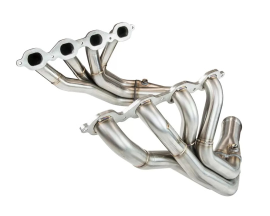
When it comes to elevating your Corvette’s performance, few names carry as much weight as Kooks Headers and Exhaust. With a legacy spanning over 50 years, Kooks has solidified its position as a leader in the High Performance Exhaust Industry since 1962. What sets Kooks apart is not just their reputation but their unwavering commitment to delivering top-notch headers and exhaust systems for street, race, and off-road applications.
The accolades speak for themselves – Kooks has secured hundreds of championships and set numerous records across renowned racing organizations like NHRA, IHRA, NMCA, NMRA, NASCAR, NASA, SCCA, and many others. This level of success is a testament to the quality and performance of Kooks products.
What makes Kooks truly special is their dedication to craftsmanship and American manufacturing. With three generations of family leadership at the helm, every Kooks product is handcrafted right here in the USA. This commitment to quality control and precision ensures that every header and exhaust system that bears the Kooks name meets the highest standards of excellence.
The Kooks Headers and Exhaust kit for the C7 Corvette includes a 1-7/8″ x 2″ x 3″ Stainless Steel Long Tube Header, Cometic Multi-Layer Gaskets, Stage 8 Header Bolts, O2 Extensions, and Torca Clamps. Crafted from premium 304 Stainless Steel, these components not only offer exceptional durability but also add a touch of aesthetic appeal with their stainless steel finish.
Fitment is seamless for various Corvette models, including the Chevrolet Corvette C7 LT1 6.2L (2014-2019), Chevrolet Corvette C7 Z06/Z07 LT4 6.2L (2015-2019), and Chevrolet Corvette C7 ZR1 LT5 6.2L (2019).
So, if you’re ready to “Get Kookin with KOOKS!” and experience a performance boost like never before, the Kooks Headers and Exhaust system is a must-have addition to your C7 Corvette.

2.) Kooks OEM X 3 X 2 3/4 (OEM) C7 X Pipe Chevrolet Corvette C7 6.2L -All models 2014-2019
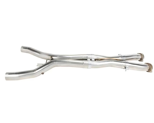
Upgrade your Chevrolet Corvette C7’s exhaust system with the high-performance Kooks X-Pipe. Crafted from T-304 Aircraft Quality Steel, this 3″ x 3″ X-Pipe optimizes exhaust gas flow for maximum power and a thrilling exhaust note.
Features:
OEM x 3″ Front connections to factory catalytic converter
3″ x 3″ X-Pipe
3″ x 2 3/4″ Mid-Pipes. Connects to 2 3/4″ OEM Style Exhaust.
Benefits:
Enhanced engine efficiency with reduced back pressure
Dyno and race-tested for optimal performance
Direct fitment for Chevrolet Corvette C7 6.2L models 2014-2019
Limited lifetime warranty to the original purchaser
Note: Designed for off-road use only and not CARB compliant for California.
Experience over fifty years of exhaust system craftsmanship with the Kooks X-Pipe, delivering power and performance for your Corvette C7.
3.) Borla ATAK Axleback Exhaust System Chevrolet 6.2L V8

The Borla ATAK Axleback exhaust system is the ideal companion to your Kooks X-Pipe and Headers upgrade for the Chevrolet Corvette C7, offering a seamless integration that results in a host of performance benefits. Together, these high-performance exhaust components optimize exhaust flow, reduce back pressure, and improve engine efficiency, translating into a noticeable increase in horsepower and torque for exhilarating acceleration. What truly sets this combination apart is the distinctive Borla Sound of Power, delivering an aggressive yet refined exhaust note that not only enhances driving excitement but also sets your Corvette apart from the crowd. Crafted from polished T-304 stainless steel, the Borla exhaust system not only ensures premium quality and durability but also adds a touch of visual appeal to your Corvette’s rear end. With precision CNC manufacturing and Borla’s Million-Mile Warranty backing, you can trust that your exhaust system will fit perfectly and be covered for the long haul. Together, the Kooks X-Pipe and Headers with the Borla ATAK Axleback exhaust unleash the full potential of your Corvette C7, offering an unmatched driving experience that’s as thrilling as it is refined.
4.) Cordes Performance 2.30″ LT4 Upper Pulley Kit Chevrolet Corvette 2014-2021

Upgrade your Chevrolet Corvette’s performance with the Cordes Performance 2.30″ LT4 Upper Pulley Kit, designed specifically for models from 2014 to 2021. This kit offers a significant improvement by reducing the pulley size from the OEM 2.5 inches to a 2.3-inch diameter, resulting in a boost of 2-3 psi over stock levels. Included in the kit are essential components such as a press-on hub, 10 titanium torx bolts for secure installation, and the pulley itself featuring the newest griptec finish for enhanced traction and durability. Notably, the OEM belt can be reused if you have a stock-size lower, ensuring compatibility and ease of installation. This kit is compatible with all LT4 superchargers, making it a versatile and effective upgrade for unlocking additional power and performance from your Corvette’s engine. Experience improved boost levels and overall driving excitement with the Cordes Performance 2.30″ LT4 Upper Pulley Kit, tailored to elevate your Corvette’s performance to new heights.
5.) Cordes Performance Engine Bay Ice Tank Chevrolet Corvette 2014-2021


Elevate your Chevrolet Corvette’s cooling capabilities with the Cordes Performance Engine Bay Ice Tank designed for models from 2014 to 2021. Cordes Performance Racing, renowned as the premier GM LTX/LTX motorsports company in Arizona, brings a wealth of expertise and passion to every product they offer. As a family-run business deeply committed to performance excellence, Cordes Performance Racing not only focuses on building high-level performing vehicles but also prioritizes the overall presentation, ensuring that you’re proud to showcase your Corvette. The Engine Bay Ice Tank is no exception, crafted using the highest-quality components to deliver optimal cooling efficiency and performance reliability. By maintaining lower engine temperatures, especially during high-performance driving or track sessions, this ice tank ensures that your Corvette operates at the peak of its performance, providing consistent power delivery and reliability. Trust Cordes Performance Racing to go above and beyond in enhancing your Corvette’s cooling system, enabling you to push the limits with confidence and enjoy an exhilarating driving experience every time you hit the road or track.
6.) Cordes Performance Low Side Fuel System Chevrolet Corvette 2014-2021

(Image may differ from actual product)
Enhance the fuel delivery and performance of your Chevrolet Corvette from 2014 to 2021 with the Cordes Performance Low Side Fuel System. Cordes Performance Racing stands as the premier GM LTX/LTX motorsports company in Arizona, driven by a deep passion for excellence in automotive performance. As a family-run business, Cordes Performance Racing not only focuses on building high-level performing vehicles but also emphasizes an overall presentation that you’ll be proud to showcase. The Low Side Fuel System exemplifies this commitment, utilizing only the highest-quality components to ensure optimal fuel delivery and engine performance. Compatible with Chevrolet Corvette C7 models from 2014 to 2021, including the C7ZO6 and C7ZR1 variants, this fuel system upgrade is designed to keep your vehicle at the peak of its performance, providing consistent fuel delivery and power output. Trust Cordes Performance Racing to go the extra mile in upgrading your Corvette’s fuel system, delivering reliability and performance that you can count on for every drive.
7.) Forgestar D5 Drag Wheel 18×12 5×120.65 50mm Gloss Black w/ Machined Lip

The Forgestar D5 Drag Wheel in 18×12 size with a 5×120.65 bolt pattern and 50mm offset is a game-changer for high-performance builds like the 800hp C7 Z06 Corvette. Forgestar performance wheels are renowned for bridging the gap between forged and cast wheels, delivering exceptional strength and lightweight characteristics crucial for demanding applications. Using an innovative rotary formed production process, Forgestar creates a lightweight cast wheel with strength and impact values comparable to forged wheels, making them ideal for street, racing, and drag racing applications. The Drag Wheel variant is drag strip approved with SFI 15.1 and 15.2 ratings, ensuring top-notch safety and performance standards. The wheel features a rotary forged flow-formed barrel, monoblock construction, and a Gloss Black finish with a machined lip, combining aesthetics with functionality. Its lightweight design not only enhances acceleration and handling but also clears big brake kits for improved stopping power. The raised center cap adds axle clearance convenience, while bead knurling ensures secure tire fitment. With a load rating of 1600 lbs and meticulous attention to detail in construction, the Forgestar D5 Drag Wheel is a must-have for high-performance enthusiasts looking to maximize their C7 Z06 Corvette’s potential on the drag strip and beyond.
Mickey Thompson ET Street S/S Tire – P345/35R18
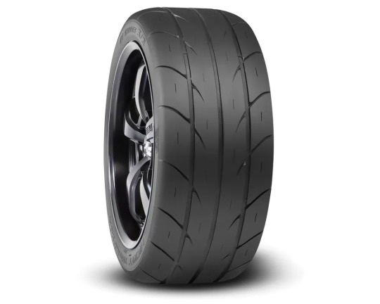
The Mickey Thompson ET Street S/S Tire in P345/35R18 size is a high-performance street-to-strip tire designed for enthusiasts seeking exceptional traction on both the street and the drag strip. Featuring radial construction and the renowned R2 compound, this tire delivers superior performance in 15- to 20-inch fitments. It is D.O.T. approved for street use, making it a versatile choice for daily driving and track days alike. The ET Street S/S tire boasts an equivalent tread void as the ET Street Radial II but with improved hydroplane resistance, ensuring excellent dry traction while maintaining safety in wet conditions. The proven R2 compound, also used in top “drag radials,” provides superior traction at the strip, often requiring minimal or no burnout for optimal performance. Tubeless construction adds convenience with a leak-free seal, eliminating the need for tubes. With specifications like a centerline tread depth of 6.0/32″, an inflated overall diameter of 27.8 inches, and a maximum rim width of 13.5 inches, this tire offers a perfect balance of performance and durability. Whether you’re hitting the drag strip or cruising the streets, the Mickey Thompson ET Street S/S Tire is the ideal choice for enthusiasts seeking exceptional traction and performance in a street-legal package.

By combining top-notch performance upgrades from industry leaders, the Chevrolet Corvette C7 Z06 transforms into an 800hp powerhouse ready to dominate the streets and the track. The Kooks Headers and Exhaust system, along with the Borla ATAK Axleback exhaust, not only optimize exhaust flow but also enhance the aggressive exhaust note, while the Cordes Performance 2.30″ LT4 Upper Pulley Kit and Engine Bay Ice Tank ensure optimal engine cooling and power delivery. The Cordes Performance Low Side Fuel System keeps fuel delivery consistent, while the Forgestar D5 Drag Wheels and Mickey Thompson ET Street S/S Tires provide traction and stability necessary for harnessing the massive power output. Together, these meticulously selected upgrades create a harmonious synergy, elevating the Corvette C7 Z06 to 800hp and delivering an exhilarating driving experience that’s as thrilling as it is refined.
As always, if you need any assistance with selecting the right parts for your car, feel free to shoot us an email at [email protected] or give us a call at (480) 966-3040. Whether it’s helping you pick the best parts, or being a shoulder to cry on, we’ll be here!
#800hp C7 Z06 Corvette#Borla ATAK#c7 z06#Chevrolet#Cordes Performance#Corvette#Engine Bay Ice Tank#exhaust#Forgestar Drag Wheels#Headers#kooks#Low Side Fuel System#Mickey Thompson
7 notes
·
View notes
Text
Innovative Applications of Stainless Steel Plates in Various Industries
Stainless steel plates have become a cornerstone material in various industries, thanks to their remarkable properties such as corrosion resistance, strength, and versatility. These plates are used in a wide range of applications, from construction and manufacturing to food processing and energy production. Their ability to withstand extreme environments, coupled with low maintenance costs, makes them a go-to choice for engineers, designers, and manufacturers across the globe.

In this blog, we will explore the innovative applications of stainless steel plates in different industries, highlighting how they contribute to improved efficiency and durability. As a trusted stainless steel plates dealer in Vadodara and Gujarat, Tube Trading takes pride in offering top-quality materials to meet the diverse needs of businesses across sectors.
Properties That Make Stainless Steel Plates Stand Out
Before diving into the various applications, it is essential to understand the key properties that make stainless steel plates such a valuable asset in industrial applications:
Corrosion Resistance: One of the most significant advantages of stainless steel is its ability to resist corrosion, even in harsh environments. This property is essential for industries such as marine, chemical processing, and food production, where materials are constantly exposed to moisture, chemicals, or salts.
Strength and Durability: Stainless steel plates offer exceptional strength, allowing them to withstand high-pressure environments and heavy loads. This makes them ideal for construction, infrastructure, and manufacturing industries.
Heat Resistance: Stainless steel can maintain its properties even at high temperatures, making it a preferred choice for applications in energy, aerospace, and automotive industries.
Aesthetic Appeal: The smooth, shiny surface of stainless steel plates gives them a modern, sleek look, which is often used in architectural applications and interior design.
Hygiene and Easy Maintenance: Stainless steel is easy to clean and maintain, making it a popular choice in the food, beverage, and pharmaceutical industries where hygiene is of utmost importance.
With these properties in mind, let us delve into the innovative applications of stainless steel plates in various industries.
1. Construction and Architecture
Stainless steel plates are a vital component in the construction industry due to their structural integrity and aesthetic appeal. In architectural design, stainless steel is often used in building facades, roofing, cladding, and interior décor. Its corrosion resistance ensures long-lasting durability in outdoor environments, while its sleek appearance adds a modern touch to buildings.
Additionally, stainless steel plates are used in the construction of bridges, tunnels, and other infrastructure projects. Their strength makes them ideal for load-bearing structures, while their resistance to rust ensures that they can withstand environmental exposure without degradation over time.
As a leading stainless steel plates dealer in Vadodara, Tube Trading has supplied high-quality stainless steel plates for numerous construction projects, ensuring the safety and longevity of these structures.
2. Food and Beverage Industry
The food and beverage industry requires materials that meet stringent hygiene standards. Stainless steel plates are widely used in this sector for the construction of food processing equipment, storage tanks, and countertops. Their non-porous surface prevents the buildup of bacteria, ensuring that food and beverages are processed in a clean and safe environment.
In addition to hygiene, stainless steel’s corrosion resistance is crucial when handling acidic or salty foods. For instance, in dairy processing or brewing, stainless steel ensures that equipment does not corrode or affect the taste and quality of the final product.
As a stainless steel plates supplier in Vadodara, Tube Trading works closely with food manufacturers to provide plates that meet industry standards for cleanliness, durability, and efficiency.
3. Chemical and Petrochemical Industries
In chemical and petrochemical industries, equipment is exposed to harsh chemicals, high temperatures, and corrosive environments. Stainless steel plates are used to construct reactors, storage tanks, pipelines, and other processing equipment. Their ability to resist chemical corrosion and withstand extreme temperatures makes them an ideal material for these applications.
Moreover, stainless steel's non-reactive properties ensure that it does not contaminate the chemicals being processed, maintaining the purity of the products.
In Gujarat, a hub for the chemical and petrochemical industries, Tube Trading stands as a reliable stainless steel plates supplier. Our stainless steel products are specifically designed to handle the rigorous demands of these industries, ensuring safety and operational efficiency.
4. Automotive and Transportation Industry
Stainless steel plates play a crucial role in the automotive and transportation industries due to their strength, durability, and ability to withstand impact. They are used in the construction of vehicle frames, exhaust systems, and various components that require resistance to heat and corrosion.
In addition to cars, stainless steel plates are essential in the railway and aerospace sectors, where safety and performance are critical. For example, stainless steel is used in the construction of airplane fuselages, train carriages, and ship hulls to ensure that these vehicles can handle extreme conditions without compromising safety.
As a stainless steel plates dealer in Gujarat, Tube Trading has a longstanding reputation for supplying top-quality materials to automotive and transportation manufacturers, helping them build safe, reliable, and efficient vehicles.
5. Energy and Power Generation
The energy sector, including oil and gas, nuclear, and renewable energy, requires materials that can withstand high temperatures, pressure, and corrosive environments. Stainless steel plates are used in the construction of pipelines, turbines, heat exchangers, and reactors.
In nuclear power plants, stainless steel is used to build containment vessels and other critical infrastructure that must remain operational under extreme conditions. In renewable energy projects, such as solar or wind power, stainless steel is employed in equipment that needs to be durable and weather-resistant.
In oil and gas refineries, stainless steel plates are essential for constructing equipment that handles corrosive materials and extreme temperatures, ensuring that operations run smoothly without frequent repairs or replacements.
Tube Trading supplies the stainless steel plates in Vadodara and Gujarat needed by power generation and energy companies to maintain efficient and safe operations.
6. Marine Industry
The marine industry is particularly challenging due to constant exposure to saltwater, which can rapidly corrode many metals. Stainless steel’s corrosion resistance makes it a preferred material for building ships, offshore platforms, and marine equipment.
In addition to corrosion resistance, stainless steel plates offer high strength, ensuring that marine structures can withstand the harsh conditions of the open sea. From ship hulls to underwater pipelines, stainless steel is a trusted material that guarantees long-lasting performance.
As a stainless steel plates supplier in Gujarat, Tube Trading caters to the unique needs of the marine industry, providing materials that perform reliably in saltwater environments.
7. Medical and Pharmaceutical Industry
In the medical and pharmaceutical industries, maintaining a sterile and clean environment is crucial. Stainless steel plates are widely used in the manufacture of surgical instruments, medical devices, and hospital equipment due to their easy-to-clean and non-reactive surfaces.
Moreover, stainless steel is essential in the construction of pharmaceutical processing equipment where contamination must be avoided. Its non-porous surface ensures that bacteria and other contaminants do not accumulate, ensuring the safety and efficacy of pharmaceutical products.
Tube Trading, a leading stainless steel plates dealer in Vadodara, supplies high-grade stainless steel to meet the strict hygiene and safety standards of the medical and pharmaceutical sectors.
Conclusion
Stainless steel plates have proven their versatility and durability across a wide array of industries. From construction and food processing to energy production and healthcare, the innovative applications of stainless steel plates continue to grow, driven by their corrosion resistance, strength, and ease of maintenance.
As a trusted stainless steel plates dealer in Gujarat and Vadodara, Tube Trading is proud to supply high-quality materials that meet the diverse needs of these industries. Our commitment to quality and customer satisfaction ensures that our clients receive the best possible products to enhance their operations, improve safety, and boost efficiency.
For businesses in need of durable and reliable stainless steel plates, Tube Trading is your go-to supplier in Gujarat. Whether you are in construction, automotive, or food processing, we provide solutions that cater to your specific requirements, ensuring long-term success and operational excellence.
#Stainless steel plates dealer in Vadodara#Stainless steel plates dealer in Gujarat#Stainless steel plates supplier in Vadodara#Stainless steel plates supplier in Gujarat
4 notes
·
View notes
Text
What Industries Is Injection Molding(Moulding) Applicable To?
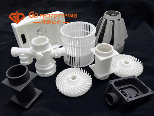
Injection moulding is a common manufacturing process by injecting molten plastic material into a mould so that it can be formed into the desired product shape upon cooling.
Injection moulding process has the advantages of low cost, high production efficiency and stable product quality to make it widely used in various industries. In this vast injection moulding market, there are three industries are particularly eye-catching, which are extensively used for production and manufacturing due to their specific needs and product characteristics.
1.Household Appliance Manufacturing Industry
As an indispensable part of people's daily life, the market demand for household appliances is stable and continuously growing. The injection moulding process plays a pivotal role in the manufacturing of household appliances, from the outer shell to the internal components, injection moulding technology provides key support. Most of the exterior and structural components of home appliances, such as TV remote controls, refrigerators, TV sets, air-conditioning panels, and washing machine shells, are manufactured by injection molding process.
2.Automotive Components Industry & Transportation Sector
With the booming development of the automotive industry, the auto components and parts market has ushered in unprecedented development opportunities. Components and parts such as automotive dashboards, door interior panels, bumpers, and lamp housings as well as a wide range of pipework and connections are made through the injection moulding process. These parts require not only high precision and good mechanical properties, but also need to meet the strict appearance requirements, which injection moulding process is precisely by virtue of its unique advantages, in this field to occupy a place. In addition, with the rise of new energy vehicles, injection moulded parts play an important role in the manufacturing of key components such as battery packs and motor housings.
3.Medical Device Industry
With the increasing emphasis on health, the market demand for medical devices continues to grow. In medical device manufacturing, the injection moulding process is used to produce disposable medical devices such as syringes, infusion tubes and surgical instruments. These products require strict quality control and hygiene standards, and injection moulding process ensures product safety and effectiveness.
In addition, the injection moulding process is also widely used in the electrical and electronic industry, consumer electronics, packaging industry, toy manufacturing, construction materials, industrial parts, furniture and household furnishings and agriculture, among many others.
4.Electrical & Electronic Industry
In the manufacturing process of electronic products, many components such as housings, cases, sockets, connectors, cables, switches and holders for electronic circuit boards need to be manufactured by injection moulding process. Injection moulding process can achieve precise control of product appearance, size and structure, to meet the requirements of electronic products for appearance quality, functionality and reliability.
5.Consumer Electronics Industry
In the electronics industry, injection moulded parts are equally widely used. From mobile phone housings, computer components including keyboards and mice to remote controls and battery cases, the injection moulding process offers a wide variety of appearance and structure options for electronic products. These components not only need to have good mechanical properties and appearance, but also need to have excellent electrical insulation properties to ensure the stable operation of electronic products. Injection moulding technology occupies an important position in the manufacture of electronic products due to its advantages of high precision and low cost.
6.Construction Sector
In the construction field, injection moulded parts also have a wide range of applications, the drainage systems, door and window frames, pvc pipes, valves, wire troughs, insulation materials and other construction materials and accessories are mostly manufactured by injection moulding process. These components are not only high-strength and corrosion-resistant, but also weather-resistant and easy to install, meeting the construction industry's requirements for material performance and ease of use and improve construction efficiency and aesthetics. The application of injection moulding technology in the construction field not only improves the performance and quality of construction materials, but also promotes the sustainable development of the construction industry.
7.Packaging Industry
The packaging and container industry is also one of the key application areas for injection moulding processes. Plastic bottles, food boxes, cosmetic bottles, plastic bags and other packaging containers are mostly manufactured by injection moulding process to meet food safety and aesthetic requirements. These containers need to be well-sealed, drop-resistant, retain freshness and recyclable to ensure that the products are safe and environmentally friendly. Injection moulding processes can offer flexible design and manufacturing options to adapt to different packaging needs and provide strong support for the development of the packaging industry.
These areas above are just a few examples of the application areas of the injection moulding process. In the toy industry, injection moulded parts are used to manufacture a variety of plastic toys; In the textile and clothing industry, injection moulded parts are used to manufacture accessories such as zips and buttons; In the agricultural sector, injection moulded parts are used to manufacture agricultural tools and equipment such as sprayers and watering cans; Even in the aerospace sector, injection moulded parts are also used to manufacture parts for aircraft and spacecraft. It can be said that injection moulded parts have penetrated into almost every corner of our life.
In summary, injection moulded parts play an important role in several industries by virtue of their high precision, low cost and wide applicability. The application of injection moulding process in these areas not only improves production efficiency, but also meets the needs of product diversification and individualisation. With the continuous progress of science and technology and the continuous improvement of people's requirements on product quality, injection moulding technology will continue to be widely used and developed in various fields.
#design#autos#business#prototyping#prototype#prototype machining#rapid prototyping#cnc machining#precision machining#machining parts#injection molding#plastic injection molding#injection moulding machine#injection moulding#plastic injection#injection molded#injection molding parts#injection molded parts
2 notes
·
View notes
Text
Seamless Mild Steel Tube At Lowest Price
Seamless mild steel tubes are a key component in numerous industrial applications due to their unmatched strength, durability, and ability to withstand high pressure. Whether you’re working in the construction industry, automotive sector, or manufacturing pipelines for oil and gas, seamless mild steel tubes provide reliability and performance.
What is a Seamless Mild Steel Tube?
A seamless mild steel tube is manufactured without any welding seams, making it exceptionally strong and resistant to corrosion. The absence of seams means the tube can handle higher pressure and is more uniform in structure, providing superior integrity and strength compared to welded tubes.
Benefits of Seamless Mild Steel Tubes
Strength and Durability: Seamless mild steel tubes are known for their robustness. Their lack of seams eliminates the weak points found in welded tubes, making them perfect for high-pressure applications.
Corrosion Resistance: Mild steel naturally resists corrosion, and seamless tubes offer an added level of protection in environments where exposure to chemicals or water is common.
Smooth Finish: Seamless tubes have a smooth internal and external finish, which not only enhances their aesthetic appearance but also improves fluid or gas flow, making them highly efficient in industries like oil and gas.
Versatility: These tubes can be used in a wide variety of industries, including automotive, construction, industrial equipment, and more. They are often used in pipelines, boilers, and mechanical systems.
Higher Pressure Tolerance: The seamless structure allows these tubes to withstand higher pressure, making them suitable for applications where strength and safety are paramount.
Applications of Seamless Mild Steel Tubes
Automotive Industry: Seamless mild steel tubes are widely used in vehicle components such as frames, shock absorbers, and exhaust systems due to their durability and strength.
Oil & Gas Pipelines: The oil and gas sector heavily relies on seamless tubes for high-pressure pipelines because of their ability to handle extreme temperatures and pressure.
Construction: In construction, seamless mild steel tubes are used for building frameworks, scaffolding, and support structures due to their load-bearing capabilities.
Boilers and Heat Exchangers: These tubes are ideal for high-temperature and high-pressure environments, like boilers and heat exchangers, where materials must withstand continuous stress.
Udhhyog: Your Trusted Supplier for Seamless Mild Steel Tubes
If you’re looking for reliable and high-quality seamless mild steel tubes, Udhhyog is your go-to partner. Udhhyog is a technology-driven platform that aims to simplify procurement for businesses across industries. They offer a wide range of products, including MS seamless pipes, flanges, and valves, ensuring you get the best quality materials at competitive prices.
At Udhhyog, you can find a wide selection of seamless mild steel tubes that meet stringent industry standards, providing the strength, durability, and performance your projects require.
Explore Udhhyog’s seamless pipe offerings here.
Whether you’re working on a high-pressure pipeline, building a skyscraper, or manufacturing automotive components, seamless mild steel tubes are the backbone of any project that demands strength, durability, and reliability. Partnering with suppliers like Udhhyog ensures you get quality materials that will last for years to come.
Why Choose Seamless Mild Steel Tubes?
By opting for seamless mild steel tubes, you are investing in long-term performance. Their strength, resistance to corrosion, and seamless design make them an indispensable choice for industries that rely on high-quality materials for critical applications.
#SeamlessMildSteelTube#MildSteelTubes#SteelTubeSupplier#SeamlessPipes#IndustrialTubes#Udhhyog#PipeSupplier#MSSeamlessTube#ConstructionMaterials#OilAndGasPipelines#AutomotiveIndustry#HighPressureTubes#DurableTubes#SteelProducts#B2BProcurement
4 notes
·
View notes
Text
Exporters of Stainless Steel 304 Pipes & Tubes: Global Supply
@manilaxmiindustrial : Manilaxmi Industrial
Explore the features, applications of Stainless Steel 304 Pipes & Tubes. This guide highlights their importance in various industries, emphasizing durability and corrosion resistance. Stainless Steel 304 Pipes, Stainless Steel 304 Tubes, SS 304 Pipes, SS 304 Tubes, Stainless Steel, Pipes, Tubes, Industrial Materials
Stainless Steel 304 is one of the most widely used and versatile types of stainless steel in the industry. Known for its exceptional corrosion resistance, durability, and aesthetic appeal, Stainless Steel 304 Pipes and Tubes are vital components in a variety of applications, spanning across multiple industries.
What is Stainless Steel 304?
Stainless Steel 304 belongs to the austenitic family of stainless steel, which is composed of 18-20% chromium and 8-10.5% nickel, along with other elements such as carbon, manganese, and silicon.
The high chromium content provides excellent corrosion resistance, while the nickel enhances its strength and toughness.
This combination makes Stainless Steel 304 a popular choice for pipes and tubes, particularly in environments where corrosion resistance is a critical factor.
Applications of Stainless Steel 304 Pipes & Tubes
Stainless Steel 304 Pipes and Tubes are used in a wide array of industries due to their adaptability. Some of the most common applications include:
Food and Beverage Industry: The hygienic properties of Stainless Steel 304 make it ideal for food processing, storage, and transportation. It is resistant to corrosion from food products, cleaning agents, and the wide range of temperatures involved in food production.
Chemical and Petrochemical Industries: Stainless Steel 304 can withstand harsh chemicals, making it a preferred material for chemical processing equipment and pipelines. Its resistance to acidic and alkaline solutions ensures longevity in these demanding environments.
Construction Industry: Stainless Steel 304 Pipes and Tubes are frequently used in architectural structures, particularly in areas where aesthetics and durability are important. Its resistance to weathering and corrosion makes it a suitable material for both interior and exterior applications.
Automotive Industry: The durability and strength of Stainless Steel 304 make it an excellent choice for automotive exhaust systems, fuel lines, and other components that require resistance to high temperatures and corrosion.
Pharmaceutical Industry: In environments where cleanliness is paramount, Stainless Steel 304 shines. Its non-reactive properties and ease of cleaning make it ideal for the pharmaceutical industry, especially in the manufacturing of medicines and medical equipment.
#Manilaxmi Industrial#manufacturers#exporters#suppliers#industrial#innovation#pipeaccessories#manilaxmiindustrial
3 notes
·
View notes
Text

• Ken Miles was born on November 1st of 1918 in Sutton Coldfield, England. During his early life he apprenticed at a British car manufacturer. During World War II, he worked in various duties that dealt with machinery and utilized his mechanical skills. He began motorcycle racing while in the service and this would continue after his tour. After World War II, he returned to the automobile industry and to automotive racing. He acquired a Frazer-Nash racer and installed a Ford V8-60 engine. It had mile success in local and club competition.

• In 1952 Ken Miles came to the United States where he accepted a position as service manager for an MG distributor in California. Later, he would became involved with a wide range of teams and races and have a profound influence on early American road racing. His skills as a driver and fabricator quickly evolved and he became legendary on the West Coast with his competitive Specials.
• Miles first racer (that he constructed) was in 1953, while working for Gough Industries. He had been racing MG TD's for Gough, but they were often outclassed by the competition. Gough helped Miles with creating a racer, though he was unable to provide cash. What Gough did provide was use of any MG or Morris and any stock spare part.
• Miles began work on the MG R-1. The frame was created from mild steel tubing and attached to MG Series "Y" independent front suspension. The rear was comprised of a live axle. Alfin aluminum drum brakes with two-wheel cylinders were used to provide the stopping power while a Morris Minor rack-and-pinion kept the vehicle in the drivers control.
• Under the hood was an experimental racing engine that had a 1466cc displacement size. The engine would later be used by MG for their MG TF 1500. The engine had twin SU carburetors and a 10.5:1 initial compression ratio. The compression ratio was later increased to 11.6:1. The 83 horsepower engine was mated to a stock MG TD transmission which sent the power to the rear wheels.
• The car was clothed in a hand-formed aluminum body. The overall weight of the vehicle was less than 1,230 pounds. The car made its inaugural appearance in 1953 at a rainy Pebble Beach. The car had not been tested but this did not seem to matter, as it emerged victorious. Throughout the next year, the car would win all of the races it was entered, except for two. Its racing career came to an end in 1954 at Pebble Beach, when it suffered mechanical difficulties and failed to finish the race. The flywheel bolts fractures which allowed the flywheel to come loose. This resulted in the engine over-revving and it threw a rod. The R-1 Miles Special's racing career had come to an end.
• The second Miles Special racer was constructed in similar fashion to the first, but incorporated many key mechanical and design changes. Many MG components were still utilized, such as the gearbox and 1466cc MG XPEG engine. The space frame chassis was constructed from one-inch steel tubing which was lighter than its predecessor, but still retained the structural rigidity. To reduce frontal area, the driving position was lowered by nearly four inches. Other techniques were used to reduce the frontal area. The engine was tilted down in the front which did much to achieve this goal.
• The car was narrow and low, which meant changes were needed to fit all the engine components in the engine bay. The MG intake manifolds were installed upside down which allowed the carburetors to be angled and fit under the hood. The design of the vehicle was similar to the MG TF. This was done for brand recognition and to help promote the MG line of vehicles. There were differences; the R-2 had an envelope body with fenders that flared up, and over, the front and rear wheels. In the front was an MG style grille with headlights on either side. The car was finished in British racing green.
• The car was given the nickname, the Flying Shingle. Its inaugural race was in 1955 at Willow Springs. It failed to finish the race. Many of the other races in which it entered, it emerged victorious. Among its accomplishments were first place finishes at Pebble Beach and Torrey Pines. Miles was doing well in small-bore racing, but the competition was consistently keeping pace. Soon, a new machine was needed.
• Miles acceptable a position at Johnny Von Neumann's Porsche dealership. He raced during the 1956 season in a Porsche 550 Spyder and began work on a new racing Special. With von Neumann providing a generous budget, and Porsche providing ample stock components, Miles was able to construct a proper, large-budget racer. Power came from a Porsche Carrera four-cam engine that displaced 1500cc. The chassis was a Cooper Bobtail with a modified nose. The suspension was an independent setup with drums in the front and rear. The body shell was constructed of aluminum which aided greatly in the vehicles low weight of just under 950 pounds.
• Near the close of 1956, the newly created Special was brought to Pomona where it was piloted by Miles to a second place finish. At Paramount Ranch, the car was driven to a class win in the 1500cc class, and beat-out the big-bore modified class as well. The car was raced in 1956 and for part of 1957 before the von Neumann dealership was given the break they had been desperately searching for - a Porsche 550A. The car was supplied from the factory with orders to sell the R-3 Pooper Special. The R-1, R-2, and R-3 are still in existence in modern times. They are used in vintage competition and are shown at events.
• Ken Miles life came to a tragic end on August 17th, 1966 while driving a Ford J-car prototype. The car was traveling at 175 mph on a back-strech. Ken began preparing for a corner, slowing the vehicle down, but it went out of control and over an embankment. Ken was thrown from the car as it spun and went end-over-end. This tragedy brought an end to a brilliant career that began during the very early 1950s.
16 notes
·
View notes
Text
The Versatility of Fiber Laser Cutting Machines in Steel Structure Processing
Versatile Fiber Laser Cutting Machines
The adaptability of fiber laser cutting machines, like the Lh 12012 00 12000w Steel Structure Production Line Tube Laser Cutting Machine, provides exceptional precision and efficiency in processing steel structures.
These machines offer high precision cutting for steel structures, ensuring accurate and clean edges.
Their advanced technology allows for intricate designs and detailed cuts, meeting the demands of various steel structure processing projects.
Precision and Efficiency
High Precision Cutting
When it comes to steel structure processing, the pipe laser cutting machine excels in providing high precision cutting. This ensures that the steel structures have accurate and clean edges, meeting the strict quality standards of the industry. The advanced technology integrated into these machines allows for the execution of intricate designs and detailed cuts, catering to the diverse requirements of various steel structure processing projects.
Efficient Production
The pipe laser cutting machine's efficient cutting process is designed to minimize material waste and enhance overall production efficiency. By incorporating zero tail material cutting, it optimizes resource utilization while minimizing operational costs. This not only contributes to cost savings but also aligns with sustainable manufacturing practices by reducing material wastage in metal materials cutting operations.
Industry Applications
In the construction industry, the tube laser cutting machine is a valuable asset for fabricating steel components with precision and efficiency. Its versatility enables the seamless processing of steel materials, contributing to the timely completion of construction projects. The machine's ability to handle various cross-section sizes makes it an ideal tool for meeting the diverse requirements of steel fabrication in construction.
In the automotive and manufacturing sectors, the tube laser cutting machine plays a crucial role in producing high-quality metal components and parts. Its precision cutting capabilities and efficient production process ensure that metal materials are processed accurately and efficiently. This contributes to enhancing overall productivity and meeting the stringent quality standards of these industries. The machine's adaptability to handle different cross-section sizes further solidifies its position as a valuable asset in meeting the diverse needs of automotive and manufacturing applications.
Automated Operations
Automatic Loading and Unloading
The integration of automatic loading and unloading capabilities in the tube laser cutting machine streamlines the entire production process. This advanced feature significantly reduces the need for manual labor, leading to a more efficient and cost-effective solution for large-scale steel structure processing. By automating the material handling aspect, this machine minimizes human intervention, thereby enhancing safety and operational efficiency.
Enhanced Productivity
The automated operations of the tube laser cutting machine contribute to a substantial increase in productivity while simultaneously reducing turnaround times. With minimal manual intervention required, the machine ensures consistent and reliable performance in metal materials cutting operations. This not only improves overall productivity but also allows for better resource allocation and optimized production scheduling.
Enhancing Steel Structure Processing
Fiber laser cutting machines play a pivotal role in enhancing the processing of steel structures across various industries. Their adaptability and precision offer efficient solutions for metal materials cutting operations, contributing to the seamless fabrication of steel components. The integration of automated operations further elevates productivity and reduces manual intervention, ensuring consistent and reliable performance. This advanced technology not only enhances the overall efficiency of steel structure processing but also aligns with sustainable manufacturing practices, making it an ideal choice for the construction industry and manufacturing sectors.
See Also
Top-notch Pipe Laser Cutting Machine Suppliers: A Comprehensive Guide
2 notes
·
View notes
Text
Blow Molding: Transforming Plastic into Innovative Products
Blow molding is a manufacturing technique for producing hollow plastic items. It is a flexible process capable of producing a wide range of plastic containers, bottles, automobile components, toys, and other items. The method is extremely cost-effective and efficient, making it a popular choice in a variety of sectors.

What Is the Process of Blow Molding?
Blow molding usually entails the following steps:
Extrusion is the process of melting plastic pellets and extruding them into a hollow tube, commonly known as a parison.
Mold Cavity: The parison is put in a mold cavity, which is frequently custom-designed to match the shape of the object.
Inflation: When air is introduced into the parison, it expands and takes on the shape of the mold.
Cooling: The plastic within the mold is allowed to cool and solidify.
The molded item is ejected from the mold.
Variations in Blow Molding
Blow molding from blow molding manufacturer comes in a variety of forms, including:
Extrusion Blow Molding (EBM) is the most prevalent form, and it is used to make bottles and containers.
Injection Blow Molding (IBM): This process is best suited for tiny, precise items like medical vials and some automotive components.
Stretch Blow Molding (SBM): A popular method for producing PET bottles, it provides better control over the finished product's properties.
Continuous Extrusion Blow Molding (CEBM): This technique is mostly utilized for the high-volume manufacture of smaller goods such as milk jugs.
Blow Molding Manufacturers' Role The heart of this business is made up of blow molding producers. They take raw materials and turn them into a diverse range of products that fulfill the demands of many sectors. Here's a deeper look at their key responsibilities:
Design on Demand: Blow molding manufacturers collaborate closely with clients to create unique molds that meet the product specifications.
Material Expertise: They have an extensive understanding of various plastic materials, ensuring that the appropriate material is selected for the intended use.
Precision Manufacturing: Blow molding companies use cutting-edge technology to accurately regulate factors like temperature, pressure, and cooling, resulting in consistent product quality.

Quality Control: Strict quality control methods guarantee that each product fulfills industry standards as well as customer specifications.
To keep ahead of market expectations, Blow molding manufacturer China continually innovates in terms of materials, processes, and designs.
2 notes
·
View notes
Text

die cast engine gearbox parts
Sebros manufactures High Pressure Die cast machined parts, Tubular components and Fabrication assemblies. We supply to major OEMs in India, USA, Canada, Mexico and Europe. The industries we serve are Automotive, Power, Oil & Gas, Chemical, Construction and Industrial hardware.
#https://sebrosgroupusa.com/Die cast parts#automotive tube components#hydroformed stainless steel bellows#die cast engine gearbox parts#door frames#bend pipes#radiator pipes
1 note
·
View note
Text
Automotive Component Manufacturing Experts | Metalman Auto Ltd.

Metalman Auto Ltd. stands as a Best Automotive Component Manufacturing Experts, delivering precision-engineered solutions to Original Equipment Manufacturers (OEMs) across the automotive industry. With over three decades of experience, we specialize in producing high-quality components for two-wheelers, three-wheelers, passenger vehicles, commercial vehicles, and off-highway vehicles, meeting the exacting standards of performance, reliability, and durability.
Our advanced manufacturing facilities are equipped with cutting-edge technologies, including CNC machining, metal stamping, tubular fabrication, and metal finishing. This allows us to offer a wide range of automotive components, from chassis parts to engine components and body panels. Each product is meticulously crafted to meet the specific needs of our OEM partners, ensuring seamless integration and optimal performance in their vehicles.
At Metalman Auto Ltd., quality is embedded in every step of our manufacturing process. We adhere to ISO-certified quality management systems and employ rigorous testing and inspection procedures to ensure that every component we produce meets or exceeds industry standards. Our commitment to excellence has earned us a reputation as a trusted partner for some of the most renowned names in the automotive industry.
Innovation is at the core of our operations. We continuously invest in research and development to stay ahead of industry trends and provide our clients with the most advanced automotive component solutions. Our team of skilled engineers and technicians works closely with OEMs to develop customized components that meet the unique challenges of today’s automotive market, from electric vehicles (EVs) to autonomous driving technologies.
Partner with Metalman Auto Ltd. to experience the expertise and reliability. best automotive component manufacturing experts. Explore our comprehensive range of services and discover how we can help you drive success in your automotive projects.
#OEM metal fabrication services#Custom metal parts manufacturer for OEMs#Bespoke metal fabrication for automotive industry#Custom metalwork for vehicle manufacturers#Precision metal fabrication for OEMs#Specialized metal fabrication for automotive parts#Tailored metal fabrication solutions for OEMs#Custom steel fabrication for automotive OEMs#Metal parts supplier for automotive industry#OEM metal components manufacturer#Automotive metal fabrication services#Steel and aluminum components for vehicles#Automotive metal body parts supplier#Precision metal parts for automotive applications#Automotive structural components manufacturer#OEM automotive metal components provider#Tube fabrication for automotive applications#Precision tube bending services#Tubular components manufacturer for OEMs#Automotive tubular parts fabrication#Custom tube fabrication for vehicles#Metal tube fabrication for automotive industry#Precision pipe fabrication services#Tubular assembly solutions for automotive OEMs#automotive tools#automotive industry#automotive innovation#automobile#automotive#crack in the chassis
1 note
·
View note
Text
Exploring the World of Leading Wire Harness Innovators
Wire harness manufacturers play a crucial role in various industries, providing essential components that ensure seamless connectivity and electrical integration in a wide array of applications. These manufacturers design and produce intricate wire harness systems tailored to specific requirements, adhering to strict quality standards and industry regulations.
For More Information Please visit, top wire harness manufacturers
key aspects of wire harness manufacturing
Industry Overview : Wire harness manufacturers operate in a highly competitive and evolving industry. They serve sectors such as automotive, aerospace, electronics, telecommunications, and healthcare, among others. The demand for custom wire harness solutions continues to grow as industries advance technologically.

Customization and Design : One of the significant aspects of wire harness manufacturing is customization. Manufacturers work closely with their clients to understand their unique needs. This involves designing wire harnesses that meet specific requirements, including size, shape, number of wires, insulation materials, and connector types.
Quality Assurance: Quality is paramount in wire harness manufacturing. Manufacturers invest in state-of-the-art testing equipment and employ skilled technicians to ensure that each harness meets the required standards. Rigorous testing procedures are in place to check for electrical continuity, insulation resistance, and overall durability.
Materials and Components: Wire harnesses consist of various materials and components, including wires, connectors, terminals, tubing, and insulation materials. Manufacturers carefully select these components based on the application's requirements, taking into account factors such as temperature, voltage, and environmental conditions.
Compliance and Certification: Wire harness manufacturers adhere to industry standards and regulations to guarantee the safety and performance of their products. Compliance with standards such as IPC/WHMA-A-620 ensures that the manufactured harnesses meet the necessary criteria for reliability and functionality.
Advanced Manufacturing Techniques : Modern wire harness manufacturing involves advanced techniques such as automated assembly, which enhances efficiency and precision. Computer Numerical Control (CNC) machines are employed for accurate cutting, stripping, and crimping of wires and connectors.
Supply Chain Management : Efficient supply chain management is crucial for timely production and delivery of wire harnesses. Manufacturers work closely with suppliers to source high-quality materials and components, ensuring a seamless flow of production.
Research and Development : Continuous research and development efforts drive innovation in the wire harness industry. Manufacturers invest in developing new materials, manufacturing processes, and technologies to improve the performance and longevity of wire harnesses.
Environmental Sustainability : Many wire harness manufacturers focus on sustainable practices, including the use of eco-friendly materials and recycling initiatives. Sustainability efforts contribute to reducing the environmental impact of manufacturing processes.

Conclusion
Wire harness manufacturers operate at the intersection of technology and precision engineering. Their commitment to quality, innovation, and customer satisfaction drives the industry forward, enabling seamless integration of electrical systems in various applications across the globe.
2 notes
·
View notes
Text
THE ULTIMATE GUIDE TO PRESSES, SHEARS, LASER CUTTERS AND PUNCHES
In the world of metal fabrication, several key machines play a vital role in shaping and cutting metal with precision and efficiency. This ultimate guide provides comprehensive knowledge and insights into the essential products of the industry: Press Brake, Press Brake Tools, Shearing Machine, Laser Cutting Machine, and Power Press. Whether you are a beginner or an experienced professional, this guide will equip you with the necessary information to understand, select, and optimize the use of these machines for your metalworking needs.
Press Brake:
1.What is a Press Brake?
A press brake is a key equipment used in the field of metal fabrication for bending and folding metal sheets. It utilizes pressure to bend the metal sheet into the desired shape. It is commonly used to create bent parts, enclosures, tubing, and other metal components.
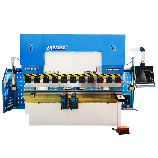
A press brake consists of an upper die and a lower die, with the upper die fixed to the frame and the lower die movable through a hydraulic system or mechanical drive system. The metal sheet is placed between the two dies and then bent into the desired angle and shape by applying pressure.
Press brakes typically have the following features and capabilities:
(1)Bending capacity: Press brakes can achieve bends at different angles and radii to meet various workpiece requirements.
(2)Precision: High precision bending results can be achieved by adjusting the position of the upper and lower dies.
(3)Automation: Some modern press brakes are equipped with CNC systems, allowing for automated operation and programming.
(4)Versatility: Press brakes can be used for various bending tasks and different types of metal materials by changing different tools and dies.
(5)Safety: Press brakes are typically equipped with safety devices such as light curtains, protective covers, and emergency stop buttons to ensure operator safety.
Press brakes are widely used in industries such as automotive manufacturing, aerospace, construction, electronics, and more. They are essential equipment for achieving precise and efficient metal fabrication.
2.Types of Press Brakes
There are several types of press brakes commonly used in metal fabrication:
Mechanical Press Brake: Uses a mechanical flywheel and clutch system for bending.
Hydraulic Press Brake: Utilizes hydraulic cylinders for precise bending control.
Servo-Electric Press Brake: Uses electric servo motors for high precision bending.
Pneumatic Press Brake: Relies on compressed air for lighter applications.
CNC Press Brake: Equipped with computerized controls for automated and precise bending operations.
The choice of press brake depends on factors such as material type, thickness, bending requirements, and production volume.
3.Components and Working Principles
A press brake consists of several key components that work together to perform the bending operation. Here are the main components and their functions:
Frame: The frame provides structural support and stability to the press brake.
Bed: The bed is a flat surface where the material to be bent is placed.
Ram: The ram is the moving part of the press brake that applies force to the material for bending.
Die: The die is a tool that shapes the material by providing a specific bending angle.
Punch: The punch is another tool that presses against the material, working in conjunction with the die to bend it.
Backgauge : The backgauge is an adjustable device that positions the material accurately for consistent bending.
4.Key Features and Benefits
Material Placement: The operator places the metal sheet or plate on the bed of the press brake.
Tool Setup: The appropriate die and punch are selected and installed on the press brake.
Backgauge Adjustment: The backgauge is adjusted to position the material correctly for the desired bend.
Bending Process: The ram moves downward, applying force to the material, which is sandwiched between the punch and the die. This bending action creates the desired angle in the material.
Material Removal: Once the bending is complete, the operator removes the bent material from the press brake.
5.Applications and Industries
Press brakes are widely used in various industries for different applications, including:
Metal Fabrication: Press brakes are commonly used in metal fabrication shops to bend and shape metal sheets and plates for various products such as enclosures, brackets, frames, and panels.
Automotive Industry: Press brakes are used in the automotive industry for manufacturing components like chassis, brackets, and body panels.
Aerospace Industry: Press brakes are utilized in the aerospace industry for bending and forming metal parts used in aircraft structures and components.
Construction and Architecture: Press brakes are used in the construction and architectural sectors for bending metal components used in building structures, facades, and decorative elements.
Electronics and Appliances: Press brakes are employed in the manufacturing of electronic enclosures, appliance components, and consumer products.
Press Brake Tools:
1.Importance of Press Brake Tools
Press brake tools play a crucial role in the performance and efficiency of press brake machines. Here are some key points highlighting the importance of press brake tools:
(1) Precision Bending: Press brake tools are designed to provide precise and accurate bending angles. They ensure consistent results and help meet the required specifications for the final product. The quality and precision of the tools directly impact the overall quality of the bent parts.
(2) Versatility: Press brake tools come in various shapes, sizes, and configurations to accommodate different bending requirements. They can be customized or interchanged to achieve different bending angles, radii, or complex shapes. This versatility allows manufacturers to produce a wide range of products using the same machine.
(3) Durability and Longevity: Press brake tools are made from high-quality materials such as hardened steel or special alloys, which make them highly durable and resistant to wear and tear. Proper maintenance and regular tool inspections ensure their longevity, reducing the need for frequent replacements.
(4) Efficiency and Productivity: Well-designed press brake tools optimize the bending process, reducing setup time, and increasing productivity. They enable faster bending cycles, allowing manufacturers to produce more parts in less time. Efficient tooling also minimizes material waste and improves overall production efficiency.
(5) Cost Savings: Using the right press brake tools can lead to cost savings in multiple ways. Accurate bending reduces material waste, saving on raw material costs. Efficient tooling reduces setup time and increases machine productivity, maximizing the output per hour. Additionally, durable tools have a longer lifespan, reducing the frequency of replacements and maintenance costs.
(6) Safety: Press brake tools are designed with safety features in mind. They provide proper clamping and holding mechanisms to secure the material during bending, minimizing the risk of accidents. Additionally, using high-quality tools reduces the chances of tool failure or breakage, ensuring operator safety.
(7) In summary, press brake tools are vital for achieving precise and accurate bending results, improving productivity, reducing costs, and ensuring operator safety. Selecting the right tools and maintaining them properly is essential for the efficient operation of press brake machines.

2.Types of Press Brake Tools (including ARC Press Brake Tools)
There are several types of press brake tools available, each designed for specific bending applications. Here are some common types of press brake tools:
V-Die: V-dies are the most commonly used press brake tools. They consist of a bottom die with a V-shaped groove and a punch with a matching V-shaped tip. V-dies are versatile and can be used for a wide range of bending angles and materials.
(1) Bottoming Die: Bottoming dies, also known as flat dies, have a flat surface instead of a V-shaped groove. They are used for achieving sharp bends or bending thicker materials where a tighter radius is required.
(2) Gooseneck Punch: Gooseneck punches have a curved shape that allows for deep and offset bends. They are commonly used for bending channels, boxes, and other complex shapes.
(3) Hemming Tool: Hemming tools are used for creating hems or flanges on the edge of a sheet metal part. They consist of a punch and die set that folds the material over itself to create a secure edge.
(4) Radius Tool: Radius tools, also known as radius punches or radius dies, are used for creating curved bends with a specific radius. They are available in various sizes to accommodate different bending requirements.
(5) Multi-V Die: Multi-V dies have multiple V-shaped grooves of different sizes on a single die. They allow for quick and easy tool changes without the need for separate dies for different bending angles.
(6) ARC Press Brake Tools: ARC press brake tools are specialized tools used for bending sheet metal into arc shapes. They are designed to create precise and consistent curved bends, commonly used in applications such as cylindrical parts, tubes, or curved profiles.
ARC press brake tools typically consist of a bottom die with a curved groove and a punch with a matching curved tip. They enable the accurate and repeatable bending of sheet metal into various arc shapes.
3.Material Selection and Coatings
When it comes to press brake tools, material selection and coatings play an important role in their performance and longevity. Here's a brief overview of material selection and coatings for press brake tools:
Material Selection:
(1) Tool Steel: Tool steel, such as D2 or A2, is commonly used for press brake tools due to its high hardness, wear resistance, and toughness.
(2) Carbide: Carbide inserts or tips are used for heavy-duty applications or when bending abrasive materials. Carbide provides excellent wear resistance but is more brittle than tool steel.
(3) High-Speed Steel (HSS): HSS is another option for press brake tools. It offers good toughness and wear resistance, but not as high as tool steel.
Coatings:
(4) Nitride Coating: Nitride coatings, such as TiN (Titanium Nitride) or TiCN (Titanium Carbonitride), improve the surface hardness and wear resistance of the tool. They are suitable for general-purpose bending applications.
(5) DLC Coating: DLC (Diamond-Like Carbon) coatings provide excellent hardness, low friction, and high wear resistance. They are ideal for bending stainless steel and other difficult-to-form materials.
(6) PVD Coating: Physical Vapor Deposition (PVD) coatings, like TiAlN (Titanium Aluminum Nitride), enhance the tool's performance by reducing friction and increasing wear resistance.
(7) Chrome Plating: Chrome plating is a common coating for press brake tools. It provides good corrosion resistance and reduces friction during bending operations.
The selection of material and coating depends on factors such as the type of material being bent, the bending application, and the desired tool life. It's important to choose the right combination of material and coating to ensure optimal performance and durability of the press brake tools.
4.Tooling Configurations and Considerations
When it comes to press brake tools, the tooling configurations and considerations are crucial for achieving accurate and efficient bending operations. Here are some important aspects to consider:
Tooling Configurations:
(1) V-Die: The V-die is the female tool that provides the desired bend shape. It comes in various widths and angles to accommodate different material thicknesses and bending requirements.
(2) Punch: The punch is the male tool that contacts the material and applies force to create the bend. It also comes in different shapes and sizes to achieve specific bend angles and radii.
(3) Multi-V Die: Multi-V dies have multiple V-shaped grooves of different widths and angles. They allow for bending different material thicknesses and angles without changing the die.
(4) Gooseneck Punch: Gooseneck punches have a curved shape that allows for deep or offset bends where space is limited.
(5) Hemming Tools: Hemming tools are used for creating hemmed edges or flanges on sheet metal.
Considerations:
(1) Material Thickness: The tooling configuration should be selected based on the material thickness being bent. Thicker materials may require larger tooling to accommodate the increased force and prevent tool damage.
(2) Material Type: Different materials have varying properties, such as hardness and ductility, which can affect the tooling selection. Harder materials may require tougher tooling materials or coatings.
(3) Bend Angle and Radius: The desired bend angle and radius dictate the selection of punch and die configurations. Sharp bends require smaller punch radii, while larger radii are needed for gentler bends.
(4) Tooling Alignment: Proper alignment between the punch and die is essential for achieving accurate and consistent bends. Misalignment can result in uneven bends or tool damage.
(5) Tooling Maintenance: Regular inspection and maintenance of the tooling are necessary to ensure optimal performance and longevity. This includes cleaning, lubrication, and replacement of worn-out components.
By considering the tooling configurations and these important factors, you can select the appropriate press brake tools for your specific bending requirements. This will help you achieve precise and efficient bending operations while prolonging the tooling life.
5.Tool Maintenance and Longevity
(1) Regular cleaning: Clean the press brake tools regularly to remove debris, dirt, and metal shavings. Use appropriate cleaning agents and tools to avoid damaging the tool surfaces. Ensure that the tools are completely dry before storing them.
(2) Lubrication: Apply lubrication to the press brake tools as recommended by the manufacturer. Lubrication helps reduce friction and wear, improving the tool's lifespan. Follow the manufacturer's guidelines for the type and frequency of lubrication.
(3) Inspection and repair: Regularly inspect the press brake tools for signs of wear, damage, or deformation. Check for any cracks, chips, or excessive wear on the cutting edges. If any issues are detected, promptly repair or replace the damaged parts to prevent further damage and ensure accurate bending results.
(4) Proper storage: Store the press brake tools in a clean and dry environment to prevent corrosion and damage. Use dedicated tool racks or boxes to keep the tools organized and protected. Avoid placing heavy objects on top of the tools to prevent deformation.
(5) Operator training: Proper training of operators is essential for tool maintenance and longevity. Educate operators on the correct usage techniques, operating limits, and safety precautions. Encourage operators to report any issues or abnormalities with the tools promptly.
By following these maintenance tips, you can extend the lifespan of your press brake tools and ensure consistent and accurate bending operations. Regular maintenance not only improves tool performance but also contributes to the overall safety and efficiency of the bending process.
6.Advanced Tooling Technologies and Innovations
Advanced tooling technologies and innovations have significantly improved the performance and capabilities of press brake tools. Here are some key advancements in press brake tooling:
(1) High-strength materials: Press brake tooling is now made from high-strength materials such as hardened steel alloys or carbide. These materials offer superior durability, wear resistance, and longer tool life compared to traditional tooling materials.
(2) Coatings and surface treatments: Advanced coatings and surface treatments, such as TiN (Titanium Nitride) or DLC (Diamond-Like Carbon), are applied to press brake tools to enhance their performance. These coatings reduce friction, improve wear resistance, and prevent material adhesion, resulting in improved bending quality and longer tool life.
(3) Precision tooling systems: Modern press brake tooling systems feature precision-ground tooling with tight tolerances. These systems ensure accurate and repeatable bending results, reducing setup times and increasing productivity.
(4) Quick-change tooling systems: Quick-change tooling systems allow for rapid tooling setup and changeovers. These systems utilize standardized tooling holders and clamping mechanisms, enabling operators to switch between different tooling setups quickly and efficiently.
(5) 3D modeling and simulation: Advanced software tools enable 3D modeling and simulation of bending processes. These tools help optimize tooling designs, simulate bending sequences, and detect potential collision or interference issues before actual production. This reduces setup time, minimizes errors, and improves overall efficiency.
(6) Custom tooling solutions: Tooling manufacturers now offer custom tooling solutions tailored to specific bending applications. These solutions include specialized tool profiles, custom tool coatings, and even tooling with integrated sensors for process monitoring and control.
These advancements in press brake tooling technologies have significantly improved productivity, accuracy, and tool life. By adopting these innovations, manufacturers can achieve higher efficiency, reduce downtime, and produce high-quality bent parts consistently.
Shearing Machine:
1.Understanding Shearing Machines
Shearing machines are industrial mechanical devices used for cutting metal sheets and other materials. They apply shearing force to cut the materials into desired shapes and sizes. Shearing machines are widely used in manufacturing and metalworking industries to produce various products and components.
The working principle of shearing machines involves placing the material on a shear table and applying force through cutting blades to cause the material to fracture. Shearing machines can perform operations such as straight cutting, curved cutting, and angle cutting. Depending on the specific requirements, shearing machines can have different cutting capacities and precision.
There are various types of shearing machines, including hydraulic shearing machines, mechanical shearing machines, and manual shearing machines. Hydraulic shearing machines use hydraulic systems to provide cutting force and offer high power and precision, making them suitable for large-scale and heavy-duty cutting tasks. Mechanical shearing machines use mechanical mechanisms to provide cutting force and are typically more compact and cost-effective, suitable for medium-sized cutting tasks. Manual shearing machines require manual operation and are suitable for small-scale and simple cutting work.
The cutting capacity of shearing machines depends on their maximum cutting thickness and cutting width. Larger shearing machines generally have higher cutting capacity and can handle thicker and wider materials. The cutting precision of shearing machines is influenced by factors such as blade sharpness, adjustment of blade clearance, rigidity of the frame, and material characteristics.
Safety considerations are important when operating shearing machines. Operators should receive proper training on the operation procedures and safety precautions of shearing machines. Additionally, appropriate personal protective equipment, such as safety goggles and gloves, should be worn. Regular inspection and maintenance of shearing machines are necessary to ensure their proper functioning and safe operation. Following the operation manual and manufacturer's recommendations is crucial to ensure the safety and effectiveness of operating shearing machines.
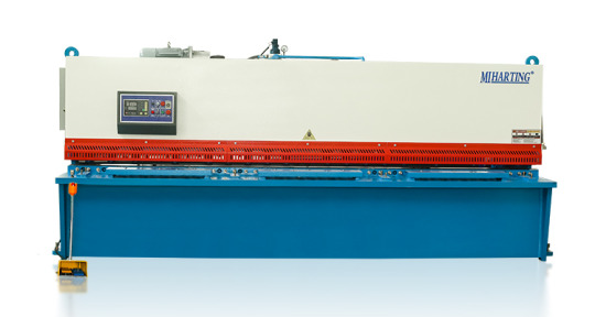
2.Hydraulic vs. Mechanical Shearing Machines
Hydraulic and mechanical shearing machines are two common types of shearing machines used in industrial applications. Here's a comparison between the two:
Power Source:
(1) Hydraulic Shearing Machines: These machines use a hydraulic system to generate the cutting force. The force is applied through hydraulic cylinders powered by a hydraulic pump. Hydraulic shearing machines offer high power and can handle heavy-duty cutting operations.
(2) Mechanical Shearing Machines: These machines use mechanical mechanisms, such as gears, levers, and flywheels, to generate the cutting force. The force is applied directly through the mechanical components. Mechanical shearing machines are generally more compact and cost-effective.
Power and Precision:
(1) Hydraulic Shearing Machines: Due to the hydraulic system, hydraulic shearing machines can provide high cutting power. They are capable of cutting thick and hard materials with precision. The hydraulic system allows for better control and adjustment of the cutting force, resulting in accurate and consistent cuts.
(2) Mechanical Shearing Machines: Mechanical shearing machines provide a lower cutting power compared to hydraulic ones. They are suitable for medium-duty cutting tasks. However, the cutting precision of mechanical shearing machines can be affected by factors such as mechanical wear and tear, which may require more frequent adjustments and maintenance.
Size and Space:
(3) Hydraulic Shearing Machines: Hydraulic shearing machines are generally larger and require more space due to the hydraulic system components, such as the hydraulic pump, cylinders, and hoses.
(4) Mechanical Shearing Machines: Mechanical shearing machines are more compact and take up less space. They are often preferred in smaller workshops or where space is limited.
Cost:
(1) Hydraulic Shearing Machines: Hydraulic shearing machines are typically more expensive due to the complexity and cost of the hydraulic system components.
(2) Mechanical Shearing Machines: Mechanical shearing machines are generally more affordable and cost-effective.
In summary, hydraulic shearing machines provide high power and precision, making them suitable for heavy-duty cutting operations. They are larger and more expensive. On the other hand, mechanical shearing machines are more compact, cost-effective, and suitable for medium-duty cutting tasks. The choice between hydraulic and mechanical shearing machines depends on the specific cutting requirements, available space, and budget considerations.
3.Components and Operation
Components of a Shearing Machine:
(1) Shear Table: This is the flat surface or bed on which the material to be cut is placed. It provides support and stability during the cutting process.
(2) Cutting Blades: These are the sharp blades that perform the actual cutting of the material. They are typically made of high-quality tool steel and are securely mounted on the machine. The blades can be straight, curved, or angled, depending on the desired cutting operation.
(3) Blade Clearance Adjustment: Shearing machines often have a mechanism for adjusting the clearance between the upper and lower blades. This adjustment allows for precise control of the cutting gap, ensuring clean and accurate cuts.
(4) Back Gauge: The back gauge is a movable stop or fence located behind the shear table. It helps in positioning the material accurately for repetitive cutting operations. The back gauge can be manually adjusted or controlled by a motorized system.
(5) Drive System: The drive system provides the power to move the cutting blades. In hydraulic shearing machines, the drive system consists of a hydraulic pump, cylinders, and valves. In mechanical shearing machines, it typically involves mechanical components such as gears, levers, and flywheels.
(6) Control Panel: The control panel houses the controls and switches for operating the shearing machine. It allows the operator to start and stop the machine, adjust settings, and monitor the cutting process.
Operation of a Shearing Machine:
(1) Material Preparation: The material to be cut is prepared by ensuring it is clean, straight, and properly aligned with the shear table. Any protective coatings or films on the material should be removed.
(2) Material Placement: The material is placed on the shear table, ensuring it is aligned with the back gauge if applicable. The operator should take care to position the material securely and avoid any obstructions that could interfere with the cutting process.
(3) Blade Clearance Adjustment: The blade clearance is set according to the thickness and type of material being cut. This adjustment ensures proper shearing without damaging the material or the blades. The manufacturer's guidelines or machine manual should be followed for the correct blade clearance settings.
(4) Cutting Operation: Once the material is properly positioned and the blade clearance is set, the operator initiates the cutting operation. In hydraulic shearing machines, the hydraulic pump is activated to provide the necessary cutting force. In mechanical shearing machines, the operator engages the drive system, which transfers power to the cutting blades.
(5) Monitoring and Control: During the cutting process, the operator monitors the operation to ensure smooth and accurate cutting. The control panel may provide indicators or displays for monitoring the cutting speed, blade position, and other parameters. Any abnormalities or issues should be addressed promptly.
(6) Material Removal and Repeat: After the cutting operation is complete, the cut pieces are removed from the shear table. The process can be repeated for subsequent cuts, adjusting the back gauge if necessary.
It's important to note that the specific operation of a shearing machine may vary depending on the machine model and manufacturer. Operators should always refer to the machine's manual and receive proper training before operating the shearing machine.
4.Cutting Capacity and Accuracy
Cutting Capacity and Accuracy are important considerations when using a shearing machine. Let's discuss each of them:
Cutting Capacity:
(1) Shearing machines have a specified cutting capacity, which refers to the maximum thickness and width of the material that can be effectively cut. The cutting capacity is determined by factors such as the power of the machine, the strength of the blades, and the rigidity of the shear table.
(2) It is crucial to choose a shearing machine with a cutting capacity that matches the requirements of the materials you will be working with. Attempting to cut materials beyond the machine's capacity can result in poor cutting quality, blade damage, or even machine malfunction.
Cutting Accuracy:
(1) Cutting accuracy refers to the ability of the shearing machine to make precise and consistent cuts. It is influenced by several factors, including the design and condition of the machine, the sharpness and alignment of the blades, and the control and monitoring systems.
(2) To achieve high cutting accuracy, it is important to maintain the shearing machine properly. Regular blade sharpening and replacement, as well as routine maintenance and calibration, can help ensure accurate cuts.
(3) The operator's skill and experience also play a significant role in achieving cutting accuracy. Proper material positioning, adjustment of blade clearance, and careful monitoring of the cutting process are essential for obtaining precise and clean cuts.
Factors Affecting Accuracy:
(1) Blade Condition: Dull or damaged blades can lead to uneven cuts and reduced accuracy. Regular inspection and maintenance of the blades are necessary to maintain cutting precision.
(2) Blade Clearance: Incorrect blade clearance can result in distorted or incomplete cuts. It is important to set the appropriate blade clearance for the material being cut.
(3) Material Alignment: Proper alignment of the material with the shear table and back gauge is crucial for accurate cuts. Misalignment can cause crooked or uneven cuts.
(4) Machine Rigidity: The rigidity of the shearing machine, including the shear table and frame, affects cutting accuracy. A sturdy and well-maintained machine provides better stability and reduces the chances of deflection during the cutting process.
It is recommended to follow the manufacturer's guidelines and recommendations for the specific shearing machine being used. Regular maintenance, blade inspection, and operator training are essential to ensure optimal cutting capacity and accuracy.
5.Safety Considerations
Safety considerations are of utmost importance when operating a shearing machine. Here are some key safety measures to keep in mind:
(1) Read and Follow the Manual: Familiarize yourself with the manufacturer's instructions and safety guidelines provided in the machine's manual. Understand the machine's features, controls, and potential hazards before operating it.
(2) Personal Protective Equipment (PPE): Always wear appropriate PPE, including safety glasses or goggles, gloves, and ear protection. Depending on the specific machine and the materials being cut, additional protective gear such as a face shield or apron may be required.
(3) Machine Inspection: Before starting the machine, inspect it for any signs of damage, loose parts, or malfunctioning components. Ensure that all safety guards and devices are in place and functioning correctly.
(4) Training and Competence: Only trained and authorized personnel should operate a shearing machine. Proper training should cover machine operation, safety procedures, emergency shutdown, and handling of materials.
(5) Material Handling: Use caution when handling materials, especially large or heavy ones. Use lifting equipment or assistance when necessary to avoid strain or injuries.
(6) Emergency Stop: Familiarize yourself with the location and operation of the emergency stop button or switch. Be prepared to use it in case of any emergency or unsafe situation.
(7) Blade Safety: Never reach into the cutting area while the machine is in operation or attempt to adjust the blades without proper training. Always wait for the machine to come to a complete stop before making any adjustments or maintenance.
(8) Housekeeping: Maintain a clean and organized work area. Remove any debris, scraps, or obstructions that may interfere with the machine's operation or cause accidents.
(9) Lockout/Tagout: Follow proper lockout/tagout procedures when performing maintenance or repairs on the machine. This involves disconnecting the power source and ensuring that it cannot be re-energized accidentally.
(10) Regular Maintenance: Adhere to the recommended maintenance schedule for the shearing machine. This includes blade sharpening, lubrication, and inspection of mechanical and electrical components.
Remember, safety should always be the top priority when operating any machinery. If you have any concerns or encounter any issues with the shearing machine, stop the operation immediately and seek assistance from a qualified technician or supervisor.
Laser Cutting Machine:
1.Introduction to Laser Cutting:
Laser cutting is a highly precise and versatile method of cutting various materials using a high-powered laser beam. It has revolutionized the manufacturing industry by providing a faster, more accurate, and more efficient alternative to traditional cutting methods. Laser cutting machines are used in a wide range of industries, including automotive, aerospace, electronics, signage, and jewelry making.

2.Types of Laser Cutting Machines:
There are different types of laser cutting machines available, each with its own advantages and suitable applications. The most common types include CO2 lasers, fiber lasers, and neodymium lasers.
CO2 lasers are the most widely used type of laser cutting machine. They use a mixture of carbon dioxide, nitrogen, and helium as the laser medium. CO2 lasers are versatile and can cut a wide range of materials, including non-metallic materials such as plastics, wood, and fabrics, as well as metals.
Fiber lasers use optical fibers as the laser medium. They are highly efficient and are primarily used for cutting metals, including stainless steel, aluminum, and copper. Fiber lasers offer high beam quality, which results in faster cutting speeds and improved precision.
Neodymium lasers use neodymium-doped crystals (such as neodymium-doped yttrium aluminum garnet or Nd: YAG) as the laser medium. They are known for their high energy and are used for precision cutting and engraving. Neodymium lasers are commonly used in applications that require high power and fine detail, such as jewelry making and micro-machining.
3.Advantages and Limitations:
Laser cutting offers several advantages over traditional cutting methods. One of the key advantages is its high precision and accuracy. Laser cutting machines can achieve intricate and complex cuts with minimal distortion. They also provide excellent edge quality, eliminating the need for additional finishing processes.
Another advantage is the speed and efficiency of laser cutting. Laser cutting machines can cut at high speeds, resulting in faster production times and increased productivity. They can also cut multiple parts simultaneously, further improving efficiency.
Laser cutting is a non-contact cutting method, which means there is no physical contact between the cutting tool and the material. This reduces the risk of damage to the material and allows for cutting delicate or fragile materials.
However, laser cutting does have some limitations. The thickness capacity of a laser cutting machine depends on the power of the laser and the type of material being cut. Thicker materials may require multiple passes or a more powerful laser to achieve a clean cut. Additionally, laser cutting machines can be expensive to purchase and maintain, making them more suitable for high-volume production environments.
4.Material Compatibility and Thickness:
Laser cutting machines can cut a wide range of materials, including metals, plastics, wood, textiles, and more. The compatibility of a material with laser cutting depends on its ability to absorb the laser energy. Materials that are highly reflective, such as copper or aluminum, may require higher laser power for cutting.
The thickness of the material that can be cut depends on the power of the laser and the type of material. Laser cutting machines can typically cut thin materials with high precision. For example, a CO2 laser cutting machine can cut up to 25mm thick steel, while a fiber laser cutting machine can cut up to 30mm thick steel. However, the maximum thickness capacity may vary depending on the specific machine and laser power.
It is important to consider the material compatibility and thickness capacity of a laser cutting machine before selecting the appropriate machine for a specific application. Consulting with a laser cutting machine supplier or manufacturer can help determine the best machine for a particular material and thickness requirement.
Power Press:
1.Exploring Power Press Machines:
Power press machines, also known as press machines or stamping presses, are versatile machines used in metalworking for various operations such as punching, bending, forming, and blanking. They are commonly used in industries such as automotive, manufacturing, construction, and appliance production. Power press machines come in different sizes and configurations to accommodate different applications and production requirements.
Power press machines are designed to apply force to a workpiece using mechanical or hydraulic systems. They are capable of exerting high pressure to shape, cut, or form metal sheets or other materials. Power press machines can be categorized into mechanical and hydraulic types based on their power source and operation.
2.Mechanical vs. Hydraulic Power Press:
Mechanical power presses use mechanical force, typically generated by a flywheel and a crankshaft, to perform operations. They are known for their high speed and productivity. Mechanical power press machines have a mechanical clutch or brake system that controls the stroke and stopping motion of the ram. They are suitable for high-volume production environments where speed and precision are important.
Hydraulic power presses, on the other hand, use hydraulic systems to generate force. They utilize hydraulic cylinders to apply pressure to the ram and perform operations. Hydraulic power press machines offer more control and flexibility in terms of force adjustment and speed modulation. They are often used for operations that require precise force control or for applications that involve deep drawing or forming of materials.
The choice between a mechanical or hydraulic power press depends on the specific requirements of the application. Factors such as the type of operation, material thickness, production volume, and precision requirements should be considered when selecting the appropriate power press machine.
3.Components and Operation:
Power press machines consist of several key components that work together to perform various operations. These components include the frame, slide or ram, bolster, die, clutch or brake system, and control system.
The frame provides the structure and support for the machine. It is usually made of cast iron or steel to withstand the forces exerted during operation. The slide, also known as the ram, moves up and down to apply force to the material. It is guided by the frame and can be driven by a crankshaft or hydraulic cylinders.
The bolster is a flat surface on which the material is placed. It provides support to the workpiece during the operation. The die is a specially shaped tool that performs the desired operation, such as punching a hole or bending a metal sheet. The die is mounted on the bolster or the ram, depending on the type of operation.
The clutch or brake system controls the stroke and stopping motion of the ram. In mechanical power press machines, a mechanical clutch or brake is used to engage or disengage the flywheel, controlling the motion of the ram. In hydraulic power press machines, the hydraulic system controls the movement of the ram.
The control system of a power press machine can vary depending on the specific machine and its features. It can range from simple manual controls to advanced computer numerical control (CNC) systems. CNC systems offer precise control over the machine's operation, allowing for programmable and repeatable processes.
4.Punching, Bending, and Forming Capabilities:
Power press machines are capable of performing various operations, depending on the tooling and dies used. Some common operations include punching, bending, forming, blanking, coining, embossing, and deep drawing.
Punching is a process of creating holes or shapes in a material using a punch and die set. Bending is the process of deforming a material to form angles or curves. Forming involves shaping a material to create three-dimensional objects or complex geometries. Blanking is the process of cutting out a flat shape from a larger piece of material. Coining is a process that involves compressing a material to create a precise shape or pattern. Embossing is the process of creating raised or depressed
Conclusion:By delving into the comprehensive knowledge provided in this ultimate guide, you have gained a solid understanding of Press Brake, Press Brake Tools, Shearing Machine, Laser Cutting Machine, and Power Press. Armed with this knowledge, you can confidently select, operate, and optimize these machines to achieve precise and efficient metal fabrication results. Remember to prioritize safety, regular maintenance, and stay updated with the latest advancements in the industry to stay ahead in the ever-evolving world of metalworking.
https://www.mihating.com/

3 notes
·
View notes
Text
Exploring Different Types of Square Pipes and Their Uses
Square pipes have become essential components in various industries due to their unique shape and strong qualities. The amalgamation of their geometric configuration and remarkable durability makes them well-suited for a diverse range of applications. This blog post provides a complete analysis of the many square pipes that are currently accessible in the market. It examines their distinct properties and the wide array of industries in which they are utilised. Elevate your structures with reliable square pipes by Tube Trading Co., your trusted partner and Square pipes supplier in Gujarat!
Mild Steel Square Pipes:
Mild steel square pipes, also known as MS square pipes, hold a significant presence within the construction and industrial sectors. The reasons for their widespread acceptance can be ascribed to their cost-effectiveness, durability, and simplicity in production. These pipes are widely utilised in the fabrication of frames, supports, and diverse structural components.
In addition to their application in construction, MS square pipes are commonly employed in the fabrication of furniture, racks, and fences owing to their notable pliability and corrosion resistance. Due to their wide range of applications, these entities are considered vital assets in various initiatives, spanning from architectural ventures to industrial infrastructure development.
Stainless Steel Square Pipes:
Stainless steel square pipes are widely recognised for their remarkable resistance to corrosion and their pleasing visual characteristics. These pipes have been utilised in architectural contexts, namely for embellishing handrails, balustrades, and other ornamental components. The exceptional capacity to withstand adverse weather conditions and exhibit resistance to corrosion renders them a very suitable option for outdoor applications.
In addition, sectors such as food processing and pharmaceuticals exhibit a preference for stainless steel square pipes owing to their hygienic characteristics and convenient maintenance. The integration of performance and aesthetics in these pipes renders them a highly desirable choice for applications that prioritise both endurance and visual appeal.
Aluminum Square Pipes:
Aluminium square pipes have emerged as a prominent choice due to their ability to achieve a harmonious equilibrium between strength, weight, and resistance to corrosion. The utilisation of these pipes holds considerable influence in sectors such as aerospace and automotive, where their favourable high strength-to-weight ratio is evident. The utilisation of aluminium square pipes in the construction industry yields advantages, as they facilitate the creation of structures and frames that are characterised by their lightweight nature.
Furthermore, their influence is evident within the renewable energy industry, specifically in the production of frameworks for solar panels. The inherent inertness of aluminium guarantees the durability of these structures, hence enhancing the sustainability of solar energy installations. Don't compromise on quality and strength, experience the difference with quality square pipes offered by Tube Trading Co. - an excellent Square pipe distributor in Vadodara!
PVC Square Pipes:
PVC square pipes have dominated the plumbing, irrigation, and drainage industries due to their low cost and high durability. These pipes are essential in water management systems and subterranean pipelines where corrosion is a major concern. PVC square pipes can be used as electrical conduits due to their insulating characteristics. Their importance in do-it-yourself (DIY) endeavours and the development of modular furniture is also not to be underestimated. PVC pipes are ubiquitous in the arts because of their adaptability and portability.
Carbon Steel Square Pipes:
Carbon steel square pipes are the go-to option when extreme durability and tensile strength are required. The oil and gas industry, among others, relies heavily on high-pressure applications, making these pipes an absolute necessity. Because of their high resistance to wear, they are particularly effective at transporting fluids and are also able to deal with abrasive materials. Carbon steel square pipes can be counted on for years to come, making them ideal for use in the production of long-lasting industrial machinery and equipment.
Galvanized Square Pipes:
When the primary issue is corrosion resistance, galvanised square pipes, which are strengthened by a zinc coating, become the focal point. These pipes are commonly utilised in external structures such as fences, handrails, and signage. In areas with elevated humidity levels or frequent contact with seawater, the galvanised coating serves as a defensive barrier, preventing corrosion and extending the durability of the pipes. The cost-effectiveness of their endurance results in a reduction in maintenance requirements and enhances the structural integrity of buildings.
Final Thoughts:
The realm of square pipes offers a wide range of possibilities, accommodating the unique requirements of different sectors. The diverse range of materials, such as mild steel with its utilitarian strength, stainless steel with its elegant properties, aluminium with its lightweight appeal, and PVC with its corrosion-resistant utility, each possess distinct characteristics that contribute to their individual merits.
In addition, carbon steel and galvanised pipes are designed to meet specific needs, hence improving the performance and durability of various buildings and systems. The examination of square pipes elucidates not only their tangible achievements but also their vital role in the advancement of contemporary infrastructure and architecture on a global scale. Crafting Gujarat's infrastructure with excellence. Choose Tube Trading Co. – a renowned Square pipe dealer in Vadodara as your square pipes partner!
#Square pipes Supplier in Vadodara#Square pipes Supplier in Gujarat#Square pipe distributor in Vadodara#Square pipe dealer in Vadodara#Business#Supplier#Distributor#Jindal pipes#Steel industry#Steel company#Construction structure
8 notes
·
View notes