#Design Optimization
Explore tagged Tumblr posts
Visit Tumblr Blog
Explore Tumblr blogs with no restrictions, modern design and the best experience.
Last Seen Tumblr Blogs


Fun Fact
BuzzFeed published a report claiming that Tumblr was utilized as a distribution channel for Russian agents to influence American voting habits during the 2016 presidential election in Feb 2018.
Text

In today’s competitive landscape, bringing innovative ideas to fruition requires a blend of creativity and technical expertise. Inventor Modeling Services have emerged as a critical resource for engineers, product designers, and manufacturers looking to transform concepts into precise 3D models. Utilizing advanced software tools, these services streamline the design process, enhance product quality, and reduce time to market.
Understanding Inventor Modeling
Inventor modeling refers to the process of creating three-dimensional representations of products or components using Autodesk Inventor, a powerful 3D CAD software. This software enables users to design, visualize, and simulate how a product will function in the real world. The modeling process encompasses various stages, including conceptualization, design, and analysis, ensuring that every aspect of a product is meticulously crafted.
Detailed 3D Modeling
Precision in Design: Inventor modeling services enable the creation of highly detailed 3D models that accurately represent dimensions, materials, and finishes. This precision is vital for ensuring that products meet design specifications and functional requirements.
Parametric Modeling: The parametric capabilities of Autodesk Inventor allow for dynamic modeling, where changes in one part of the design automatically update related components. This feature simplifies the process of making adjustments, saving time and reducing errors.
Enhanced Visualization
Realistic Renderings: Inventor modeling services can generate photorealistic renderings of products, providing stakeholders with a clear visualization of the final outcome. This visual clarity aids in decision-making and enhances presentations to clients or investors.
Virtual Prototyping: With Inventor modeling, teams can create virtual prototypes that simulate the functionality of a product. This process helps identify potential design flaws and performance issues before physical prototypes are developed, saving time and resources.
Streamlining the Design Process
In an era where speed and efficiency are paramount, inventor modeling services streamline the design process in several ways:
Rapid Iteration and Prototyping
Quick Design Modifications: The flexibility of Inventor allows designers to make rapid modifications to their models. This capability is crucial for responding to client feedback or addressing unforeseen design challenges without starting from scratch.
Testing and Simulation: Autodesk Inventor includes powerful simulation tools that enable teams to test the performance of their designs under various conditions. This testing ensures that products will function as intended, reducing the risk of failure after launch.
Collaboration and Integration
Seamless Collaboration: Inventor modeling services promote collaboration among team members, enabling engineers, designers, and manufacturers to work together effectively. The ability to share 3D models facilitates communication and helps ensure that all stakeholders are aligned throughout the design process.
Integration with Other Software: Autodesk Inventor can integrate with other software tools, such as project management and manufacturing systems. This integration allows for seamless data transfer and ensures that everyone has access to the most up-to-date information.
Cost-Effectiveness and Risk Mitigation
Investing in inventor modeling services can lead to significant cost savings and risk reduction:
Minimized Production Costs
Reducing Material Waste: Accurate modeling helps optimize material usage, minimizing waste during production. By ensuring that designs are efficient and effective, companies can save money on raw materials.
Streamlining Manufacturing Processes: Detailed models enable manufacturers to plan their production processes more effectively. By understanding the complexities of a design upfront, manufacturers can optimize workflows and reduce labor costs.
Early Identification of Design Flaws
Proactive Problem Solving: The simulation and analysis capabilities of Inventor allow teams to identify potential issues early in the design process. By addressing these flaws before they reach production, companies can avoid costly rework and delays.
Compliance and Standards Adherence: Inventor modeling services ensure that designs meet industry standards and regulations. This adherence helps mitigate the risks associated with non-compliance, which can result in legal issues and financial penalties.
Supporting Innovation and Customization
As industries become more competitive, the demand for innovative and customized solutions is on the rise. Inventor modeling services support this trend by enabling:
Tailored Designs
Customization for Specific Needs: Inventor modeling allows for the creation of customized designs that cater to specific client requirements. This customization can differentiate products in a crowded market and enhance customer satisfaction.
Flexible Design Options: The parametric nature of Inventor models allows for easy modifications, enabling designers to explore various configurations and options. This flexibility fosters creativity and innovation in the design process.
Rapid Prototyping for Innovation
Accelerating the Innovation Cycle: With the ability to quickly create and modify models, teams can rapidly prototype new ideas. This acceleration allows companies to test and refine concepts, leading to more innovative products and solutions.
Responding to Market Trends: The agility provided by inventor modeling services enables companies to respond quickly to changing market demands. By rapidly adapting designs, businesses can stay ahead of competitors and meet evolving customer needs.
Conclusion
In conclusion, Inventor Modeling Services are essential for transforming innovative ideas into functional and market-ready products. By leveraging the capabilities of Autodesk Inventor, companies can achieve precise, efficient, and customizable designs that meet the demands of today’s competitive landscape.
Investing in expert inventor modeling services not only streamlines the design process but also enhances collaboration, minimizes costs, and supports innovation. As businesses continue to seek ways to differentiate themselves and improve efficiency, embracing inventor modeling will remain a critical strategy for success in design and manufacturing. Whether you are developing a new product or refining an existing design, inventor modeling services provide the foundation needed to turn visions into reality.
1 note
·
View note
Text
Little P.Eng.'s Comprehensive Seismic Structural Services Aligned with ASCE 7-22 and NBCC Standards
In an era where architectural ambition pushes the limits of engineering, safeguarding structural integrity against natural calamities, particularly seismic activities, becomes paramount. This detailed exposé delves into the sophisticated seismic structural engineering services provided by Little P.Eng., a firm renowned for its compliance with the latest American Society of Civil Engineers (ASCE) 7-22 standards and the Canadian National Building Code (NBCC). Their work spans across Canada and the United States, encompassing a diverse range of buildings and non-structural elements, reflecting the pinnacle of safety, reliability, and innovation in modern construction.
1. Introduction
The unpredictable nature of seismic activities has long posed a significant challenge to the realms of construction and civil engineering. Within this volatile environment, Little P.Eng. has emerged as a beacon of reliability, offering cutting-edge seismic structural engineering services across Canada and the United States. Their adherence to the ASCE 7-22 and NBCC codes ensures not only the structural integrity of vast construction undertakings but also the safety and longevity of non-structural elements, affirming their position at the forefront of seismic resilience in contemporary infrastructure.
2. Understanding Seismic Structural Engineering
2.1. The Science of Earthquake Engineering
Before delving into Little P.Eng.'s specialized services, one must understand the core principles of seismic structural engineering. This discipline focuses on making buildings and non-structural components resistant to earthquake shocks through specialized planning, design, detailing, and, subsequently, construction. It encompasses geological science, material engineering, and structural analysis to develop structures capable of withstanding seismic disturbances.
2.2. Evolution of Seismic Codes: From ASCE 7-10 to ASCE 7-22
Seismic building codes are dynamic, evolving in response to the continuous advancements in engineering research and catastrophic lessons learned from each seismic event. The transition from ASCE 7-10 to ASCE 7-22 is a reflection of this evolution, marking significant strides in risk reduction and structural robustness, emphasizing not just human safety but also post-earthquake functionality and rapid recovery for communities.
3. Little P.Eng.’s Integration of ASCE 7-22 in Seismic Structural Engineering
3.1. Innovations in Seismic Design Philosophies
Little P.Eng. employs a forward-thinking approach to integrate the innovations outlined in ASCE 7-22. These include state-of-the-art seismic design philosophies involving base isolation, energy dissipation devices, and performance-based seismic design (PBSD), allowing for structures that are more flexible, absorb and dissipate seismic energy, and maintain structural integrity during earthquakes.
3.2. Site-Specific Hazard Analysis and Geotechnical Considerations
One of the critical aspects of ASCE 7-22 is the emphasis on site-specific hazard analyses. Little P.Eng.'s engineers led by Meena Rezkallah carry out comprehensive geotechnical evaluations, considering soil-structure interaction, liquefaction potential, and site-specific seismic hazard assessments. By understanding the geological variances across different regions in North America, they ensure that each design is intrinsically aligned with its environmental context.
4. Adherence to NBCC Standards: Expanding Safety Parameters Across Canada
4.1. Bridging Policies between Countries
While their services in the United States predominantly adhere to ASCE standards, Little P.Eng. seamlessly bridges engineering policies between the U.S. and Canada by aligning their practices with the NBCC. This code compliance not only underscores their versatility in handling cross-border projects but also reflects their commitment to upholding the highest safety and professional standards in every geographical locale.
4.2. Understanding NBCC’s Seismic Provisions
The NBCC has distinct seismic provisions, necessitating specialized knowledge and an adaptive engineering approach. Little P.Eng.'s expertise in Canadian seismic codes ensures that structural and non-structural components comply with regional regulations, catering to Canada's unique seismic challenges, especially in high-risk provinces.
5. Comprehensive Services for Buildings and Non-Structural Elements
5.1. Diverse Building Typologies
Little P.Eng.'s portfolio encompasses a variety of buildings, from residential high-rises and expansive commercial complexes to critical facilities like hospitals and emergency response centers. Each building type presents unique challenges, and the firm’s nuanced, context-oriented approach to seismic retrofitting and sustainable design practices sets industry standards.
5.2. Protecting Non-Structural Components
Beyond the buildings themselves, Little P.Eng. extends its engineering prowess to safeguard non-structural elements. These components, often overlooked, can pose significant hazards during seismic events. From architectural elements to mechanical and electrical systems, the firm implements exhaustive strategies to enhance the safety of these components, thereby protecting human life and minimizing economic loss.
6. Future Directions and Continuous Advancements
6.1. Embracing Technological Innovations
As the field of seismic structural engineering advances, Little P.Eng. remains committed to incorporating new technologies, including artificial intelligence and machine learning, for predictive analysis, design optimization, and risk management. Their continual investment in technology positions them as a leader in future-proofing structures against earthquakes.
6.2. Contribution to Global Seismic Safety Standards

Harnessing Advanced Engineering: Little P.Eng.'s Comprehensive Seismic Structural Services Aligned with ASCE 7-22 and CNBCC Standards in North America
7. Conclusion
Little P.Eng.’s comprehensive seismic structural engineering services, grounded in the latest ASCE and NBCC standards, represent a confluence of scientific mastery, innovative engineering, and a deep commitment to safeguarding human lives and investments. Their work across diverse building typologies and non-structural components in Canada and the United States cements their stance as a pivotal player in shaping resilient, sustainable, and safe urban landscapes. As seismic activity remains an unpredictable threat, the foresight and innovation of firms like Little P.Eng. are society's best bet for a safer tomorrow.
References
[1] American Society of Civil Engineers. (2022). Minimum Design Loads and Associated Criteria for Buildings and Other Structures (ASCE/SEI 7-22). ASCE.
[2] National Research Council Canada. (2020). National Building Code of Canada.
Tags:
Little P.Eng.
ASCE 7-22
design optimization
earthquake resilience
energy dissipation
building codes
seismic design
advanced materials
non-structural components
CNBCC
technological innovations
cross-border projects
geotechnical considerations
mechanical systems safety
base isolation
sustainable construction
electrical systems safety
Seismic structural engineering
critical infrastructure
artificial intelligence
urban resilience
construction techniques
seismic retrofitting
site-specific analysis
predictive analysis
professional standards
safety regulations
risk management
performance-based design
global seismic standards
Engineering Services
Structural Engineering Consultancy
Seismic Bracing Experts
Located in Calgary, Alberta; Vancouver, BC; Toronto, Ontario; Edmonton, Alberta; Houston Texas; Torrance, California; El Segundo, CA; Manhattan Beach, CA; Concord, CA; We offer our engineering consultancy services across Canada and United States. Meena Rezkallah.
#Little P.Eng.#ASCE 7-22#design optimization#earthquake resilience#energy dissipation#building codes#seismic design#advanced materials#non-structural components#CNBCC#technological innovations#cross-border projects#geotechnical considerations#mechanical systems safety#base isolation#sustainable construction#electrical systems safety#Seismic structural engineering#critical infrastructure#artificial intelligence#urban resilience#construction techniques#seismic retrofitting#site-specific analysis#predictive analysis#professional standards#safety regulations#risk management#performance-based design#global seismic standards
0 notes
Text
#AR#VR#Augmented Reality#3d product modeling#3d product visualization#3d product design#Engineering Visualization#Mechanical Engineering#Architectural Visualization#Automotive Engineering#Engineering Trends#Visualization Technologies#Design Optimization
1 note
·
View note
Text
Unveiling the Power of 3D Visualization: Revolutionizing Engineering Applications
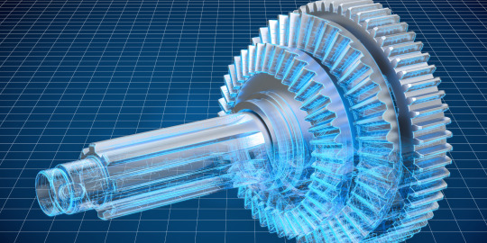
In the world of engineering, complex concepts and intricate designs often require effective means of communication to convey ideas, identify potential issues, and foster innovation. 3D visualization has emerged as a powerful tool that not only aids in comprehending intricate engineering concepts but also fuels creativity and enhances collaboration among multidisciplinary teams. This blog dives deep into the realm of 3D visualization for engineering applications, exploring its benefits, applications, and the technologies driving its evolution.
The Power of 3D Visualization
1. Enhanced Understanding: Traditional 2D drawings and diagrams can sometimes fall short in capturing the full complexity of engineering designs. 3D visualization empowers engineers, architects, and designers to create realistic and immersive representations of their ideas. This level of detail allows stakeholders to grasp concepts more easily and make informed decisions.
2. Identification of Design Flaws: One of the primary advantages of 3D visualization is its ability to identify potential design flaws before physical prototyping begins. Engineers can simulate real-world conditions, test stress points, and analyze the behavior of components in various scenarios. This process saves both time and resources that would have been wasted on rectifying issues post-construction.
3. Efficient Communication: When working on multidisciplinary projects, effective communication is essential. 3D visualization simplifies the sharing of ideas by presenting a clear visual representation of the design. This reduces the chances of misinterpretation and encourages productive discussions among team members from diverse backgrounds.
4. Innovation and Creativity: 3D visualization fosters creativity by enabling engineers to experiment with different design variations quickly. This flexibility encourages out-of-the-box thinking and exploration of unconventional ideas, leading to innovative solutions that might not have been considered otherwise.
5. Client Engagement: For projects involving clients or stakeholders who might not have technical expertise, 3D visualization serves as a bridge between complex engineering concepts and layman understanding. Clients can visualize the final product, making it easier to align their expectations with the project's goals.
Applications of 3D Visualization in Engineering
1. Architectural Visualization: In architectural engineering, 3D visualization brings blueprints to life, allowing architects to present realistic walkthroughs of structures before construction. This helps clients visualize the final appearance and make informed decisions about design elements.
2. Product Design and Prototyping: Engineers can use 3D visualization to create virtual prototypes of products, enabling them to analyze the functionality, ergonomics, and aesthetics. This process accelerates the design iteration phase and reduces the number of physical prototypes required.
3. Mechanical Engineering: For mechanical systems, 3D visualization aids in simulating motion, stress analysis, and assembly processes. Engineers can identify interferences, optimize part arrangements, and predict system behavior under different conditions.
4. Civil Engineering and Infrastructure Projects: From bridges to roadways, 3D visualization facilitates the planning and execution of large-scale infrastructure projects. Engineers can simulate traffic flow, assess environmental impacts, and optimize structural design for safety and efficiency.
5. Aerospace and Automotive Engineering: In these industries, intricate designs and high-performance requirements demand rigorous testing. 3D visualization allows engineers to simulate aerodynamics, structural integrity, and other critical factors before manufacturing.
Technologies Driving 3D Visualization
1. Computer-Aided Design (CAD): CAD software forms the foundation of 3D visualization. It enables engineers to create detailed digital models of components and systems. Modern CAD tools offer parametric design, enabling quick modifications and iterative design processes.
2. Virtual Reality (VR) and Augmented Reality (AR): VR and AR technologies enhance the immersive experience of 3D visualization. VR headsets enable users to step into a digital environment, while AR overlays digital content onto the real world, making it ideal for on-site inspections and maintenance tasks.
3. Simulation Software: Simulation tools allow engineers to analyze how a design will behave under various conditions. Finite element analysis (FEA) and computational fluid dynamics (CFD) simulations help predict stress, heat transfer, and fluid flow, enabling design optimization.
4. Rendering Engines: Rendering engines create photorealistic images from 3D models, enhancing visualization quality. These engines simulate lighting, materials, and textures, providing a lifelike representation of the design.
Future Trends and Challenges
As technology evolves, so will the field of 3D visualization for engineering applications. Here are some anticipated trends and challenges:
1. Real-time Collaboration: With the rise of cloud-based tools, engineers worldwide can collaborate on 3D models in real time. This facilitates global teamwork and accelerates project timelines.
2. Artificial Intelligence (AI) Integration: AI could enhance 3D visualization by automating design tasks, predicting failure points, and generating design alternatives based on predefined criteria.
3. Data Integration: Integrating real-time data from sensors and IoT devices into 3D models will enable engineers to monitor performance, identify anomalies, and implement preventive maintenance strategies.
4. Ethical Considerations: As 3D visualization tools become more sophisticated, ethical concerns might arise regarding the potential misuse of manipulated visualizations to deceive stakeholders or obscure design flaws.
In conclusion, 3D visualization is transforming the engineering landscape by enhancing understanding, fostering collaboration, and driving innovation. From architectural marvels to cutting-edge technological advancements, 3D visualization empowers engineers to push the boundaries of what is possible. As technology continues to advance, the future of engineering will undoubtedly be shaped by the dynamic capabilities of 3D visualization.
#3D Visualization#Engineering Visualization#CAD Software#Virtual Reality (VR)#Augmented Reality (AR)#Design Innovation#Visualization Tools#Product Design#Architectural Visualization#Mechanical Engineering#Civil Engineering#Aerospace Engineering#Automotive Engineering#Data Integration#Real-time Visualization#Engineering Trends#Visualization Technologies#Design Optimization
1 note
·
View note
Text

A whole new meaning to Gay Chicken.
(For: Anonymous raffle winner!)
#poorly drawn mdzs#mdzs#wei wuxian#lan wangji#This prompt was super cute! Thank you for donating to the raffle!#And thank you to everyone who also donated!#Okay full disclosure I am on very little sleep right now so these next thoughts may be incomprehensible.#(That hasn't stopped me before. Sometimes the voices of the hat man give me good ideas.)#I have been vibrating with excitement for when we finally get to the chicken scene.#Because I really want to draw chickens! I love chickens! They are so optimally shaped for maximal cuteness.#That's a creature that was designed to be fluffy and sit on things. What is there to *not* love!#I know there is more significance to the whole exchange but really...I think Lan Wangji deep down just wants to hold cute creatures.#His hands are big and gentle and not meant for swords! They are made to be filling rabbit hutches with fresh hay and petting chickens.#This is to say; Lan Wangji's problems could all have been avoided if he was a farmboy.#He can still be a farmer. The two of them could run off into the country and start something new.#"True love is possible only - in the next world - for new people” Is a disco elysium quote I think about for wangxian all the time.#Ah but that's a different tangent. Look forwards to more art tomorrow!
1K notes
·
View notes
Text
Can AI Revolutionize 3D Concrete Printing? Exploring the Future of Construction
Introduction The field of construction is undergoing a transformative revolution with the advent of 3D concrete printing technology. This cutting-edge approach promises faster, cost-effective, and eco-friendly construction, revolutionizing the way we build structures. Now, the convergence of artificial intelligence (AI) with 3D concrete printing is pushing the boundaries even further, introducing…

View On WordPress
#3D Concrete Printing#Additive Manufacturing#AI#AI integration#AI-driven Construction#Architecture#artificial intelligence#Building Efficiency#Collaborative Robotics#construction#Construction Automation#construction industry#Construction Revolution#Construction Trends#Cost of Implementation#Data Privacy#Design Optimization#Eco-friendly Construction#future of construction#innovation#Material Selection#Predictive Maintenance#quality control#Real-Time Monitoring#Regulatory Compliance#Robotics#Security#Smart Robotic Systems#Sustainable Building#Sustainable Construction
0 notes
Text


now i'm sure that it's true

#steven universe#lapidot#lapis lazuli#su lapis#peridot#su peridot#fanart#my art#art#p#pp#digital#character art#2024#my posts#please dear god zoom in. it is so not optimized for tumblr format#also please ignore that i colored her knees wrong#i was hubristic i thought i had their designs memorized lkdsjf
1K notes
·
View notes
Text


various star rail doodles + a comic
#hsr#honkai star rail#acheron#aventurine#sunday#robin#black swan#stelle#welt#2.1 spoilers#<-lmao#do i tag everybody. i guess#tagged everyone in at least 2 drawings at least lol. went way over 5 tags so not all that useful but shrugs#my art#comics#(i dont actually use march in my acheron team. except when i had to fight aventurine because her ult is aoe lmao) (and he resists img anywa#so welt would be kindof not optimal lol)#this is my first time drawing like everybody here so bear with me. lmao. fuck drawing hoyo designs tbh
313 notes
·
View notes
Text


RARE PNG PAGE DECOR/WEBSITE ADDITIONS ETC - THE MOST ESOTERIC AND QUESTIONABLE TRANSPARENT GIF IMAGES FROM [REDACTED] PART 1
#page decor#rentry graphics#rentry resources#rentry decor#rentry stuff#carrd resources#carrd moodboard#carrd graphics#web graphics#pixel graphics#cute pixels#neocities#webcore#old web graphics#blinkies#stamps#decor#transparent png#png#pngfile#transparent#random pngs#gifset#multiple gifs#art#webmaster#web maintenance#website#website design#website optimization
166 notes
·
View notes
Text

my favorite part of the beta was how clueless player looked at everything
#kh#kingdom hearts#khml#kh missing link#kingdom hearts missing link#kh player#kh remus#keykid#stray (keykid)#<- future note: i didnt have a design for stray at this point so i just used sou's design instead#khml spoilers#just in case#anyway i heard that player joins the baroque society so i put them in matching outfits#remus the 頼れるお兄さん . the second i heard that it was over for me#i also dont believe in optimal posting times. its ass o clock in the early morning#myart
399 notes
·
View notes
Text
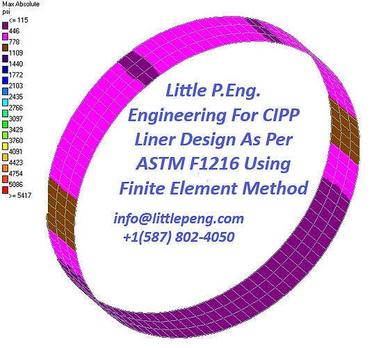
Little P.Eng. Engineering For CIPP Liner Design As Per ASTM F1216 Using Finite Element Method
In the realm of civil engineering, the rehabilitation of pipelines is a critical task that ensures the longevity and safety of underground infrastructure. One of the most innovative and efficient methods for pipeline rehabilitation is Cured-in-Place Pipe (CIPP) lining. This technique not only offers a less intrusive alternative to traditional pipeline repair but also significantly reduces the environmental impact and cost associated with excavation. Little P.Eng. Engineering, a pioneering firm in the engineering consultancy landscape, has taken strides in optimizing CIPP liner design to comply with ASTM F1216 standards through the application of the Finite Element Method (FEM).
Understanding ASTM F1216 and its Significance
ASTM F1216 is a standard that outlines the procedures for rehabilitating existing pipelines using the CIPP method. This standard is critical as it provides guidelines for the design, installation, and testing of CIPP liners, ensuring that rehabilitated pipelines meet specific safety and performance criteria. Compliance with ASTM F1216 is essential for any project involving CIPP lining, as it not only guarantees the structural integrity of the rehabilitated pipeline but also its longevity.
Little P.Eng. Engineering's Approach to CIPP Liner Design
Little P.Eng. Engineering has embraced the challenges of CIPP liner design by leveraging the Finite Element Method (FEM), a sophisticated computational technique that simulates how materials behave under various conditions. FEM allows engineers to model the complex interactions between the CIPP liner and the host pipe, taking into account factors such as material properties, external loads, and environmental conditions. By using FEM, Little P.Eng. Engineering can predict the performance of CIPP liners with high accuracy, ensuring that designs are not only compliant with ASTM F1216 but also optimized for durability and efficiency.
The Role of Finite Element Method in Ensuring Compliance and Optimization
The Finite Element Method plays a pivotal role in Little P.Eng. Engineering's design process by providing a detailed analysis of stress distribution, deformation, and potential failure points within the CIPP liner. This detailed analysis is crucial for two main reasons:
Compliance with ASTM F1216: FEM analysis helps ensure that the designed CIPP liner can withstand the intended service life under varying conditions, as stipulated by ASTM F1216. This includes assessing the liner's ability to handle internal pressures, ground movement, and other environmental factors without compromising its structural integrity.
Optimization of Design: Beyond compliance, FEM enables Little P.Eng. Engineering to optimize the thickness, material composition, and installation parameters of CIPP liners. This optimization not only reduces material costs but also minimizes the risk of over-engineering, ensuring that resources are used efficiently without sacrificing performance.
Case Studies and Success Stories
Conclusion
The innovative approach of Little P.Eng. Engineering to CIPP liner design, grounded in the rigorous application of the Finite Element Method and adherence to ASTM F1216 standards, represents a significant advancement in pipeline rehabilitation technology. This method not only ensures the structural integrity and longevity of CIPP liners but also exemplifies how engineering innovation can lead to more sustainable and cost-effective infrastructure solutions. As the demand for efficient and environmentally friendly rehabilitation methods grows, the work of Little P.Eng. Engineering in this field is set to become increasingly important, paving the way for future advancements in civil engineering practices.
Read More:
Innovating Pipeline Rehabilitation: Pipe CIPP Lining Engineering Design Services as per ASTM F1216
Pipeline Rehabilitation Engineering Design Services as per ASTM F1216 Using CIPP and PVC
Little P.Eng. Engineering For CIPP Liner Design As Per ASTM F1216 Using Finite Element Method
Revolutionizing Pipe Rehabilitation: Little P.Eng. Engineering's Mastery of CIPP Liner Design via Finite Element Method in Accordance with ASTM F1216
Tags:
Little P.Eng. Engineering
ASTM F1216
structural integrity
design optimization
engineering innovation
material properties
Finite Element Method
underground infrastructure
performance prediction
industry guidelines
CIPP liner design
material optimization
infrastructure longevity
safety criteria
environmental impact
maintenance cost reduction
pipeline rehabilitation
simulation techniques
performance criteria
durability assessment
compliance standards
computational modeling
non-invasive repair methods
failure point identification
sustainable solutions
installation parameters
stress distribution analysis
external loads
civil engineering practices
cost reduction
Engineering Services
•
Pipe Rehabilitation
Located in Calgary, Alberta; Vancouver, BC; Toronto, Ontario; Edmonton, Alberta; Houston Texas; Torrance, California; El Segundo, CA; Manhattan Beach, CA; Concord, CA; We offer our engineering consultancy services across Canada and United States. Meena Rezkallah.
#Little P.Eng. Engineering#ASTM F1216#structural integrity#design optimization#engineering innovation#material properties#Finite Element Method#underground infrastructure#performance prediction#industry guidelines#CIPP liner design#material optimization#infrastructure longevity#safety criteria#environmental impact#maintenance cost reduction#pipeline rehabilitation#simulation techniques#performance criteria#durability assessment#compliance standards#computational modeling#non-invasive repair methods#failure point identification#sustainable solutions#installation parameters#stress distribution analysis#external loads#civil engineering practices#cost reduction
0 notes
Text
#product development#ux design#product design#cad morphing#engineered products#product design and development#design optimization#Smart product design and development#Smart product design#Smart product development#Product Design Services#tool making#product development firm#product design firm#product design firms#medical device products#new product design
1 note
·
View note
Text
CAD Automation: Redefining the Design Landscape for Success
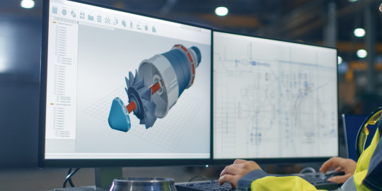
In the world of modern engineering and design, Computer-Aided Design (CAD) has revolutionized the way products are conceived, developed, and manufactured. As technology continues to advance, CAD automation emerges as a key player in enhancing design efficiency and fostering innovation. This blog post delves into the realm of CAD automation, exploring its significance, benefits, challenges, and potential future trends.
Understanding CAD Automation
CAD automation refers to the process of utilizing software tools and scripts to streamline various aspects of the design process. It involves automating repetitive tasks, generating complex designs, and facilitating seamless collaboration between designers and engineers. The goal of CAD automation is to reduce manual effort, minimize errors, improve consistency, and accelerate the overall design cycle.
Significance of CAD Automation
1. Efficiency Enhancement:
Automating routine and time-consuming tasks, such as dimensioning, detailing, and generating drawings, allows designers and engineers to allocate more time to creative and high-value tasks. This not only accelerates the design process but also increases productivity and reduces the risk of human errors.
2. Design Iteration and Optimization:
Automation tools enable rapid design iteration. Designers can easily generate variations of a concept, test different parameters, and evaluate multiple scenarios. This iterative process aids in identifying the most optimal design solution and fosters innovation.
3. Consistency and Standardization:
CAD automation enforces design standards and guidelines consistently across projects. This ensures that designs adhere to industry best practices and regulatory requirements, reducing the chances of errors caused by deviations from standards.
4. Complex Geometry and Customization:
Automated scripts and parametric modeling techniques enable the creation of intricate and complex geometries that might be challenging to achieve manually. Additionally, automation allows for easy customization of designs to meet specific customer requirements.
5. Collaboration and Communication:
CAD automation tools facilitate seamless collaboration between cross-functional teams. Design modifications, updates, and feedback can be efficiently communicated and integrated into the design process, enhancing teamwork and reducing communication gaps.
Benefits of CAD Automation
1. Time Savings:
Automating repetitive tasks drastically reduces the time required for design and drafting. This leads to faster project completion and quicker time-to-market for products.
2. Error Reduction:
Human errors are inevitable in manual tasks, but automation significantly reduces the risk. Consistent and standardized designs generated by automation tools mitigate the chances of costly mistakes.
3. Innovation Encouragement:
By handling routine tasks, designers can focus on exploring innovative design concepts and pushing boundaries. This results in more creative and inventive solutions.
4. Cost Efficiency:
Efficient design processes translate to cost savings. Reduced design time, fewer errors, and optimized designs contribute to lower production costs.
5. Enhanced Quality:
Automation tools ensure that designs adhere to defined standards, leading to higher-quality outputs that meet or exceed customer expectations.
Challenges of CAD Automation
While CAD automation offers numerous benefits, it's important to acknowledge the challenges that come with its implementation:
1. Initial Setup Complexity:
Developing and implementing automation scripts requires specialized skills and time. Setting up an automation workflow can be complex and resource-intensive.
2. Maintenance and Updates:
Automation workflows need continuous monitoring and updates to remain effective. Changes in design requirements or software updates may necessitate adjustments to the automation process.
3. Skill Requirements:
CAD automation demands a certain level of programming and scripting skills. Not all design professionals possess these skills, which might lead to a skill gap within the team.
4. Balancing Automation and Creativity:
While automation improves efficiency, there's a concern that excessive automation might stifle creativity. Striking the right balance is crucial to ensure that designers still have the freedom to innovate.
Future Trends in CAD Automation
The future of CAD automation holds exciting possibilities:
1. AI-Powered Design Generation:
Artificial Intelligence (AI) could play a significant role in generating design concepts based on user inputs and requirements. This could lead to the rapid creation of diverse design options.
2. Cloud-Based Collaboration:
Collaboration tools and CAD software are likely to move towards the cloud, enabling real-time collaboration between team members regardless of their geographical location.
3. Integration with Simulation and Analysis:
Automation could seamlessly integrate design with simulation and analysis tools, allowing for quicker evaluation of design performance and optimization.
4. Generative Design Evolution:
Generative design algorithms, driven by AI, could become more advanced, producing complex designs that consider multiple variables and constraints.
Conclusion
CAD automation is transforming the design landscape by freeing designers from repetitive tasks, empowering them to innovate, and enhancing design efficiency. While challenges exist, the benefits of CAD automation outweigh the drawbacks, and the continuous evolution of technology promises even greater possibilities in the future. Embracing CAD automation can position design teams at the forefront of innovation and efficiency in the rapidly evolving engineering and manufacturing industries.
ProtoTech Solutions' journey into the realm of CAD automation is a testament to the transformative power of technology. Their commitment to streamlining design processes, fostering innovation, and embracing the future sets an inspiring example for the entire design and engineering community. As ProtoTech Solutions continues to pioneer advancements in CAD automation, the design landscape stands poised for a future of unprecedented efficiency, creativity, and collaboration.
#CAD Automation#Design Efficiency#Design Workflow#Engineering Automation#Automation Solutions#Design Technology#AI-driven Design#Design Optimization#CAD Integration#Design Standards#CAD Software#CAD Customization
0 notes