#CAN bus transceivers
Explore tagged Tumblr posts
Visit Tumblr Blog
Explore Tumblr blogs with no restrictions, modern design and the best experience.
Last Seen Tumblr Blogs


Fun Fact
130K people were victims of a chain letter scam that affected Tumblr in May 2011.
Text
https://www.futureelectronics.com/p/semiconductors--comm-products--can/mcp2551-e-sn-microchip-8463747
High-Speed CAN Transceiver, CAN Transceiver, Ethernet controller
MCP2551 Series 5.5 V 1 Mb/s Surface Mount High-Speed CAN Transceiver - SOIC-8
#Comm Products#CAN#MCP2551E/SN#Microchip#High-Speed CAN Transceiver#CAN Transceiver#Ethernet controller#CAN bus transceivers#Ethernet MAC controller#Low Power CAN#industrial equipment#CAN protocol controller
1 note
·
View note
Text
IP-based solutions, CAN Bus Module, Can transceiver Module, CAN controller
UJA1163A Series 28 V 5 Mbps CAN System Basis Chip IC - HVSON-14
0 notes
Text
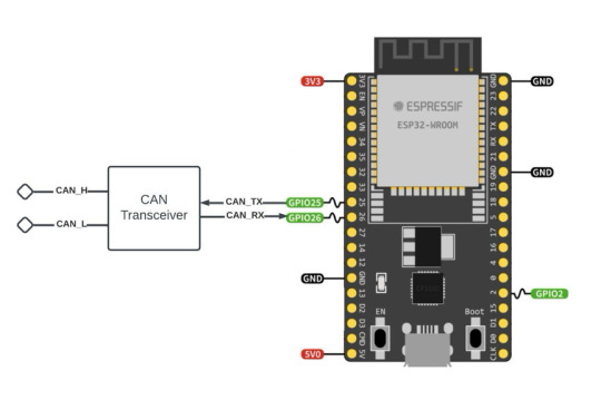
ESP32 Development Kits with Onboard CAN Bus Controller
The ESP32 includes a CAN Bus controller compatible with the NXP SJA1000, making it compliant with the CAN 2.0B (ISO 11898, also known as Classical CAN) specification.
Nevertheless, as with the SJA1000, the ESP32 CAN Bus controller only provides the data link layer and the physical layer signaling sublayer. As a result, an external transceiver module is needed to convert the ESP32's CAN-RX and CAN-TX signals into CAN_H and CAN_L bus signals.
#can bus#can fd#esp32#wroom-32#CAN Transceiver#Embedded System#Embedded Development#SJA1000#Classical CAN#Bluetooth#BLE#WiFi#IoT
1 note
·
View note
Text
https://www.futureelectronics.com/p/semiconductors--comm-products--i2c/pca9532pw-118-nxp-5033862
16-bit I2C-bus LED Dimmer, Embedded communication, image processing,
PCA9532 Series 5.5 V 350 uA 400kHz SMT 16-bit I2C-bus LED Dimmer - TSSOP-24
#NXP#PCA9532PW#118#Comm Products#I2C#16-bit I2C-bus LED Dimmer#Embedded communication#image processing#High-Speed#Isolated CAN Transceiver ICs#CAN bus lines#i2c modules#Can Power Systems#CAN transceiver#Ethernet MAC controller
1 note
·
View note
Text
https://www.futureelectronics.com/p/semiconductors--comm-products--can/mcp2551-i-sn-microchip-5584800
Can Power Systems, Ethernet controller, High-Speed CAN Transceiver
MCP2551 Series 5.5 V 1 Mb/s Surface Mount High-Speed CAN Transceiver - SOIC-8
#Microchip#MCP2551-I/SN#Comm Products#CAN#Power Systems#Ethernet controller#High-Speed CAN Transceiver#Ethernet MAC controller#CAN Controller Interface#Can bus communication#Controller Interface Module#Module Bus Drive
1 note
·
View note
Text
https://www.futureelectronics.com/p/semiconductors--comm-products--can/mcp2551t-i-sn-microchip-5971353
High-Speed CAN Transceiver, can transceiver circuit, Can Power Systems
MCP2551 Series 5.5 V 1 Mb/s Surface Mount High-Speed CAN Transceiver - SOIC-8
#Microchip#MCP2551T-I/SN#Comm Products#CAN#High-Speed CAN Transceiver#can transceiver circuit#Can Power Systems#Can controller#can bus#can bus voltage#Can bus voltage measurement#Embedded communication
1 note
·
View note
Text
https://www.futureelectronics.com/p/semiconductors--comm-products--i2c/pca9532pw-118-nxp-5033862
I2c bus, Embedded communication, Isolated CAN Transceiver ICs
PCA9532 Series 5.5 V 350 uA 400kHz SMT 16-bit I2C-bus LED Dimmer - TSSOP-24
#NXP#PCA9532PW#118#Comm Products#I2C#Ethernet MAC controller#communication protocol#i2c module#bus#Embedded communication#Isolated CAN Transceiver ICs#High-Speed CAN Transceiver#CAN transceiver#SPI bus#CAN bus lines
1 note
·
View note
Text
There's no getting away from it now, bucko. We have our killer pegged.

He could still be a co-conspirator, but unlikely. Servan was necessary for the bombing ploy, since he must have designed the bombs and the fancy transceiver. Especially if Icardi wasn't selling out to Amaterasu and this was, in fact, a Resistance leadership coup.
Which, at this time, seems the most plausible explanation. Even if it doesn't explain the minigame runaround.
But while Servan most certainly was involved, it's not clear what Margulaw would have even contributed if he had been complicit. There's nothing to suspect him of, and by extension no reason to suspect him.

Iruka is by far the most "not possible to be involved" out of the entire group. Completely out of the question.

And while I do think that Servan was involved in the bombing, he can't have made the jump. He also couldn't have shot Shachi from an equal height. Have you seen his stature? He's like three and a half feet tall.

My first thought had been that he's an Amaterasu fink, but at this point, I feel like that possibility can be eliminated. If he was working with the Peacekeepers to create an excuse for wiping out the Resistance, he could have left through the door and high fived his fellow cops on the way out.
Instead, he went for this elaborate escape mechanism so he could vanish from a district that's utterly saturated in jackboots. Fubuki and I had more than a few run-ins with them. So. No. He can't be in Amaterasu's pocket.
The other explanation is that he wanted control of the Resistance. He was spinning a narrative. "Unfit leader Shachi launched a terrorist threat against Kanai Ward and tried to murder civilians. Peacekeepers swarmed his hideout and cornered him. With no way out, he took his own life. I, Icardi, will better lead our organization into a far more prosperous future!"
This was a coup.
That could explain the minigame runaround too. To make his coup work, he needed only a terror threat, not a full-scale terror attack. He needed the first bomb to detonate in order to disguise the sabotage at the power plant. After that, easily disarmed bombs in fairly out-of-the-way locations with a supremely generous time limit would ensure that nobody was seriously harmed.
Icardi may have disagreed with Shachi's leadership, but I don't think he was a polar-opposite bomb-chucking anarchist stereotype.

A distraction. It's the smoke disguising Icardi's coup, creating a reason for Peacekeepers to raid the Resistance HQ.


That's also why Servan phoned in an anonymous tip to CTU. They wanted everyone to know that Yuma Kokohead is launching terror attacks against the city, in the name of the Resistance.

Sabotaging the power plant in order to create the escape channel they'd need, following their coup, of course. While Servan was manipulating Yuma and phoning tips to CTU, Icardi had to be on-site at the power plant to set the drainage bomb as well as to sabotage the valve handle and keep the water flowing.

Oh, we're moving towards the final confrontation? Huh.
Maybe Servan is innocent? That seems unlikely. He designed the camera-bombs and the transceiver-disarming device, and has a noted history of being a bomb specialist. Then he gave Yuma the transceiver signal that would arm the bombs and set everything in motion.
It's hard to imagine that he's unrelated to these events.

What. Talk fast, man, 'cause that's gonna be a hard fucking sell.


Yeah, I'm gonna stop you right there because that's not what you did. You didn't make it look like Peacekeepers shot him. You made it look like he shot himself, in a fit of ideological despair. You're spinning bullshit right now and I'm not buying it.

Also that. But he might have assumed an evacuation of Marunomon would have prevented anyone from being hurt. There was enough time, while it was taking place, for two separate alerts in the form of printed-out paper documentation to be distributed among power plant staff, so it's not like a huge wave of water buried the district in seconds. The flooding happened gradually.
In order to be effective, an act of protest must be disruptive. I could see Shachi believing that flooding the economic district would be a massively disruptive demonstration against Our Capitalist Overlords with low risk of harm to human life.
Problem is, Icardi's claim of "I made it look like the Peacekeepers did it" doesn't hold water.

...hang on, what? Yuma, where are you going with this?


Oh my god, it was a bank robbery.
I was fucking joking when I proposed that. WHAT. WHY. WHAT.
...why would he even need to kill Shachi to make that happen? How could that possibly contribute to pilfering safes from Marunomon? What the actual fuck?
Once he already had Yuma running around town disarming bombs and CTU chasing down Yuma as well as rooting out the Resistance in Dohya, he could just. Like. Go to the Power Plant and do the thing. Shachi's death is completely unnecessary. This makes no sense.


Apparently Servan was totally uninvolved somehow despite clear reasons to suspect his involvement! It was you and only you! The world's dumbest overcomplicating bank robber who got caught because he tacked on a pointless murder for shits and giggles!
14 notes
·
View notes
Text
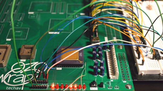
Wrap030-ATX First Tests
The best place to start with assembling and testing a board like this is the power supply. If there's a catastrophic error, like a direct short between supply rails, it's best to find out before wasting other components. Thankfully on this project, I'm using a standard PC power supply so all I need is some basic filtering capacitors. Not much to screw up there except maybe some backwards electrolytics.
Next is generally reset and CPU clock. These are essential for getting the CPU up and running and should be confirmed operational before continuing. Here again I'm using stock modular components — a brownout reset signal generator and a can oscillator — so debugging was minimal.
Finally, the CPU should be tested with these signals to see if it will free run (tie the CPU data bus to a known value, usually something like 0b00000000, and watching to see if the address bus increments freely).

The CPU free run test is an important one. It confirms the most basic functions of the board and the CPU are functional. A board that can't free run at this stage likely has some significant problem that must be solved before anything else will work.
Luckily, it passed this test!
I used the data bus transceiver sockets to attach test wires to, so I could tie all the data bus signals low. On the 68k architecture, $0000,0000 corresponds to the instruction ORI.b #0,D0 which is a 16-bit opcode ($0000) for an OR instruction followed by an immediate constant word ($0000). So for every 32-bit bus access, the CPU is fetching one complete instruction, incrementing the Program Counter by 4, then repeating. The result of the instruction is stored in the D0 register, so nothing is ever written to the bus.
This behaviour can be confirmed with a logic analyzer, but it's easiest to visualize by connecting LEDs to some of the higher address bits and watching them count up in binary (which is what I did here).
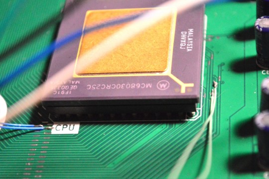
On the 68030 there is a bit more to do than just grounding the data bus. In particular, the CPU's asynchronous bus expects peripherals to report they are ready and have placed valid data on the bus by asserting the Data Strobe Acknowledge signals (DSACKn#). In normal operation, the system will delay asserting these signals to give the peripheral device enough time to do its job, signalling the CPU to insert wait states until the data is ready. For free run though, these signals can be tied low to signal to the CPU that the data it's requesting (all 0s) is ready immediately (because the data bus is tied to ground).
Here is where a last-minute addition to my PCB layout really came in handy. I removed the solder mask on these small sections of important signal traces so I would have a clear place to probe these signals on the top of the board. This also gave me just enough room to solder some 30 gauge wire to the DSACKn# and address signals for running the free run test.
Now that I know the most basic functions of the board are working, I can move on to the next step — running first code. To run real code I'll need ROM working, which will also require the bus controller CPLD to be minimally functional.
I am hoping to have this project at least running BASIC in time to exhibit it at VCF Southwest in Dallas at the end of June this year. I've got a lot of work still to do to reach that goal, but passing these first tests does give me hope that there are no huge show-stopping problems with my PCB (at least nothing that can't be worked around with a bodge wire or two)
#homebrew computing#vintage computing#wrap030 atx#motorola#mc68030#motorola 68k#motorola 68030#vcf southwest#VCFSW
13 notes
·
View notes
Text
Explore CAN Bus Testing and Design by Servotech
In the ever-evolving world of automotive and industrial electronics, Controller Area Network (CAN) Bus systems have become the backbone of modern communication between microcontrollers and devices. One company standing at the forefront of this technology is Servotech, offering state-of-the-art solutions in CAN Bus testing and design. This article dives deep into the essentials of CAN Bus systems and how Servotech is revolutionizing their development and verification through innovative tools and services.
What is CAN Bus?
CAN Bus (Controller Area Network) is a robust vehicle bus standard designed to allow microcontrollers and devices to communicate with each other without a host computer. Originally developed by Bosch in the 1980s for automotive applications, the CAN protocol has since become a staple in a wide range of industries including manufacturing, aerospace, and medical equipment.
The key strengths of CAN Bus include:
High-speed communication (up to 1 Mbps in CAN 2.0 and higher in CAN FD)
Error detection mechanisms
Multi-master capabilities
Reduced wiring complexity
Given its critical role in embedded systems, the design and testing of CAN Bus networks must be precise, reliable, and future-proof.
Why CAN Bus Testing is Critical
Modern electronic control units (ECUs) rely heavily on flawless communication to ensure vehicle safety, efficiency, and performance. Faults in a CAN network can lead to system malfunctions or complete breakdowns. Therefore, rigorous testing is crucial during development and after deployment.
CAN Bus testing addresses:
Bus integrity and performance
Error handling and fault tolerance
Signal timing and voltage levels
Protocol compliance
Ensuring these aspects allows manufacturers to detect and rectify errors early in the development cycle, reducing cost and time to market.
Servotech: Innovating CAN Bus Testing and Design
Servotech has established itself as a trusted partner for embedded developers and OEMs worldwide. Their comprehensive suite of tools and services for CAN Bus testing and design reflects a deep understanding of real-world engineering challenges. By combining hardware, software, and expert consultancy, Servotech offers an end-to-end solution.
Key Offerings by Servotech
1. Advanced CAN Analyzers
Servotech offers high-performance CAN Bus analyzers capable of real-time data monitoring, message filtering, error detection, and traffic logging. These tools are essential for developers during both prototyping and validation phases.
Features include:
Support for CAN 2.0 and CAN FD
Real-time data visualization and filtering
Automatic baud rate detection
Customizable script-based test automation
These analyzers streamline testing and help identify protocol violations and electrical issues early on.
2. Protocol Simulation Tools
Servotech’s CAN simulation software allows developers to simulate ECUs and test network responses in a controlled environment. This is especially useful for:
Regression testing
Fault injection
Load testing
Simulation accelerates development timelines by reducing the dependence on hardware availability.
3. CAN Bus Design Consultancy
Beyond tools, Servotech provides expert consultancy in the design of robust CAN Bus networks. Their team assists clients in:
Selecting appropriate transceivers and microcontrollers
Designing network topology for optimal performance
Ensuring EMC/EMI compliance
Creating scalable and modular architectures
This holistic approach minimizes design flaws and ensures a reliable system foundation.
4. Training and Workshops
Understanding the intricacies of CAN Bus is key to effective implementation. Servotech offers tailored training programs and workshops for engineering teams, covering topics such as:
CAN fundamentals and protocol layers
Troubleshooting and diagnostics
Design best practices
Use of Servotech tools for efficient testing
These sessions are available both online and on-site, enhancing team capability and project efficiency.
Servotech’s Competitive Edge
Several aspects make Servotech a leader in CAN Bus solutions:
a) Industry Experience
With years of experience across automotive, industrial automation, and IoT domains, Servotech understands the nuanced requirements of each sector and tailors its offerings accordingly.
b) Customization Capabilities
Servotech’s hardware and software tools can be customized to align with specific customer needs, including integration into existing test environments or support for proprietary protocols.
c) Compliance and Standards
All Servotech solutions are developed to comply with international standards such as ISO 11898, ensuring interoperability and future-readiness.
d) Seamless Integration
Servotech tools are designed to integrate smoothly with third-party platforms and diagnostic tools, facilitating a unified testing ecosystem.
Real-World Applications of Servotech CAN Bus Solutions
Servotech’s CAN Bus testing and design solutions are used in various applications, including:
Automotive
ECU development and validation
ADAS and infotainment systems testing
Electric vehicle communication networks
Industrial Automation
Factory machinery communication
Sensor-actuator coordination
Predictive maintenance systems
Medical Devices
Modular diagnostic equipment
Communication between control units in patient monitoring systems
In all these domains, reliability, speed, and precision are paramount—qualities Servotech consistently delivers.
Future Trends in CAN Bus and Servotech’s Vision
As the world moves towards connected vehicles, autonomous driving, and Industry 4.0, the demands on CAN Bus systems are increasing. Trends such as CAN FD, CAN XL, and Ethernet-based alternatives are pushing the boundaries of bandwidth and real-time performance.
Servotech is actively investing in:
Next-generation testing tools for CAN FD and CAN XL
AI-driven analytics for fault prediction
Cloud-integrated platforms for remote diagnostics
These innovations will ensure that Servotech remains a step ahead in enabling the smart, connected systems of tomorrow.
Conclusion
The reliability of embedded systems hinges on the seamless performance of communication networks like CAN Bus. Servotech’s comprehensive CAN Bus testing and design services empower engineers to build smarter, safer, and more efficient systems. With cutting-edge tools, deep domain knowledge, and a commitment to innovation, Servotech is a preferred partner for companies looking to excel in embedded communication technologies.
0 notes
Text
Intel Quartus Prime Pro Edition 25.1 Optimized for Agilex 3

Altera Launches Quartus Prime Pro Edition 25.1 for Agilex 3 FPGAs
Now available is Quartus Prime Pro 25.1, which supports Agilex 3, the latest Agilex release. Developers may design high-performing, power-efficient edge and embedded programs with this update.
Comprehensive Agilex 3 FPGA support
Agilex 3 FPGA family offers cost optimisation, high performance, and power efficiency for edge and embedded applications. This version lets you develop, test, and implement solutions faster with Agilex 3 higher-speed transceivers, on-chip dual Cortex-A55 ARM CPUs, and increased memory support, including LPDDR4.
For small board space applications, Agilex 3 uses Intel's variable pitch BGA packaging to design more efficiently and compactly. With this technology, developers can maintain performance and power efficiency while adding functionality to smaller spaces.
Security is essential for FPGA applications to protect sensitive data and IP. Agilex 3's physical security, authentication, and encryption capabilities strengthen designs' manipulation and assault resistance.
Nios V Soft Processor Enhancements
Nios V is vital for embedded applications and improves efficiency and performance. These improvements allow developers to make smaller, more efficient embedded devices.
Improved Nios V/g Core Performance Improved work completion and overall performance.
Nios V/c Core Area reduction saves 8% space, leading in smaller designs.
The Ashling RISCFree IDE's Visual Studio Code plugin simplifies Nios V software development.
TinyML Example Design with Nios V Application Note lets developers add machine learning (ML) to FPGA designs utilising microcontrollers.
Features of Embed Software
FPGA-based embedded applications need strong OS and virtualisation support. By adding Linux, RTOS, and hypervisor support, Quartus Prime Pro 25.1 lets developers build scalable, real-time, and virtualised embedded systems.
Linux Hardware Reference Designs Regular and standard editions for Linux development.
To support Xen, developers can virtualise FPGA programs.
RTOS supports Zephyr and Bare Metal, and FreeRTOS will arrive in Q2 (May).
Installer Improvements: Faster, flexible configuration
FPGA software should install and adapt easily. Quartus Prime Pro 25.1 improves installation with parallel processing, configurable component selection, and file management.
Installation in Parallel speeds up setup by installing many components simultaneously.
By letting users choose just the bits they need, Dynamic Components decrease installation time and disc space.
Troubleshoot hardware quickly with streaming debugging
Effective debugging reduces development cycles. The Streaming Debug IP for Signal Tap helps engineers debug FPGA designs by capturing real-time, high-bandwidth data.
Hardware debugging streaming allows real-time data flow for analysis.
Configurable streaming via STP Signal Tap Logic Analyser configures streaming and selects a debug host.
Simulation Enhancements
Quartus Prime Pro 25.1 improves integration, long-term support, and simulation with new native Altera AXI4 Bus Functional Models (BFMs).
Optimised for Quartus simulation workflows, native Altera AXI4 BFMs increase performance and compatibility.
Smooth Change With better toolchain integration, customers may switch to Altera AXI4 BFMs without substantial modifications.
Quartus Prime Pro 25.1 improves simulation performance, notably for transceiver protocol IP, enabling faster debugging and verification.
Better Transceiver Protocol IP simulation enhances PCIe, Ethernet, Serial Lite, JESD, and other transceiver protocols.
25.1 Beta Models The new simulation models for this edition focus on Ethernet and PCIe and are under beta testing.
Improved Efficiency Usually, 50% or more improvements speed up verification and reduce simulation time.
These simulation additions improve Quartus Prime Pro 25.1's transceiver-based FPGA design capabilities by speeding up simulations and reducing verification time.
Extra Quartus Prime Pro 25.1 Updates
QPDS Standard & Pro Containerised Images Docker Hub offers Quartus Prime Standard and Pro Editions containerised, simplifying deployment and improving cloud and CI/CD compatibility.
Separating timed closure data from Design Assistant results simplifies failure classification in Summary of Design Closure.
SDC Relative File Paths improve portability and script management for Synopsys Design Constraints (SDC) reports.
MTBF improvements It lets users adjust instance toggling rates to improve MTBF when default toggle rates are not suitable.
Static timing analysis improvements in Quartus Prime Pro 25.1 speed up timing problem identification and resolution.
Synthesis supports basic Quad-Port RAM. Automatic quad-port RAM inference expands memory design flexibility.
Complete Support for Byte Enable Inference in Synthesis: This adds 8-bit byte enables and supports 5, 8, 9, and 10-bit combinations, matching hardware capabilities.
Correcter Management Users can now write individual bytes within a word using the byte enable control signal to increase memory access and performance.
Better RAM inference lets designers use FPGA memory more readily.
FPGA AI Suite: Improved Usability and AI
As AI advances, FPGA-based inference systems must be more flexible and effective. This release includes better performance estimation, model support, and Agilex FPGA integration.
Support Agilex 3 Beta FPGA AI Suite beta supports Agilex 3 FPGAs. Build in Quartus with Agilex 3 and generate Inference IP targeting Agilex 5 in the architectural configuration file.
The RPM and DEB packages are now called “altera-fpga-ai-suite-” and the AI Suite is installed in “/opt/altera” instead of “/opt/intel”.
YoloV7 Model Support enables high-accuracy object recognition in robotics, surveillance, and industrial quality control.
Agilex 5 FPGA E-Series Example Design Support New Agilex 5 FPGA E-Series 065B Modular Development Kit sample designs are available.
This SoC example uses an ARM host CPU for AI inference. AI Inference IP and a novel layout transform enable folding and run-time configurability to improve AI model performance and usability.
Example of Hostless JTAG-Attach Design A system console linked to the Inference IP via JTAG allows users to setup and control IP functionality step-by-step.
Performance Estimator Uses Memory Bandwidth Users may now define external memory bandwidth when designing for memory-limited devices like Agilex 5 and Agilex 3, improving accuracy.
OpenVINO 2024.6 Integration FPGA AI Suite 25.1 uses the latest OpenVINO 2024.6 for stability and maintainability.
For two years, Quartus Prime Pro versions will only include the Long-Term Support AI Suite, which uses new optimisations and performance improvements.
FPGA AI Suite 25.1 simplifies FPGA AI inference with faster performance, more example designs, and greater model support.
Quartus Prime Pro 25.1 IP Features
After adding Agilex 3 IP cores and upgrading Agilex 5, Quartus Prime Pro 25.1 delivers real-time data processing, flexible memory access, and rapid connectivity for many applications.
Agilex 3 IPs
Agilex 3 has a wide range of memory, processor, and connectivity IPs for low-cost applications:
1.25 Gbps LVDS and MIPI D-PHY high-voltage and fast adaptable I/O Assistance interfaces.
PCIe 3.0, 10GE Hard IP, and 12.5Gbps transceivers ensure high-bandwidth applications.
LPDDR4 provides cost-effective embedded memory up to 2133 Mbps.
HPS EMIF ensures tight ARM Cortex integration.
HD Image and Video Processing Our VVP package accelerates video and vision processing applications.
JESD204B for Synchronising Data Converters synchronises 12.5Gbps multi-channels accurately.
The Transceiver Toolkit for Advanced Debugging improved transceiver link testing and debugging.
Agilex 5 IP updates
Performance and flexibility enhancements to Agilex 5 series IP include:
PMA-Direct real-time adaptive reconfiguration of multiple configurations
PCIe 3.0/4.0 Multi-Channel DMA supports x2/x4 Root Port (RP) and Endpoint (EP) modes.
Agilex 5 D Series enabled 12.5 Gbps per serial channel in Interlaken for scalable data transport.
Transceiver Toolkit 17.16 Gbps JESD204B Advanced Debugging ensures rapid, accurate data flow.
Dual-Simplex Mode Protocol JESD204C expands high-speed ADC/DAC interface for more advanced signal processing.
O-RAN IP: Supports 15–240 KHz subcarrier frequencies and real-time spacing changes via control messages. Scalable and conserved digital power.
The Agilex 3 and Agilex 5 FPGAs are ideal for embedded, networking, and AI-driven applications due to their performance, efficiency, and adaptability.
Conclusion
Quartus Prime Pro 25.1 improves Agilex 3 support, debugging tools, AI acceleration, IP cores, and usability. Optimisation for embedded apps, high-speed interfaces, or AI workloads is faster, more efficient, and more flexible with this version.
#technology#technews#govindhtech#news#technologynews#Quartus Prime Pro#Agilex 3 FPGAs#Agilex 3#Agilex 5#Agilex 5 FPGAs#Quartus Prime Pro Edition 25.1#Quartus Prime Pro Edition
0 notes
Text
Ethernet MAC Controller, I2C-bus Repeater, Ethernet Controller
MCP2551 Series 5.5 V 1 Mb/s Surface Mount High-Speed CAN Transceiver - SOIC-8
0 notes
Text
Mastering CAN Bus Testing and Design for Reliability
Introduction
Controller Area Network (CAN) Bus technology is a critical communication protocol used in automotive, industrial automation, and embedded systems. Ensuring the reliability of CAN Bus systems requires meticulous design and rigorous testing. This article delves into the principles of CAN Bus testing and design, the importance of testing, and best practices to achieve a robust and error-free network.
Understanding CAN Bus Communication
CAN Bus is a multi-master, serial communication protocol that allows microcontrollers and devices to communicate without a host computer. It is widely used in applications requiring real-time data exchange, such as vehicles, medical equipment, and industrial automation.
Key Features of CAN Bus
Fault Tolerance: Ensures communication even in the presence of errors.
High Speed and Efficiency: Supports data rates up to 1 Mbps.
Priority-Based Messaging: Assigns message priorities to avoid collisions.
Error Detection and Correction: Uses cyclic redundancy check (CRC) for data integrity.
CAN Bus Design Considerations
Designing a reliable CAN Bus system involves several crucial factors:
1. Network Topology
A well-structured topology minimizes signal reflections and interference. Common configurations include:
Linear Bus: Simple and commonly used for automotive applications.
Star Topology: Used in industrial automation but requires signal repeaters.
Hybrid Topology: Combines multiple topologies for flexibility.
2. Termination Resistors
Proper termination is essential to prevent signal reflections. A standard 120-ohm resistor is placed at both ends of the bus.
3. Cable Selection
Twisted Pair Cables: Reduce electromagnetic interference (EMI).
Shielded Cables: Protect against external noise in industrial environments.
4. Node Design
Each node should include transceivers, controllers, and proper grounding to ensure stable communication.
Importance of CAN Bus Testing
Thorough testing is essential to validate performance, detect faults, and ensure compliance with industry standards. CAN Bus testing involves different methodologies:
1. Electrical Testing
Measures voltage levels, signal integrity, and resistance.
Identifies power fluctuations that may affect performance.
2. Protocol Testing
Validates message timing, arbitration, and data integrity.
Ensures compliance with CAN 2.0, CAN FD, and higher-layer protocols like ISO 11898.
3. Error Testing
Detects bit errors, frame errors, and acknowledgement failures.
Simulates fault conditions to evaluate system robustness.
4. Performance Testing
Analyzes bus load, response times, and latency.
Helps optimize network efficiency and reduce bottlenecks.
Tools for CAN Bus Testing
Several specialized tools help engineers diagnose and troubleshoot CAN Bus networks effectively:
1. Oscilloscopes
Capture and analyze CAN signals.
Detect signal noise and timing issues.
2. Protocol Analyzers
Decode CAN messages in real time.
Provide detailed insights into data transmission.
3. Network Simulators
Simulate various network conditions for testing under different scenarios.
Validate system behavior before deployment.
4. CAN Bus Testers
Detect and diagnose faults quickly.
Offer automated testing capabilities.
Best Practices for CAN Bus Reliability
Ensuring a stable and efficient CAN Bus system involves adhering to best practices:
1. Proper Termination
Use the correct 120-ohm termination resistors at both ends.
Avoid unnecessary stubs that can cause reflections.
2. Minimizing Noise and Interference
Use twisted-pair and shielded cables.
Keep power and data lines separate to reduce EMI.
3. Regular System Monitoring
Implement logging and monitoring tools.
Analyze trends to predict failures before they occur.
4. Comprehensive Testing Strategy
Combine electrical, protocol, and error testing.
Perform stress tests to evaluate network resilience.
5. Compliance with Industry Standards
Adhere to ISO 11898 and other relevant standards.
Ensure compatibility with existing CAN Bus implementations.
Conclusion
Mastering CAN Bus testing and design is essential for achieving a reliable communication network in critical applications. By following best practices, using the right tools, and performing rigorous testing, engineers can enhance system efficiency and reduce the risk of failures. A well-structured CAN Bus network leads to improved performance, increased safety, and long-term stability in demanding environments.
0 notes
Text

Embedded CAN Bus Development with the ESP32 Processor
The ESP32 is a versatile microcontroller featuring dual-core processing, Wi-Fi, and Bluetooth capabilities. One of its lesser-known features is the integrated SJA1000-compatible CAN controller. When paired with an external CAN transceiver, such as the MCP2551 or TJA1050, the ESP32 can interface seamlessly with CAN networks.
1 note
·
View note
Text

Buy CP2102 USB to TTL MODULE at Affordable Price in Ainow
CP2102 USB to TTL MODULE
This is the CP2102 USB to TTL module UART serial converter. This is a great little tool for embedded systems that require a serial connection to a computer. The board can simply attach to a USB bus and will appear as a standard COM port. This CP2102 USB to TTL Module doesn’t require any external oscillator, it onboard-board voltage regulator, and it even uses a reprogrammable internal EEPROM for the device description. The full hardware UART has flow control for baud rates from 300bps to 921600bps. This breakout also allows you to connect the TX/RX pins of your favorite microcontroller or serial application to the RX/TX pins of the breakout, creating a simple serial cable replacement.
Supported operating systems:
Windows 98/Me/2000/7
MAC OS-9
MAC OS
X-Windows CE
Linux 2.40 or later
Features:
Brand new and high quality
Included USB transceiver, without external circuit device
Includes a clock circuit and power-on reset circuit
With 3.3V and 5V dual power output
With three LEDs: power indicator, data reception indicator, the data transmission indicator, working status
Meet the USB2.0 specification requirements
SUSPEND pin supports USB suspend state
With self-recovery fuse. In the event of the accidental short circuit, it can effectively protect your computer USB port and Downloader
With reset signal output, etc. directly to the Arduino board Promini download!
Asynchronous serial data bus compatible with all handshake and modulation controller interface signals
The supported data format is 8 data bits, 1 stop bit and parity bits
Connotation 512 byte receive buffer and 512 bytes transmit buffer
Supports hardware handshaking or X-ON/X-OFF
#arduino#electronic components#sales in chennai#raspberrypi#sensor#electronics components#robotic kits#adxl335 module price
1 note
·
View note