#Can bus voltage measurement
Explore tagged Tumblr posts
Visit Tumblr Blog
Explore Tumblr blogs with no restrictions, modern design and the best experience.
Last Seen Tumblr Blogs


Fun Fact
Tumblr was the first site to host the blog for President Barack Obama in 2011.
Text
https://www.futureelectronics.com/p/semiconductors--comm-products--can/mcp2551t-i-sn-microchip-5971353
High-Speed CAN Transceiver, can transceiver circuit, Can Power Systems
MCP2551 Series 5.5 V 1 Mb/s Surface Mount High-Speed CAN Transceiver - SOIC-8
#Microchip#MCP2551T-I/SN#Comm Products#CAN#High-Speed CAN Transceiver#can transceiver circuit#Can Power Systems#Can controller#can bus#can bus voltage#Can bus voltage measurement#Embedded communication
1 note
·
View note
Text
Anyways, I wouldn't be worth listening to if I didn't give something more useful than idle complaining.
If you need to try and wipe an SSD as much as you can short of literally destroying it then here you go.
First, it has to be directly attached to the SATA or NVMe bus. Then use a utility from the manufacturer to issue the Secure Delete command.
Next, get some kind of linux running, any of the live boot ones is fine and it doesn't particularly matter. Run a dd command writing the entire drive with random nonsense from /dev/urandom. Pretty typical up to this point but from here we go a little wild.
Now we go back to that utility from the first step. Yes, we'll Secure Delete again just for good measure. More info here, SD supposedly simultaneously zaps every data cell to erase the disk. Since the cells can act like little capacitors and hang on to a bit of residual voltage, we do this twice to ensure that any stragglers after the random write will "look like" it only ever had a high bit stored in it.
And we're back in the live boot once again. And yes, we're doing a total disk write again. /dev/urandom so on and so forth. A little explaining, the desired outcome is that this will meddle a bit with side-channel snooping via the wear-leveling mechanism. It also just makes you feel better knowing you had two passes of random data which should make the NAND gates not hold enough coherent voltage to form the data it once had.
Staying in linux, once that's done we're gonna dd from /dev/zero. Where the last two disk fills were to jumble things up and possibly not entirely useful in all cases, this one ought to force the SSD's underlying controller to erase every block so it can write all these zeros. The reason for this instead of another Secure Delete is to try to flood out copies of data from the control and support circuitry. If we can't directly command it to discard every bit it might be holding then we'll try to wash it out instead.
We're getting there, I'm sorry but go put random data back on it. This will make sense in a second I swear. Because next we'll partition the disk and we want garbled nonsense on it before we do that.
After you've done that, and gotten a giant partition on it and a filesystem on it, it's time to write some more. Using some incantations on the terminal, fill the drive with files. It doesn't matter much if you use /dev/urandom or /dev/zero for the contents because we're targeting the TRIM system this time.
I know you'll hate me for this next one but now you gotta delete all those files. If you thought ahead, you probably made them sizeable to make this faster.
Now it's time for coffee and a smoke; while it deletes shit and TRIM does it's thing you'll wanna let it sit for an hour or so. Then one last visit to Secure Delete and you're done.
This procedure sounds, feels, and likely is complete overkill but this is the best I got. I will warn you that you'll have lower performance for a while probably and it will certainly reduce the lifetime of the SSD.
If at all possible do just enough to do the job. If you are not worried about someone frankensteining your data, selling the SSD or giving it to family as a hand me down then the first two steps are likely enough. If you're putting it on eBay or you feel your threat level is higher than normal, going to the end of Step 4 or Step 5 ought to be enough. If you somehow have the nuclear codes or are particularly frightened about your data security, or are reusing the SSD for encrypted data then I'd go through to the end.
I cannot stress enough that this is extremely brutal on the SSD. They aren't really meant to be securely wiped. You should assess what data you intend on putting on them before ever using it to know if you need to use encryption of whatever degree or perhaps use a magnetic disk (with encryption too if you can!) instead if speed is not a concern. HDDs are far easier and confirmed to be capable of complete wiping with no way to skim data.
Also a disclaimer, I am not the owner of vast tech resources so I can't really test how effective this truly is because broke. I also shake too much now to hot air chips off anyways. If you are inclined, I suppose you could try to get a data recovery place to see if they can get any data once you're done just for curiosity.
#a much longer post than usual but you can't shortform this stuff#also rip to low-tech peeps you'll have to ask your weirdo linux cousin for a favor and hope they help#again this is fucking brutal on the SSD#eight full disk cycles is borderline abuse but gotta crack a few eggs#so like don't do this if your SSD is pushing highschool if you need to keep using it
2 notes
·
View notes
Text
Battery Management System (BMS) For Lithium Battery Pack
Olelon Energy’s In-House Developed LiFePO4 Battery Management System (BMS)
BMS (Battery Management System) is a crucial component of lithium batteries. The primary functions of a BMS are to monitor and control various parameters of the battery to ensure its safety, reliability, and lifespan. Specifically, the functions of a BMS include:
Battery Monitoring: Real-time monitoring of each battery cell’s voltage, current, and temperature.
Battery Protection: Take immediate action to protect the battery from overcharging, over-discharging, excessive current, and abnormal temperatures to prevent damage.
Energy Management: Calculating and displaying the remaining battery capacity and available time, ensuring users are aware of the battery status.
Balanced Charging: During the charging process, the BMS ensures that each battery cell reaches the same voltage through a balancing circuit, thereby extending the battery pack’s lifespan.
Fault Diagnosis: Real-time detection of the battery pack’s operational status and providing diagnostic information in case of faults.

Benefits for Batteries
Extended Lifespan: Effectively managing the charging and discharging process and temperature of the battery prevents overcharging, over-discharging, and overheating, thereby extending the battery’s lifespan.
Increased Safety: Monitoring the battery status and promptly addressing abnormal situations to prevent incidents like fires and explosions.
Optimized Performance: Ensuring each battery cell in the pack operates at optimal conditions through balanced charging and energy management, enhancing overall performance.
Reduced Maintenance Costs: Real-time monitoring and fault diagnosis allow users to understand the battery status and take preventive measures, reducing maintenance and replacement costs.
A Battery Management System (BMS) typically consists of the following main components:
Battery Monitoring Unit (BMU):
Function: Monitors the voltage, temperature, and current of each battery cell.
Components: Voltage sensors, temperature sensors, current sensors.

Main Control Unit (MCU):
Function: Collects and processes data from the BMU, executes battery management algorithms, and controls the charging and discharging of the battery.
Components: Microprocessor or microcontroller, memory, communication interfaces.
Communication Module:
Function: Facilitates data transmission between the battery and external devices (such as the vehicle’s onboard computer and charger).
Components: CAN bus, UART, SPI, and other communication interfaces.
Protection Circuit:
Function: Disconnects the battery from external circuits in the event of anomalies (such as overcharging, over-discharging, overcurrent, or overheating) to protect the battery.
Components: Relays, fuses, circuit breakers.
Balancing Circuit:
Function: Ensures that each battery cell reaches the same voltage during charging, thereby extending the battery pack’s lifespan.
Components: Active balancing circuits or passive balancing circuits.
Thermal Management System:
Function: Manages the temperature of the battery to prevent overheating or overcooling.
Components: Fans, heat sinks, heaters, cooling fluids, etc.
Software Component:
Function: Implements battery management algorithms, provides a user interface, and monitors battery status.
Components: Firmware (embedded software), application software (such as battery management software).
Olelon Energy’s In-house Developed BMS
All of Olelon Energy’s lithium battery products come equipped with in-house developed BMS systems. Olelon has extensive R&D experience and strong capabilities, ensuring that its BMS systems are at the forefront of the industry in terms of functionality and performance. Specific advantages include:
High Reliability: The in-house developed BMS system undergoes rigorous testing and validation, ensuring high reliability and stability.
Intelligent Management: Utilizing advanced algorithms and intelligent control technologies to achieve precise management and control of the battery.
Strong Compatibility: The in-house developed BMS system can flexibly adapt to different models and specifications of battery packs, meeting various application needs.
User-Friendly: Providing detailed battery status information and fault diagnostic reports to help users better manage and maintain their batteries.
Olelon Energy’s lithium batteries not only provide high-performance and long-lasting battery products but also benefit from professional BMS protection, significantly enhancing safety and cost-effectiveness. We highly recommend purchasing Olelon Energy’s lithium batteries to experience top-notch battery management technology and superior product quality.
It should be noted that when a BMS sends a request, it needs to allow sufficient response time for subsequent processing intelligence. More importantly, the current overcurrent protection strategy for the BMS must be coordinated with the vehicle controller and the load intelligent controller. Discordant strategies produce the unpleasant phenomenon in which strategies work well but often fail.
This is one of the significant advantages of Olelon Energy’s in-house developed BMS. Their custom-developed BMS can tailor solutions to address these issues effectively.
#BMS#GOLF CART BATTERY BMS#EV BMS#GOLF CART LITHIUM#CLUB CAR BMS#EZGO BATTERY BMS#BATTERY MANAGENET SYSTEM
0 notes
Text

GF1115P PROGRAMMABLE AC LOAD UNIT
GF1115P three phase programmable AC load unit is mainly used as the load for on-site verification of electric vehicle AC charging pile. The on-site detection process of AC charging pile can be realized by cooperating with our GF1115 AC charging pile on-site test set. The whole detection process meets the requirements of relevant national detection standards and measurement standards JJG 1148-2018 verification regulation of electric vehicle AC charging pile. The internal motherboard of the resistance load box adopts the processor chip of armcortex-m4 core architecture, which automates the workflow of the whole resistance load box, reduces manual participation and saves operation time. The internal structure adopts multi-channel high-power resistance parallel connection, which is connected through high-quality relay control. Multiple gear switching can be realized through the control relay. The whole process is fully automated without manual participation. Forced air cooling is adopted, and the circuit structure is simple without too much maintenance, saving the heat dissipation cost. Internal temperature detection is set to monitor the working temperature in the box in real time, ensuring the safety and reliability of the load in use. Two national standard AC charging gun sockets are installed on the box to facilitate user cascade and increase load power.
FEATURES ■ Forced air cooling; ■ Remote control via CAN bus or serial port; ■ With insulation grounding protection inspection function; ■ The load box has the function of automatic resistance shift; ■ The equipment can be powered supply by mains AC supply or charging pile; ■ It has the functions of emergency stop protection, overcurrent, overvoltage and short circuit protection; ■ Under the rated voltage, the minimum current step is 4.5mA, the minimum power step is 1W, and all have 8192 gears; ■ Realize the power verification points required in JJG 1148-2018 verification regulation for AC charging piles of electric vehicles; ■ Support a variety of working modes, constant current mode, constant voltage mode, constant resistance mode, constant power mode; ■ The box body is equipped with 2 metering sockets meeting the safety requirements, and the loads are controlled through CAN bus; ■ With advanced control algorithm and DSP digital control implementation, it is suitable for various load regulation requirements with high precision, high speed and high stability; ■ The equipment is equipped with voltage and current calibration and correction function, which can calibrate and correct the measured value of the instrument at any time, so as to ensure the measurement accuracy of the instrument used for a long time; ■ Built in temperature sensor, when the temperature in the box is too high, it will actively disconnect the load for high temperature protection, and send out an alarm at the same time. In addition, it can try to monitor the temperature in the box through the communication port;
APPLICATION ■ Electrical laboratory; ■ EV & Charging pile factory; ■ Metrological service center; ■ Laboratories of power utilities; ■ Third party testing organization; ■ Electricity power bureau & power company; ■ National Metrology and testing department; ■ Charging pile operation and maintenance organization;
1 note
·
View note
Text
How Much Current Voltage Can Your Enclosures Handle?
When selecting an industrial electrical enclosure, one of the most critical considerations is how much current and voltage the enclosure can handle. This factor directly impacts safety, performance, and compliance with electrical standards. Let’s break down what you need to know about voltage ratings and current capacity in electrical enclosures.

Understanding Voltage and Current Ratings
Voltage Rating: This refers to the maximum electrical potential an enclosure can safely handle without causing insulation failure or arcing. Enclosures typically have voltage ratings that align with common industrial standards, such as 600V for heavy-duty applications.
Current Rating: This measures the amount of electrical current (in amperes) the internal components, such as terminal blocks and bus bars, can safely carry. Higher current ratings are necessary for equipment handling substantial power loads.
Factors That Influence Electrical Ratings
Material Composition: Enclosures made from materials like fiberglass-reinforced polyester or polycarbonate offer excellent insulation, resisting high voltages and reducing the risk of electric shock.
Design and Construction: Well-sealed enclosures with robust gaskets and properly rated connectors enhance voltage handling by preventing moisture ingress and contamination.
Application Environment: Industrial environments can be harsh, with factors like humidity, chemicals, and temperature fluctuations affecting voltage endurance. NEMA or IP-rated enclosures ensure reliability in such conditions.
Ensuring Compliance and Safety
Consult Product Specifications: Always check the enclosure's datasheet for its maximum voltage and current ratings. Allied Moulded enclosures provide clear specifications based on industry standards.
Follow Electrical Codes: Adherence to codes such as the National Electric Code (NEC) ensures that enclosures are used within their intended electrical capacities.
Perform Regular Maintenance: Periodic inspections help maintain the integrity of electrical enclosures, preventing failures due to wear and environmental factors.
Why It Matters
Using enclosures with the correct voltage and current ratings prevents electrical hazards such as short circuits, equipment damage, and even fire risks. Properly rated enclosures ensure reliable and safe power distribution in industrial facilities.
Choosing the right enclosure for your industrial electrical system can seem complex, but understanding current and voltage ratings simplifies the process. Allied Moulded offers a range of high-performance enclosures designed to meet industrial demands while ensuring long-term safety and compliance.
Source Url: - https://khollott.com/how-much-current-voltage-can-your-enclosures-handle/
0 notes
Text
How to Build an Efficient Battery Management System (BMS)
When designing a monitor circuit for a new battery-powered system, optimizing cost and manufacturability is a critical task. The first step is to define the system’s preferred structure and the placement of the batteries and associated electronic components. Once the basic structure is clear, the next challenge is to make trade-offs in the circuit topology to optimize communication and interconnects.
Impact of Battery Size on Power System Design
The size of the battery directly affects the overall structure of the power system. Designers must decide whether to use many small batteries to fit into a complex battery module or battery pack, or whether to opt for larger batteries, which may be constrained by weight and size limitations. For example, in automotive design, batteries may be distributed across various spaces in the vehicle, maximizing space utilization if the battery is installed.
Interconnects Between Battery Management System and Testing Signals
An effective Battery Management System (BMS) needs to account not only for the battery itself but also for the interconnects between the battery, module, BMS, and the final application interface for testing and telemetry signals. In many cases, data acquisition circuits are integrated within the battery module or pack so that crucial information, such as production IDs, calibration data, and usage specifications, can be carried with replaceable components, minimizing the number of high-voltage rated wires in the wiring harness.
Battery Measurement Points and Hardware Topology Design
https://www.sunvoltbat.com/wp-content/uploads/2024/10/03-9.jpg
Remote Measurement and Data Transmission
In high-efficiency BMS, remote measurement circuits and the CAN bus protocol are used for internal communication between modules. This reduces the data transfer rate and mitigates electromagnetic interference (EMI) issues. The CAN bus protocol allows multiple small processors in the system to share computing tasks, improving overall system efficiency and reliability.
Temperature Management and Battery Capacity Balancing
Battery capacity balancing is crucial for BMS, especially for lithium-ion batteries. Imbalances can lead to heat management issues, affecting long-term performance. Designers need to consider the distribution of temperature probes to accurately correlate the battery’s charge state with voltage readings.
Efficient Battery Monitoring and Data Acquisition
For example, the LTC6803 battery pack monitor IC is an ideal core component for a BMS. This IC provides multi-channel data acquisition functionality, enabling effective voltage measurement of the batteries, along with auxiliary measurements for temperature, calibration signals, and load current.
Energy Efficiency and Cost-Effectiveness in Battery Management Systems
One important improvement in the LTC6803 is its ability to be powered directly by the battery pack, enhancing system efficiency and cost-effectiveness. By performing precise ADC measurements and optimizing battery current control, the LTC6803 reduces battery power consumption and prevents capacity imbalances caused by mismatched battery currents.
Conclusion
Designing a BMS involves many complex factors, especially those directly affecting system packaging and structure. After carefully considering mechanical designs, electronic circuits, and information flow, using scalable data acquisition solutions like the LTC6803 platform can significantly improve system performance and cost-efficiency.
0 notes
Text
BMS Safety Design: Best Practices for Preventing Battery Hazards

Voltage isolation and strong EMC anti-interference capabilities are prerequisites for BMS collection circuits. Special integrated circuits are generally not advised because they cannot achieve fault diagnosis, accuracy, passive equalization, or high-precision AD conversion. Examples of these circuits include optocoupler relay + external AD, data processing, passive equalization, drop monitoring, and high anti-interference ability. They are hard to guarantee, and they are not very resistant to interference.
It is advised that the voltage and temperature monitoring points be set to 1:1 and +2 (monitor module connector temperature), respectively, to guarantee that the temperature of each cell can be observed. Temperature monitoring points must also be installed on the battery pole to reduce the temperature monitoring delay and increase accuracy. Incorporate temperature monitoring at critical locations that are prone to overheating, like circuit breakers, relays, and power bus connection points.
Battery system safety will be directly impacted by SOS, and BMS ought to be able to assess the state of battery safety. It is impossible to determine the actual temperature inside the battery because temperature monitoring is either not done at this time or is limited to measuring the temperature of the confluence. As a result, there is a serious hidden risk to the battery’s safe operation when the heat inside the battery gets out of control and the rapidly rising temperature is not noticed in time.

Likewise, in the event that both the battery temperature and internal pressure rise too high, the safety valve will open. However, since safety valve monitoring is currently lacking, preventive actions such as shutting off the circuit, halting operation, initiating local cooling, and initiating firefighting cannot be taken in a timely manner. As a result, the two points mentioned above will eventually lead to breakthroughs in BMS security design.
Energy Storage BMS Development Trend
As monomer battery capacity increases, battery imbalance becomes more severe.
Passive equalization technology is no longer sufficient to balance battery systems and extend battery life.
Active equalization technology is an inevitable trend in the development of energy storage BMS.
Active equalization can extend battery life by 20%, which has high economic benefits.
Development Trend of Energy Storage BMS Battery Sensing Technology
The development of battery sensors and wireless BMS has become a priority due to the swift advancement of this technology. Future research and discussion on BMS are critically needed.

Problems with the technology of the current battery management system. There are obstacles in the way of technological advancement for the current battery management system:
1. There are two unsolvable issues because the voltage and temperature recorded by the current battery management system are the external parameters of the cell.
(a) Because the battery’s internal temperature cannot be measured, it is impossible to accurately determine how hot it gets inside. As a result, in the event of a small internal short circuit or thermal runaway cell, prompt safety warning and protection are not possible. This is a really big issue. The temperature inside the battery can be used to predict the thermal runaway of the battery in advance, preventing many combustion and explosion accidents that have happened in electric cars and energy storage power plants.
However, the system has experienced thermal runaway precisely as a result of the temperature gradient’s influence and the delay in temperature sampling. It’s too late to issue warnings and safeguards. This problem, which must be resolved immediately, is connected to the battery system’s safety.
(b) It is impossible to precisely determine the true state of the battery, including its capacity, health, attenuation, safety status, etc., since the real temperature and other state parameters inside the battery cannot be obtained.
2.The current battery management system must gather wire harness data to gather parameters like voltage, temperature, and other data. Numerous failure hazards, including poor contact, will arise because of the numerous geranium beams, sampling points, and connectors attached to the wire harness. In addition, it will result in production issues, insulation deterioration, and power leaks brought on by wire harness aging, damage, or extrusion. The system’s potential safety risk.
3. Since wire harness installation is typically done by hand, production and installation costs will inevitably rise.
4. Ineffective cell detection in the absence of installation and operation; damage to the battery; and thermal runaway safety.
Energy storage BMS development is moving in the direction of active equalization technology. This is because active equalization, particularly for large-capacity battery systems, can more successfully balance battery systems and increase battery life. Because active equalization technology can increase battery life by up to 20%, it offers significant economic benefits.
Since batteries account for a large portion of the cost of energy storage systems, this represents substantial savings for users of energy storage. Active equalization technology is where energy storage BMS development is trending. This trend is advantageous since it will result in energy storage systems that are more dependable and efficient.
#Battery Hazard Prevention#Battery Management System (BMS) Safety#Battery Safety Hazards#BMS Best Practices#BMS Safety Design
0 notes
Text
DAC0832 Digital-to-Analog Converter
Digital-to-analog converters (DACs) are often built into microcontrollers but tend to be slow, noisy, and lack resolution. So, we frequently use specialized DAC chips.
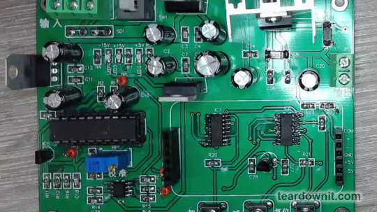
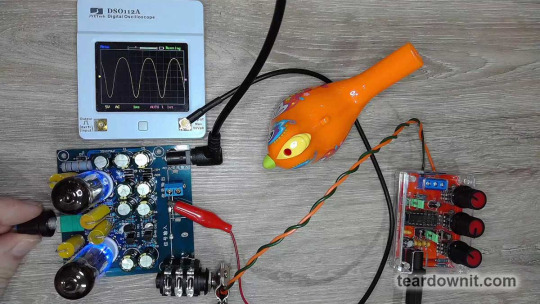
Today's example is a digitally controlled voltage regulator module that could be used in a lab power supply. The workhorse here is the LM317T chip, which has the DAC0832 digital-to-analog converter at its core.
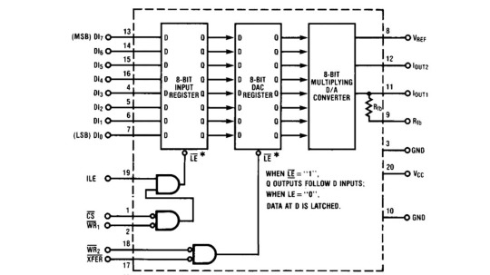
The DAC0832 is a pretty advanced chip, with not one but two latches arranged in sequence. This setup allows it to store digital data from the microprocessor bus and convert it to an analog value at just the right moment.
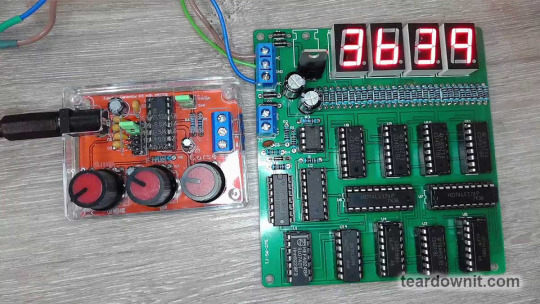
In the post about the 74HC374 latch, we used it to freeze the readings on seven-segment displays for a second while counting input pulses.
After a second, the data from the counters was sent out to the display decoders, showing the frequency of the input signal measured a second earlier. Meanwhile, the next count of pulses was happening. This made for a good frequency counter.
Each of the two latches in the DAC0832 can be made transparent, meaning asynchronous. In this mode, data from the input instantly appears in the output.
A logic high on the ¬LE (¬LATCH ENABLE) pin is needed to set the input latch to transparent asynchronous mode. You could call it LATCH DISABLE without the ¬ sign.
¬LE = ILE & (¬¬CS & ¬¬WR1) = ILE & ¬(¬CS | ¬WR1).
In simpler terms, you need a logic high on the ILE (INPUT LATCH ENABLE) input and a logic low on at least one of the two inputs, ¬CS (¬CHIP SELECT) or ¬WR1 (¬WRITE1). The ¬WRITE1 and ¬WRITE2 inputs are used for strobe signals.
For the 8-bit DAC latch register, the logic for ¬LATCH ENABLE is more straightforward:
¬LE = ¬¬XFER & ¬¬WR2 = ¬(¬XFER | ¬WR2).
So, you need a low logic level on at least one of the inputs: ¬XFER (¬TRANSFER) or ¬WR2 (¬WRITE2).
The heart of the DAC0832 is the analog-to-digital converter. This analog multiplexer switches precision silicon-chromium resistors deposited on a silicon chip.
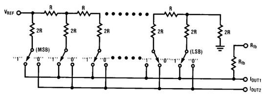
This manufacturing technique ensures high accuracy and temperature stability, which is why we use DAC chips in our favorite high-fidelity audio gear.
Plus, a multiplexer can work much faster than pulse-width modulation (PWM) analog-to-digital conversion, which we often use in Arduino DIY projects.
Also, PWM produces square pulses with different duty cycles with a broad frequency spectrum. The frequencies might be inaudible, but their interference with other frequencies in the device can create audible noises, which can be pretty unpleasant.
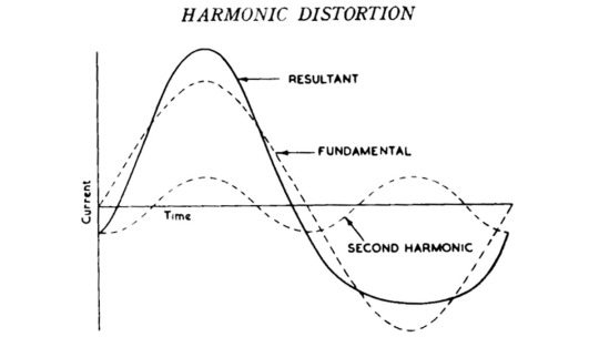
The homemade tube amplifier article mentioned that asymmetrical and softly clipped waveforms sound pleasant and musical to human ears because they're full of even harmonics.
But a square, symmetrical waveform has many odd harmonics, which aren't so nice to listen to, especially when they create dissonance with the overtones of other sounds played at the same time.
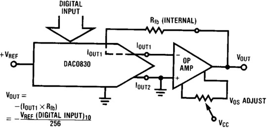
The DAC0832 needs an external operational amplifier to convert the current through switched precision resistors into an output voltage.
We'd probably go with the NE5532 for audio output, which we used for a simple, affordable, and high-quality headphone amp.

But the good old LM358 will do fine for a power supply. Here, op-amp IC4A converts the output current of the DAC0832 into voltage, and IC4B amplifies the resulting signal by six times.
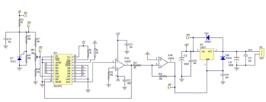
The TL431 chip generates the DAC0832's reference voltage, which is adjusted with the potentiometer RP1. The voltage ranges from 5×1100/1200=0.42V to 4.58V.
The output of IC4B is connected to the adjustment input of the LM317. Therefore, this chip's output voltage, and therefore our homemade power supply's, will be 1.25 volts higher than IC4B's.
So, the output voltage formula is:
Vout = 1.25 + 6 * Vref * DIGITAL INPUT / 256 = 1.25 + 0.024 * Vref * DIGITAL INPUT.
Adjusting the reference voltage can change the increment and decrement steps when pressing the corresponding buttons on the power supply's front panel.
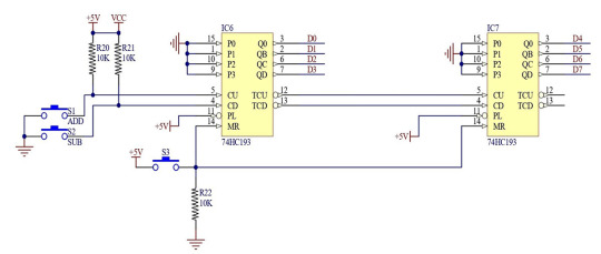
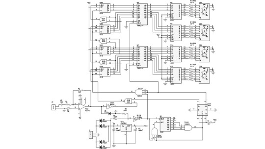
The digital value for converting to a voltage is set by two 74HC193 four-bit up/down counters.

These are presettable counters, similar to the ones we used as registers in our DIY 4-bit CPU.
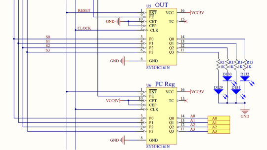
Each CPU's four registers used one SN74HC161L chip as a latch. The increment function was only used in the program counter (PC) register. The other three registers disabled it by grounding the CEP and CET control inputs.
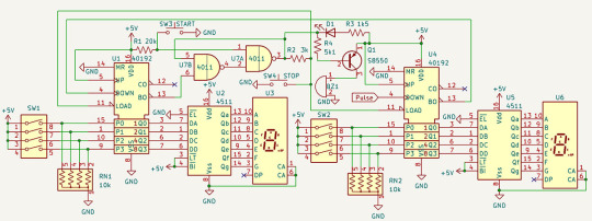
We used the decrement function in a countdown timer that could be set to any number of seconds from 0 to 99.

Thanks to the preset function, the chosen value from the PRESET ROM of our electronic traffic light tells the second counter how long the current signal combination should last. The decrement function was also used there.
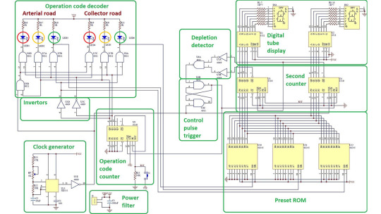
In today's power supply, we do not use the preset function but both increment and decrement counting. There's also a reset button to set both counters to zero.
Accordingly, the digital-to-analog converter will also be set to zero since both of its internal latches are permanently in transparent asynchronous mode.
To lock the chip in this mode, the ¬CS, ¬WR1, ¬WR2, and ¬XFER control inputs are soldered to ground.
We could make a power supply with non-volatile preset memory if we used a microcontroller instead of up/down counters. The microcontroller's analog-to-digital converter could be used for the voltmeter and ammeter.
And if the microcontroller doesn't have enough pins to connect the 8-bit DAC data bus, we could use a shift register for serial data transfer.
In this case, the DAC0832's latch registers could be very handy if the shift register doesn't have a built-in latch.
After all, to convert a binary number into a voltage, you must wait until the binary number is fully received from the microcontroller via the serial bus. Otherwise, you’d get meaningless voltage jumps, which are unacceptable in a power supply.
0 notes
Text
ADXL335 Module
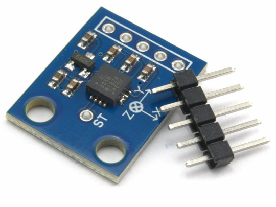
The ADXL335 Module is a compact and energy-efficient 3-axis accelerometer that provides signal conditioned voltage outputs. ADXL335 Module has a minimum full-scale range of ±3 g for accurately measuring acceleration.
This breakout board has the capability to measure both static gravity acceleration in tilt-sensing scenarios, as well as dynamic acceleration caused by movement, impact, or tremors. It is equipped with a built-in voltage regulator and operates seamlessly at 3.3V and 5V (3-5V).
An accelerometer is an electro-mechanical device capable of measuring both static and dynamic acceleration forces. This includes the constant force of gravity acting on your feet, as well as any movement or vibrations that may affect the device.
Systems such as FPV, RC, and Robots.
Navigation systems that utilize GPS technology
Acknowledging and recording the effects.
Devices used for gaming and virtual reality experiences
Features that are activated by movement.
Efficient energy conservation for portable devices.
Monitoring and compensating for vibrations
The detection of free-fall.
Detecting 6D orientation
The characteristics include:
One feature on the board is a Low Dropout (LDO) Voltage Regulator.
Can be connected to either a 3V3 or 5V Microcontroller.
With an ultra-low power consumption rate of only 40uA in measurement mode and an impressive 0.1uA in standby at 2.5V, this device ensures efficiency without compromising on performance.
This feature includes the ability to detect taps and double taps.
A feature for detecting free-fall is included.
The analog output has been successfully connected to the device and is now functioning properly.
Incorporate an ultra low noise linear LDO voltage regulator.
The device contains built-in onboard filters that effectively minimize noise from the motor and other high current electronics.
All sensors on the I2C bus
By using a soldered jumper, it is simple to choose two I2C addresses for the MPU6050.
The LED indicating power.
Incorporate a Logic level converter for I2C connectivity.
Optimized for 5V logic
1 note
·
View note
Text
Experience Seamless Home Automation: C-Bus Repairs Gold Coast
Is your C-Bus home automation system experiencing glitches? Don't let flickering lights or unresponsive controls disrupt your comfort. Here on the Gold Coast, you have access to reliable and professional C-Bus repair Gold Coast to restore your smart home to peak performance.
What is C-Bus?
C-Bus, developed by Clipsal, is a widely used technology for home automation. It allows centralized control over lighting, blinds, security systems, air conditioning, and more. With C-Bus, you can create customized scenes, automate tasks, and enhance your overall living experience.
Why Choose Professional C-Bus Repairs?
While C-Bus systems are generally reliable, occasional issues can arise. Here's why seeking professional help is the best course of action:
Expertise: Certified C-Bus technicians possess a deep understanding of the system's intricacies. They can quickly diagnose problems, identify the root cause, and implement effective solutions.
Safety: Electrical systems should only be handled by qualified professionals. C-Bus repairs often involve working with low-voltage wiring, but even minor electrical work requires expertise to ensure safety.
Warranty Protection: Attempting DIY repairs might void your C-Bus system warranty. Professionals use genuine parts and adhere to recommended protocols, safeguarding your warranty coverage.
Preventative Maintenance: Regular C-Bus maintenance by a qualified technician can identify potential problems early on, preventing future breakdowns and ensuring optimal system performance.
What to Look for in a C-Bus Repair Service
When seeking C-Bus repairs on the Gold Coast, consider these factors:
Experience: Choose a company with a proven track record and extensive experience in C-Bus systems.
Qualifications: Ensure technicians are certified and hold the necessary licenses for electrical work.
Guarantees: Look for companies offering warranties on their repairs, demonstrating confidence in their work.
Communication: Select a service provider that offers clear communication, keeping you informed throughout the repair process.
Customer Service: Positive customer reviews and a commitment to excellent service are hallmarks of a reliable company.
Benefits of Professional C-Bus Repairs
By choosing a reputable C-Bus repair service on the Gold Coast, you can expect:
Prompt Diagnosis and Repair: Get your smart home system back up and running quickly with minimal disruption.
Long-Term System Health: Preventative measures and proper repairs ensure your C-Bus system functions optimally for years to come.
Peace of Mind: Experience the comfort of knowing your smart home is in the hands of skilled professionals.
Investing in professional C-Bus repairs Gold Coast is an investment in your comfort and peace of mind. Don't hesitate to contact a qualified service provider on the Gold Coast to restore your smart home to its full potential. For More Info - https://cbusrepair.com.au

1 note
·
View note
Text
Data Acquisition System
Introduction:
Data acquisition (DAQ) System are parts of the modern engineering and scientific operations for measurement, monitoring and control of physical quantities. DAQs are widely being employed in sectors such as aerospace and defence, telecommunication, automobile industries and others to obtain finer picture of the functioning of systems, processes and equipment’s. Integrated data acquisition system are particularly developed with modular Data Acquisition (DAQ) system and Control systems that include outlook-specific built-in modules for signal conditioning, data logging, bus monitoring, and multiple outputs.

What Is DAQ?
Data Acquisition (DAQ) and Control System are essential parts of complex signal conditioning and related functions prevalent in state-of-the-art technologies, which are designed to acquire data from sensors, transducers, as well as various other devices. Another feature is modularity which makes it possible to adjust the system, develop additional functionalities and change the overall design in a number of ways.
DAQ system contain sub-systems where each sub-system performs a predefined role in measuring data as accurately as possible. Signal conditioning may include methods like signal amplification, filtering, noise reduction and signal calibration in order to provide a perfect environment that enhances the chances of precise and accurate signal data collection. SAPs require advanced modular DAQ system for its operations.
Why Data Acquisition (DAQ) System is a crucial component in the development and management of any project?
Data acquisition system are crucial for transforming raw data into reliable information for decision-making, troubleshooting, and optimization. They also require input signal conditioning to ensure data integrity, stability, and consistency. Strong channel conditioning systems ensure accurate data acquisition in difficult environments, even with complex signal sources.
How does a digilogic system data acquisition equipment work?
Digilogic Systems DAQ System is a modular technology best suited in harsh environments including an ability to withstand vibrations and high and low temperatures. It translates data gathered from modules into PCs or laptops for processing and analysis with Ethernet connectivity data and LAN. Communication is achieved through Wi-Fi technology, GSM or 3G for the remote and real-time data transfer. Meet the need for a fully integrated design for dependable application for aerial, automotive, and industrial uses.
Applications of Digilogic Systems Data Acquisition System:
Digilogic Systems Versatile Solutions in Different Industries
• Automotive Testing: Automated testing tool for vibration analysis, engine performance testing, and vehicle diagnostics.
• Aerospace and Defense: Rugged modules and precise data acquisition capabilities fulfill stringent requirements.
Product Specifications:
Processor: Power PC
Analog Output: Voltage, Current
Digital I/Os: TTL, Industrial (28V, 60V)
Serial: RS232/422/485
Communication: MIL-STD-1553B
Peripherals: Ethernet, USB
Operating temperature: -40°C to +70°C
Storage temperature: -40°C to +85 °C
Operating humidity: 10 to 90% RH
Storage humidity: 5 to 95% RH
EMI/EMC: MIL-STD-461C
Shock & Vibration: MIL-STD-810F
MIL-STD-461E with JSS 55555 qualification
Benefits of Digilogic Systems Data Acquisition System:
Digilogic System Benefits
• Strengthens day-to-day functioning and empirical decision-making.
• Provides assurance of accuracy and certainty which helps one in coming up with/ making decisions.
• It can be easily installed and adjusted depending on its use and requirements of the task at hand.
• Serves as the capacity, evolving in relation to the data acquisition criteria.
• Provides assurance of its availability with the customer base and customers benefiting from less time spent off from reaching different regions and those hard to reach areas.
• Uses COTS for ISO reasons and economical gain. GRAND THEOREM PREAMBLE: Adapts the specified COTS units for cost efficiency and improved system performance.
Conclusion:
The current data acquisition system at Digilogic Systems is more versatile, Macao-type modules and it is robust and perfect for use in the vibration monitoring systems. It enables to perform signal conditioning, data acquisition and bus analysis. Hence the Fin Drone solution comes with a unique solution for endless customization and compatibility with data transfer technologies such as Ethernet, Wi-Fi, GSM and 3G, such makes Fin suitable for usage in so many industrial and study areas.
Contact us today to discuss your Data Acquisition System requirements
Website: https://www.digilogicsystems.com/
Phone: Hyderabad: (+91) 40 4547 4601 / 02 / 03 Bengaluru: (+91) 80 4975 6034 Email: [email protected]
Locations: HEAD OFFICE
102, 1st Floor, DSL Abacus Tech Park Beside DSL Virtue Mall, Uppal, Hyderabad, Telangana-500 039, India
BRANCH OFFICE
216, 3rd floor, Zareen Heights, Varthur Road, Nagavarapalya, C. V. Raman Nagar, Bengaluru, Karnataka — 560093
#DAQ#digilogic systems#data acquisition system#aerospace#defense#technology#innovative solutions#DAQ System
0 notes
Text
How to Choose the Right Low Voltage Distribution Panel?
The main control of the electrical system is a low-voltage distribution panel that is responsible for transferring power throughout the building complex. Choosing the right one allows you to save your life, use the lift safely, and have a better future.
The guide will outline the procedure to identify the most suitable low-voltage distribution panel for your space.
Understanding Low Voltage Distribution Systems for Small-Scale Industries:
Feeders, called low-voltage distribution panels, as well as breaker panels or consumer units, usually include circuit breakers of various wattages. They perform the role of defenders; they immediately cut off power during emergencies, e.g., because of overloads or short circuits, thus protecting the wires and appliances from damage. Multi-circuit breakers measure the incoming power flow and send it to the various wires where electricity is distributed.
Key Factors for Choosing a Panel:
Here are the crucial aspects to consider when selecting a low-voltage distribution panel:
● Amperage Rating: It indicates the largest current that the panel can handle without the components getting damaged by an overload. A 200-ampere rating should be higher than the amperage of all the circuits you will be feeding.
● Number of Poles: Poles differ in their number, and conductors make a two-pole one-phase panel or three poles (3 or 4 poles) to be a three-phase panel. Selecting junction boxes that correspond to the incoming power source type (single or three-phase) is highly recommended.
● Number of Ways: This is a count of breaker slots that occupy the entire panel. Make sure that the same panel will have enough slots for your present and future feeders, as well as any equipment that you might need to install. Or you can give some more possible ways to have a later development.
● Main Breaker Rating: Apart from protecting the panel from overload, the circuit breaker provides such protection. The circuit breakers' capacity rating should be higher than the sum of all branch circuits and less than the total power.
● Busbar Rating: The bus is the copper bar inside the panel that provides current throughout the panel. The amperage rating should equal or more than the circuit main breaker rating.
Enclosure Type: The panels are available in different types of enclosures, known as indoor, outdoor, and weatherproof. The selection of appropriate material is mandatory according to the location where the installation will be done, keeping in mind dust, moisture, and possible effects of impact.
Additional Considerations
● Brand and Quality: Opt for the established brands famous for compliance with design standards and using high-quality materials.
● Knockouts and Cable Entry: Ensure the enclosure has enough knockouts and cables for your wiring needs.
● Grounding System Compatibility: The properly grounded system should also be able to fit your existing electrical system's grounding scheme.
● Local Regulations: Make sure that the designed panel requirements meet the existing electrical security standards in your locality.
Consulting a qualified electrician
Contact a professional licensed electrician for more complicated electrical systems. They will be able to evaluate your exact load, existing wiring layout, and various future ideas to match the best low-voltage distribution panel for your exact case. A good way to make this choice is by carefully considering these factors as well as seeking help from professionals if needed to select a low-voltage distribution panel that guarantees optimum power, safety, and flexibility for your electrical system now and in the future. Explore low-voltage distribution systems for small-scale industries from authentic manufacturers.
0 notes
Text
IP65 Waterproof Electric Gripper
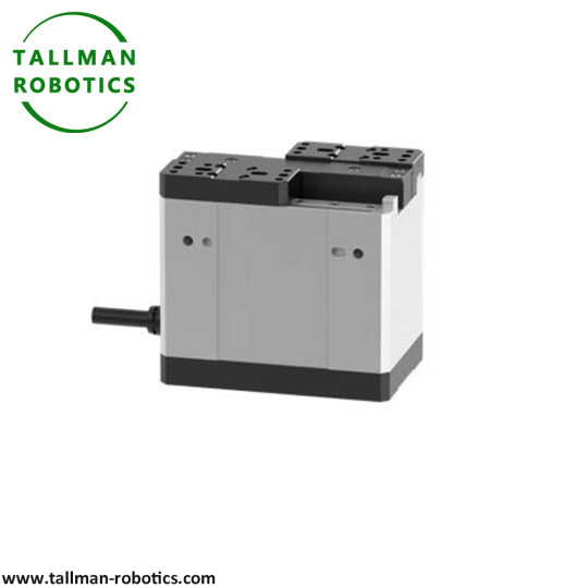
This IP65 Waterproof Electric Gripper is a high-performance device designed to handle challenging environments with ease. With its robust construction and advanced waterproofing capabilities, this IP65 Waterproof Electric Gripper offers reliable and precise gripping functionality in various industries.
In terms of waterproofing, IP65 rating indicates that the gripper has good dust-proof and waterproof performance.
This is usually achieved through sealing design and protective measures to prevent dust and water from entering the interior of the gripper. To ensure waterproof performance, the outer shell of the gripper usually adopts a sealed structure, which may include sealing rings, gaskets, or other sealing components. These sealing measures can prevent water and dust from entering the internal electronic and mechanical components of the gripper IP65 Waterproof Electric Gripper is engineered to withstand exposure to water, dust, and other elements, making it suitable for outdoor and industrial applications. The IP65 rating ensures that it provides protection against ingress of both solid particles and low-pressure water jets, allowing it to operate reliably in wet or dusty conditions. Featuring electric actuation, IP65 Waterproof Electric Gripper offers precise control and positioning, enabling accurate handling of objects. It can be seamlessly integrated into automated systems, enhancing productivity and efficiency. The waterproof design eliminates the need for additional enclosures or protection, reducing complexity and costs. Whether used in manufacturing, robotics, automotive, or any other industry that requires rugged and waterproof grippers, IP65 Waterproof Electric Gripper delivers consistent performance and durability. It offers a reliable solution for handling objects in harsh environments, ensuring smooth and efficient operations. With its compact size and versatile design, it can adapt to different setups and applications, providing a flexible and efficient gripping solution. Items Technical Parameters Product code TM-MFGB-08-80-1-D0300-ITG Size code 08 Stroke(mm) 80 Max clamping force 150N Max payload(kg) 3 Maxs speed open/close 0.7/0.7(s) Allowable load(Nm) MR:5.5 , MP:3.7 , MY:3.1 Positioning repeatability ±0.03(mm) Weight(kg) 1 Control method Bus Communication protocol Modbus RTU Rated voltage(V) DC24±10% Rated current(A) 4 Ambient environment 0 ~ 40℃,85%RH ( below ) IP rating IP65/IP55 In addition to industrial and outdoor applications, IP65 waterproof electric grippers can also be widely used in the following fields: 1. Medical Equipment: In the medical industry, this IP65 Waterproof Electric Gripper can be used for the operation of medical equipment, such as surgical robots, laboratory automation equipment, etc., to ensure accurate clamping and operation in clean and humid environments. 2. Food processing: The food processing field requires frequent cleaning of equipment. The IP65 waterproof electric gripper is suitable for food processing and packaging machinery, and can work stably in humid production environments. 3. Oceans and Ships: The waterproof requirements for equipment in the field of ships and oceans are very high, and this clamp can be used for marine exploration equipment, ship automation systems, etc. 4. Laboratory and scientific research: In scientific research laboratories, IP65 Waterproof Electric Gripper may need to come into contact with various liquids or operate in humid environments, and its IP65 waterproof characteristics make it suitable for such applications. 5. Automotive and Transportation: During the manufacturing and maintenance process of automobiles, grippers can be used to grip and operate components, especially in work involving water washing or humid areas. 6. Agriculture and Horticulture: Agricultural and horticultural equipment is often exposed to outdoor environments, and grippers can be used for automated irrigation systems, agricultural product harvesting machinery, etc. 7. Energy and Power: In the energy and power industry, such as the maintenance of wind turbines and solar equipment, waterproof clamps can be used to clamp and operate components. 8. Underwater robots: Underwater robots require waterproof clamping devices to perform various tasks, such as sampling and detection. 9. Electronic Equipment Manufacturing: In the electronic manufacturing process,IP65 Waterproof Electric Gripper can be used to clamp and assemble sensitive electronic components, and their waterproof characteristics help prevent component damage. These are just some possible application areas. In fact, the applicability of IP65 waterproof electric grippers can be extended to more fields according to specific needs and innovative applications. Its waterproof performance and electric driving method give it great advantages in clamping operations that require water resistance, moisture resistance, or special environmental conditions. You are welcome to watch more projects or visit our website to check other series or load down e-catalogues for further technical data. Youtube: https://www.youtube.com/@tallmanrobotics Facebook: https://www.facebook.com/tallmanrobotics Linkedin: https://www.linkedin.com/in/tallman-robotics Read the full article
#Electricactuator2-fingerGripper#IP65DustProofElectricGripper#IP65DustproofElectricGrippers#IP65OutdoorWaterproofElectricalGripper#IP67WaterproofElectricGrippers#LongStrokeElectricGripper#WaterResistantElectricGrippers
0 notes
Text

T-216 600A portable contact resistance test set
The risk of overheating is becoming more serious due to the fact that today's distribution networks have to carry heavier loads. Checking contact resistances at regular intervals detects faults before they cause overheating. T-216 600A Contact Resistance Test Set are used to measure contact resistances in high voltage breakers, disconnecting switches (isolators), knife-contact fuses, bus joints, line joints etc. T-216 contact resistance tester adopts the top open structure or vehicle mounted horizontal chassis. It has that vantage: more small volume, more light weight, more strong functions, and the simple operation. It designed for field tester design. The high output voltage is 10V. Display is 160*128 large LCD screen. Test current optionally, test time can be set, test process dynamic tips, suitable for different working environment. It can save 200 test record, the records can be printed and uploaded to the computer. Test range 0-20000.0μΩ (100Amp) 0-10000.0μΩ (200Amp) 0-6000.0μΩ (300A) 0-5000.0μΩ (400A) 0-4000.0μΩ (500A) 0-3000.0μΩ (600A)
1 note
·
View note
Text
What is the price of the tower -type bus (which is better for Guangdong CNC's parent arrangement machine)
The bus machining machine is mainly suitable for high and low pressure switch cabinets and transformer manufacturing industries. It is used to process copper and aluminum parent lines of various specifications. As long as the corresponding processing unit can be performed separately on the corresponding processing unit . The parent line machine is convenient and the production efficiency is higher than the traditional bus processing equipment. The work itinerary of each unit can easily adjust and reduce processing assistance time, and improve production efficiency. By replacing molds, it can also achieve multiple processing functions, such as pressure pressure Flowers, flattening, voltage cable joints, buttons, etc. are equipped with foot wheels on the machine. By adjusting the four supports, it can be easily moved
In order to improve the service life of CNC busbar bending machine, the use environment of CNC equipment is generally required to avoid direct exposure of sunlight and other thermal radiation, and to avoid places with too humid, too much dust, or corrosive gas. Corrosion gas can easily cause electronic components to be corroded and deteriorate, resulting in poor contact between contact or components, affecting the normal operation of the equipment. Precision CNC equipment should be far away from the equipment with large vibrations, such as punching and forging equipment. What is the price of the tower -type buser
Copper row bus is convenient for maintenance: The bus slot does not have to be maintained. Daily maintenance usually measures the temperature rise of the shell and the bus connector, the joint temperature of the connector in the line box, and whether the fastener is loose.
The punching unit adopts a six -mold turning tower structure. It does not need to replace the mold operation to improve the efficiency. It can be customized according to the user requirements. The mold material is made of high -quality steel. There is no burrs on the smooth surface.
As much as the price of the transfer of the tower -type parent wire is accelerating the technology upgrade and transformation of the enterprise technology, promoting the industry's movement to the mid -to -high -end specific specifications, this meeting expounds the future path of the future under the three dimensions of the policy framework of "Made in China 2025": Release the Industry Industry: Release Industry Enterprise technical reform upgrade guidance directory, compile annual key technical reform upgrade project guidance plans, guide social funds and other factors such as factors; simplify preliminary procedures, study and promote technical reform and upgrade projects that meet the conditions and do not need to add construction land; Financial and tax support, innovate the use of financial technical reform of the central government, improve the efficiency of funds, and encourage local finances to increase support for technological reform and upgrading. From 94 special pilot projects and 46 intelligent manufacturing demonstration pilot projects, to the release of road maps of Made in China, the policy side has continuously released dividends. This policy once again emphasizes the transformation and upgrading of intelligent manufacturing and manufacturing, and carries out production line transformation for traditional industries. Provide good policy support.
I believe everyone is very familiar with the copper row processing machine, but do you want everyone to understand the production technology of the copper row processing machine? In order to make everyone better operate the copper row processing machine, the following introduces the production process requirements of copper volume processing machines
The application of the parent wire machine in the field of electrical manufacturing is the most widely used. The development of the domestic electrical industry has always been in a very fast state. The development of the parent wire machine industry has always been coexisting. It is still in the low -to low level of technical power. What are the problems of the current parent line mechanism?
It is essential to clean up and lubricate the device. Establishing maintenance records can effectively judge and analyze the status of the equipment, thereby targeted preventive maintenance.
0 notes
Text
Common Applications and Benefits of Allen-Bradley Armour Blocks
A DC-bus power source for the Kinetix 5700 servo drive is the Allen-Bradley 2198-P031. It features a three-phase, A 47-63 Hz frequency, 324 - 528V (480V normal) RMS AC input voltage. It has a 55mm wide module. It has a main AC input current of 11.2 A, a max inrush current of 33 A (0-peak), and a peak AC input current of 33.4 A. The output current-to-bus for continuous and peak conditions is 10.5A and 31.6A, respectively. The power-to-bus for continuous and peak output is 7 kW and 21 kW, respectively. The internal shunt resistance and shunt power of the 2198-P031 are 37.5 and 75W, respectively. It has a 99% efficiency, a 129 J capacitive energy absorption capacity, and an internal capacitance of 585Î14F. With its novel snap-fit mechanism, the 2198-P031 power supply requires no they are simple to put together and install in the drive. Dimensionally, it measures 9.29 x 2.17 x 14.09 in. and weighs 9.55 lbs.
A major physical barrier defending ships and other space structures are armour blocks. Although basically similar to regular Hull blocks, armour increases the structure's overall Hit Points by 6.25 times and has an equal capacity for taking damage to individual blocks. Therefore, it is the first way of iron protection that is now available. Integrity Field Generators constructed of titanium further strengthen this method of protection. The fact that it stops Railguns from damaging the blocks it is protecting adds another layer of defence against these weapons. Nevertheless, it should only be utilised sparingly because armour blocks are 66% heavier and a significant cause of mass inflation.
I/O Modules for ArmorBlocks
allen-bradley armor block, Bulletins 1732D and 1732ES-IB8XOB8, offer inexpensive, armoured I/O that is suited for on-machine use. These modules can be installed on a machine adjacent to the sensors and actuators to reduce the length of the wire runs for high-speed packing, material handling, and automotive applications. These modules are appropriate for usage in end-of-arm robot applications and are offered for DeviceNet and EtherNet/IPTM networks.
It is possible to enchant armour to increase protection or make it resistant to certain forms of harm that it would not ordinarily be able to withstand, such as fall damage or fire (there are also other special enchantments for armour). The durability of the armour is not decreased by enchantments that reduce damage.
0 notes