#3D-CAD
Explore tagged Tumblr posts
Visit Tumblr Blog
Explore Tumblr blogs with no restrictions, modern design and the best experience.
Last Seen Tumblr Blogs


Fun Fact
12.7% of mobile users access Tumblr.
Text

#poll#tumblr polls#pollblr#cad#I guess#3d gizmo#idk anymore#I'm bad at tags#prev poll#reblog game#rb game#polls
175 notes
·
View notes
Text

Lucky and Sage are here to emotionally support me while I study for my test. The topic right now is additive manufacturing of polymeres.
It might sound ridiculous but it helps me remember what I need to learn when I explain it to them.
@paleopinesofficial thank you for the best study companions ever!
#linkle cad enigneer in training#lucky and sage by proxy cad engineers in training#newbie at 3d printing#dinosaurs are cool#parasaurolophus#sarcosuchus#paleopines#lucky paleo pines#sage the sarcosuchus#paleo pines
32 notes
·
View notes
Text
a fun pro tip is that if an online storefront has a "3D preview" of an object you can probably grab it as a glb file and throw it into blender with perfect scaling, full textures, and detailed dimensions that you can then pull off for other projects (or, like, I've seen people straight up dump Ikea furniture into blender scenes for animations)
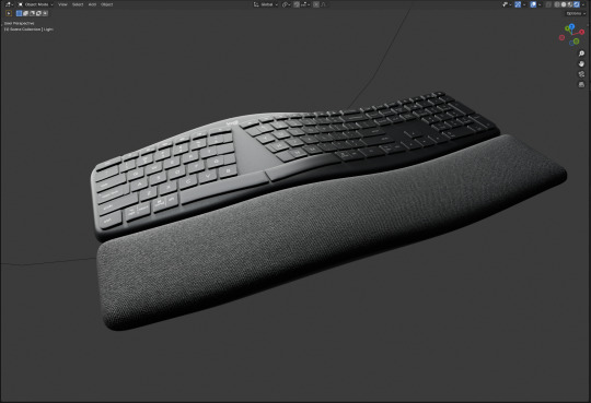
I want to add some printed parts to this keyboard and here's a perfect to-scale model I can reference and use to do boolean operations with to make my parts fit, even on complex curves
52 notes
·
View notes
Text

Leaf Weave Ring
Im looking to do some free custom 3D modeling. Shoot me a message if you're interested!
11 notes
·
View notes
Note
Hello, sorry to bother you, but you seem like one of the few around tumblr that has fun with CAD. Do you have any suggestions for us who'd love to learn CAD but pretty much has no schooling around us that teach these things? Thank you, love your blog!
I didn't have proper schooling I just learned through trial and error and tutorial videos (youtube is your best friend) and lots of googling/looking at forums. I also have the implicit requirement that I want to own my own tools so I don't tend to use the two largest 3d modeling softwares. The two main ones are Fusion360 (the most popular, but I don't know a good tutorial series for this) and OnShape. OnShape is browser based, Fusion360 is a windows application (get used to that if you want to do CAD work). I personally do 3d printing, and there are loads of youtubers who go into designing for 3d printing. I personally trust TeachingTech. This one uses OnShape.
youtube
I currently do my Modeling in FreeCAD, specifically the realthunder/link branch. which i believe is getting merged back into the proper "FreeCAD" soon(tm). I used this tutorial series by keep making.
youtube
I personally think he is a bit of a tool. but he showed me enough that I could learn either by trial and error or googling things I wanted to do. Just to avoid headaches, if you want to try FreeCAD i would recommend Ondsel instead, because its built from FreeCAD and includes a lot of things not currently in the stable release of FreeCAD (including the Link Branch I use). I'm simply familiar with the current UI and can't be assed to change.
#i hope this makes sense#i do want people to enjoy CAD work esp in the context of 3d printing#i find it fulfilling#invisibletripwire
10 notes
·
View notes
Text
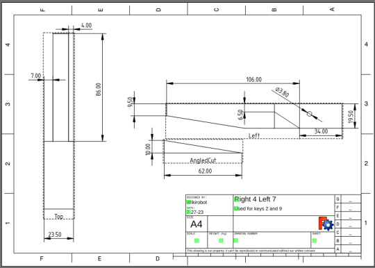
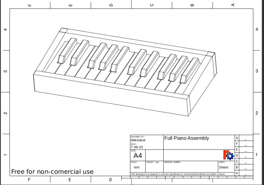
Want to build your own Piano Coat Rack?
I put together some plans for the Piano Coat Rack so that if anyone else wants to try to make one they have a starting point. I ended up putting them on itch.io for free since tumblr doesn't really like PDFs or zip files. The plans are free for non-commercial use. I also have a section describing some of the process to hopefully make it fairly easy to replicate.
I put these plans together in FreeCad, so along with a PDF version of the technical drawings there are also full 3D models that you can use to get a better understanding of how it goes together. If you notice any oddities or mistakes or have any question please just me up!
Also if you make one please tag me, I would love to see it!
Some Samples:

#woodworking#crafts#art#design#3d model#CAD#handtools#furniture#woodworking plans#technical drawings#piano#piano coat rack#sharing#free#hand tools#wood carving#plans#guides#finishing#maker#diy#freecad
62 notes
·
View notes
Text


#they've got that .DWG in them#she's got that .DWG in her#he's got that .DWG in him#font: monaspace krypton#engineering humor#CAD#AutoCAD#AutoDesk Revit#AutoDesk#Revit#foldmorepaper#wordart#program: xara 3d maker#xara3dmaker#gif#transparent#word art#text gif#engineering#mechanical engineering#MEP#architectural engineering#civil engineering#engineer#DWG#drafting
6 notes
·
View notes
Text
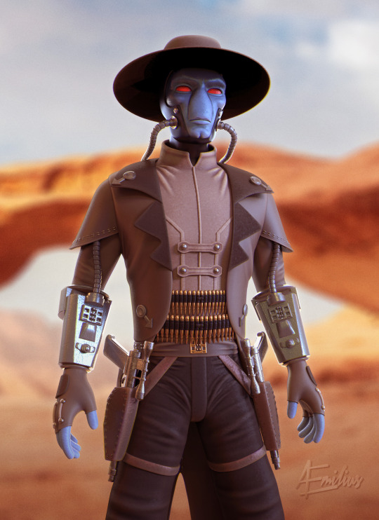
Daily Challenge 2024, Day 22. This is my 3D sculpture of Cad Bane, the bounty hunter, from "STAR WARS: The Clone Wars".
youtube
#zbrush#3d sculpting#keyshot#render#fan art#daily challlenge#turntable#cad bane#star wars#clone wars#bounty hunter#Youtube
13 notes
·
View notes
Text
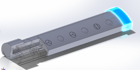
Friend bought this fan with UV reactive ink on it, but it didn't have UV lights to make it glow all the time. So we added some.
Designed the battery compartment to be printed and slide onto the handle, and did the wiring/battery design. Used dryer sheets to reflect the light back to the front, it worked super well.
I forgot to get a picture before she went to Dinolands and it got given away there, so no picture, but yeah.
I really want to make a rave mask, but I'm busy and haven't made progress on it yet.


25 notes
·
View notes
Text
Transitioning with Technology in AEC: From AutoCAD to BIM

CAD was introduced to ease the complexities of traditional practices. It was a powerful tool until BIM extended the services multiple benefits. Transform from AutoCAD to BIM for efficient and accurate construction projects. Continue reading to know the importance.
#cad to bim#cad to bim services#cad to bim conversion#cad to revit#cad to revit services#autocad to bim conversion#autocad to revit#pdf to bim#pdf to revit#pdf to bim services#pdf to 3d model#pdf to revit services#pdf to bim conversion services#cad to bim modeling services#cad to revit converter#autocad to bim services
2 notes
·
View notes
Text
MCR Interior Design (Solo Project Task) - 2010

#MCR#mcr tour#empower#promote#service#marketing#branding#presentation#3d cad modeling#3d render#design#digital art#portfolio#artist#automotive design#concept#umarali#khokhar#bristol#umi3-nous design#technology#futuristic#ideas#innovation#artwork#UK#tech skills#self taught designer
3 notes
·
View notes
Text
My 3D-printer is driving me nuts right now. It's a constant spaghetti festival whenever I try to print one specific thing. A thing that was printing perfectly fine yesterday but today it just won't. Everything else works just this one model...
4 notes
·
View notes
Text
it asploded
19 notes
·
View notes
Text
Submit your jewelry ideas and I will model and render them!

#for freeeee#3d cad modeling#3d cad#cad cam#custom jewelry#silversmith#goldsmith#jewelry#graphic design#3d design
3 notes
·
View notes
Text
A genuine honest to goodness question here, does anyone around here know of professional CAD modellers (furry very much preferred!) who would be willing to take on some paid work, or at the very least offer some advice? I know it's a longshot, but still gotta ask!
This is not for me personally, but for a client of mine who I think would benefit from CAD over polygonal modelling for their project.
Reposts certainly appreciated! 🙏
5 notes
·
View notes
Text
I’m back in school and also back to working on projects, I have lots of ideas I want to start of but what I’ve done in the first week is this, I got fabricated the new design for the driving mechanism and got it working!
This version needs some adjustment as the side walls have their dimensions all wrong so the parts don’t fit together right. This is mostly because I also changed how the structural struts are fitted. Now instead of using screws the plan is to have a tension fit. Then to get the spacing right I’ll have the laser cutter etch on to the ends of the struts, making them a bit thinner and able to fit into the holes
I’ve also got a whole new assembly model now, now made on the updated version of FreeCAD, it was fairly hard to make as FreeCAD doesn’t support assemblies by default, because I don’t need this one to move just putting the parts in the right spaces is enough
I’m a bit sick right now but I’m going to keep going this semester and hopefully get back up to speeds with making new things!

#engineering#design#mechanism#cad#robotics#biotech#bugs#robot#leg#machinery#lasercutting#wood#3d printing
2 notes
·
View notes