#i2C
Explore tagged Tumblr posts
Text
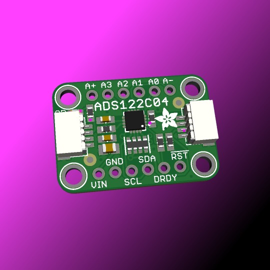
We stock and use a couple of different I2C ADCs, such as the NAU7802
and the HX711
Both of these are kinda designed specifically for load cells. This is a more general-purpose 24-bit ADC using the ADS122C04
with adjustable 1x to 128x gain, up to 2ksps and an internal reference. It can be single or differential input. Good for sensitive things like RTDs, thermocouples, or resistive bridges like load cells! Coming soon.
#adafruit#ADS112C04#24bit#4channel#i2c#adc#NAU7802#loadcells#ti#texasinstruments#rtd#thermocouples#24bitadc#analogtodigital#electronicsdesign#sensormeasurement#embeddedhardware#differentialinput#internalreference#gaincontrol#highresolution#texasinstrumentsadc#sensorinterface#loadcellapplications#precisionelectronics#thermocouplesupport#rtddesign#adcdesign#i2cinterface#resistivebridges
11 notes
·
View notes
Text
Understanding ESP32 Pin Configuration: A Developer's Guide
The ESP32 microcontroller has become a cornerstone of IoT development, thanks to its versatility and powerful features. One of the most crucial aspects of working with ESP32 is understanding its pin configuration and capabilities. Let's dive into the essential aspects of ESP32 pins that every developer should know.

GPIO Pins Overview
The ESP32 boasts up to 34 GPIO (General Purpose Input/Output) pins, but not all are available for use in most development boards. Some key points about ESP32 pins:
GPIO 6-11: Reserved for internal SPI flash connection
GPIO 34-39: Input-only pins with no internal pull-up/pull-down resistors
ADC Capabilities: Two 12-bit SAR ADCs, supporting 18 measurement channels
Touch Sensors: Up to 10 capacitive touch GPIOs
Special Function Pins
Several pins serve dual purposes or have specific functions:
Boot Mode Pins GPIO 0: Bootloader mode when pulled low during reset GPIO 2: Connected to on-board LED in many development boards
UART Pins GPIO 1 (TX) and GPIO 3 (RX): Default UART0 communication Often used for flashing and debugging
SPI Pins VSPI: GPIO 5 (CS), 18 (CLK), 19 (MISO), 23 (MOSI) HSPI: GPIO 14 (CLK), 12 (MISO), 13 (MOSI), 15 (CS)
Best Practices for Pin Usage
Strapping Pins Always check the strapping pin status before using GPIO 0, 2, 4, 5, 12, and 15. These pins may affect boot behavior if incorrectly configured.
Input-Only Pins When designing sensor interfaces, prefer GPIO 34-39 for analog inputs as they're input-only and less susceptible to noise.
Pull-up/Pull-down Configuration
ADC Usage ADC1: Can be used with Wi-Fi/Bluetooth active ADC2: Only available when Wi-Fi/Bluetooth is disabled
Common Pitfalls to Avoid
Don't use GPIO 6-11 in your projects as they're connected to the internal SPI flash.
Avoid using strapping pins for critical functions that can't be changed during boot.
Remember that GPIO 34-39 don't have internal pull-up/pull-down resistors.
Be cautious with voltage levels - ESP32 pins operate at 3.3V.
Conclusion
Understanding ESP32 pinout is fundamental for successful project development. By following these guidelines and best practices, you can avoid common issues and make the most of your ESP32's capabilities. Remember to always consult the official ESP32 technical reference manual for detailed specifications and updates.
#ESP32 #PinConfiguration #DevelopersGuide #Microcontrollers #EmbeddedSystems #IoT #Programming #Hardware #Electronics #Arduino #ESP32S2 #ESP32C3 #ESP32C2 #ESP32C6 #ESP32S3 #ESP32H2 #ESP32P1
#ESP32#microcontroller#pinconfiguration#GPIO#ADC#DAC#I2C#SPI#UART#PWM#analog#digital#input#output#microcontrollers#embeddedsystems#IoT#InternetOfThings#electronics#hardware#software#programming#development#Arduino#ESP8266#RaspberryPi#microcontrollerprogramming#embeddedprogramming#IoTdevelopment#electronicdesign
1 note
·
View note
Text
https://www.futureelectronics.com/p/semiconductors--comm-products--i2c/pca9532pw-112-nxp-3036484
I2C communication protocol, liquid crystal displays, clock line
PCA9532 Series 5.5 V 350 uA 400kHz SMT 16-bit I2C-bus LED Dimmer - TSSOP-24
#Comm Products#I2C#PCA9532PW#112#NXP#I2C communication protocol#liquid crystal displays#clock line#Bus interface connection protocol#Inter-integrated Circuit#I2C-Bus#I2C circuit diagram#i2c protocol programming#Inter-Integrated Circuit
1 note
·
View note
Text
https://www.futureelectronics.com/p/semiconductors--comm-products--i2c/pca9532pw-118-nxp-5033862
16-bit I2C-bus LED Dimmer, Embedded communication, image processing,
PCA9532 Series 5.5 V 350 uA 400kHz SMT 16-bit I2C-bus LED Dimmer - TSSOP-24
#NXP#PCA9532PW#118#Comm Products#I2C#16-bit I2C-bus LED Dimmer#Embedded communication#image processing#High-Speed#Isolated CAN Transceiver ICs#CAN bus lines#i2c modules#Can Power Systems#CAN transceiver#Ethernet MAC controller
1 note
·
View note
Text
https://www.futureelectronics.com/p/semiconductors--comm-products--i2c/pca9515adp-118-nxp-7183946
What is I2C communication, serial communication bus, I2C logic
PCA9515A Series 3.6 V 5 mA 400 kHz 6 pF I2C-bus Repeater - SOIC-8
#NXP#PCA9515ADP#118#Comm Products#I2C#What is I2C communication#serial communication bus#I2C logic#Surface Mount I2C bus repeaters#Wire Interface Bus#USB to I2C converter#Encoder motor driver#i2c communication protocol#I2C bus switches
1 note
·
View note
Text
https://www.futureelectronics.com/p/semiconductors--comm-products--i2c/pca9532pw-118-nxp-5033862
I2c bus, Embedded communication, Isolated CAN Transceiver ICs
PCA9532 Series 5.5 V 350 uA 400kHz SMT 16-bit I2C-bus LED Dimmer - TSSOP-24
#NXP#PCA9532PW#118#Comm Products#I2C#Ethernet MAC controller#communication protocol#i2c module#bus#Embedded communication#Isolated CAN Transceiver ICs#High-Speed CAN Transceiver#CAN transceiver#SPI bus#CAN bus lines
1 note
·
View note
Text
https://www.futureelectronics.com/p/semiconductors--comm-products--i2c/pca9515adp-118-nxp-5973557
I2c bus, I2c communication protocol, Inter-Integrated Circuit, spi interface
PCA9515A Series 3.6 V 5 mA 400 kHz 6 pF Surface Mount I2C-bus Repeater - SOIC-8
#Comm Products#I2C#PCA9515ADP#118#NXP#What is I2C communication#High Speed CAN#i2c pins#digital integrated circuits#I2c bus#I2c communication protocol#Inter-Integrated Circuit#spi interface#expanders#I2C bus repeaters
1 note
·
View note
Text
What are I2C devices, I2C in communication, i2c interface, ESD cards
PCA9532 Series 5.5 V 350 uA 400kHz SMT 16-bit I2C-bus LED Dimmer - TSSOP-24
#NXP#PCA9532PW#118#Comm Products#I2C#Surface Mount I2C-bus Repeater#low-speed devices#digital integrated circuits#Inter-Integrated Circuit#multi-controller#i2c pins#what are I2C devices#I2C in communication#i2c interface#ESD cards
1 note
·
View note
Text
accessibility online is super important and it's basically criminal that it's as bad as it is. we can, should, and must do better. that said the acronym a11y never fails to make me seethe with anger. terrible acronym it looks terrible, it's unclear what it is without context, it reads as leetspeek 'ally', etc. there were so many better choices and it just sucks massively.
or as i like to call it. a373y.
#kaia.mypost#if u have to write articles defending a11y as normal bc w3c uses it (no the fuck it doesn't#it's world wide web consortium it's like i2c not i18n)#then methinks ur acronym sucks shit#i18n makes sense it's a long ass word for a deeply specific field!! a11y is half the length and everybody needs to care abt it#also any post tagged a11y sucks shit and is half the time wrong and half the time meaningless. it feels like
35 notes
·
View notes
Text

A mini GPS from uBlox with I2C and UART 🛰️📡🔧
The SAM-M8Q
is an entry-level 'all in one' GPS from uBlox - it comes with both UART and I2C interfaces plus a built-in antenna so it's ready to go 'out of the box.' It's also fairly small, so we decided to try and make a little breakout for it. It exposes both interfaces, but we expect most folks will like using the Stemma QT port for instant I2C interfacing. We gotta dig into uBlox's interface since we expect the I2C to be a little more complex than the PA1010 we've used.
#adafruit#gps#ublox#i2c#uart#sam-m8q#stemma#pa1010#electronics#gpsmodule#makerspace#hardwaredesign#embedded#opensourcetools#diyprojects#techinnovation#electronicsprojects#gpsbreakout#prototyping#smalldevices#sensorintegration#microcontroller#makersmovement
7 notes
·
View notes
Text
Arduino Plug and Make Kit: Was ist drin und wie benutzt man es?
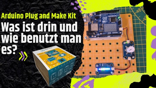
Es gibt von Arduino ganz neu das Arduino Plug and Make Kit, dieses enthält alles, was du für den Start in die Mikrocontrollerprogrammierung benötigst. Was in diesem Kit enthalten ist und wie du die Sensoren & Aktoren am mitgelieferten Arduino UNO R4 WiFi programmierst, erfährst du in den nächsten Abschnitten hier im Beitrag. https://youtu.be/B0mXN7ADJeg
Was ist im Arduino Plug and Make Kit drin?
Das Kit enthält neben einem Arduino UNO R4 WiFi nachfolgende Sensoren & Aktoren: - einen Rotary Encoder (mit Push Funktion) - einen Piezo Buzzer - ein Modul mit 3 Taster - ein Temperatur & rel. Luftfeuchtigkeits-Sensor - ein Distanzsensor Typ VL53L4CD - ein Modul mit 8 RGB LEDs - einen 6-Achsen Lagesensor Zusätzlich findest du am Arduino UNO R4 WiFi noch: - eine 8x12 LED Matrix (in rot), - einen ESP32-S3-Mini
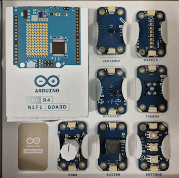
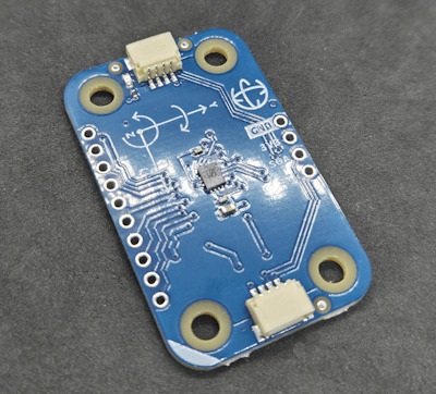
6 Achsen Sensor
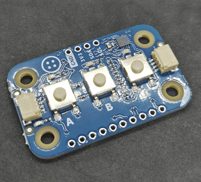
3fach Taster Modul
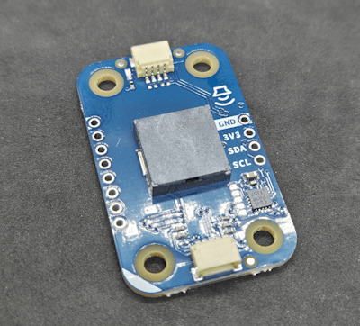
Buzzer
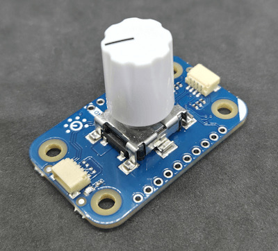
Rotary Encoder

Temperatur & rel. Luftfeuchtigkeits Sensor
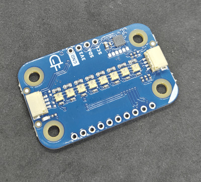
8fach LED Modul
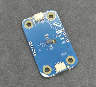
ToF - Distance Sensor
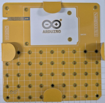
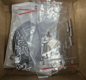
Zusätzlich findest du noch eine Modulino Base, auf welche du den Mikrocontroller und deine Schaltung mit den Sensoren & Aktoren aufschrauben kannst. Das sorgt dafür, dass deine Schaltung auf dem Schreibtisch nicht wild umherfliegt. Es ist dafür alles enthalten, du benötigst hier nur noch einen kleinen Kreuzschraubendreher (Größe PH0) und einen Maulschlüssel (Schlüsselweite 5,5). Die Sensoren werden über eine I2C Qwiic Schnittstelle mit dem Mikrocontroller verbunden und daher enthält das Kit zusätzlich noch einige Anschlusskabel.
Einrichten des Arduino UNO R4 WiFi in der Arduino IDE
Dem Kit liegt wie gezeigt ein Arduino UNO R4 WiFi bei, dieser ebenso neue Mikrocontroller verfügt über eine WiFi & Bluetooth Schnittstelle sowie eine LED Matrix schon allein damit könnte man viele Wochenenden verbringen und IoT Projekte umsetzen.
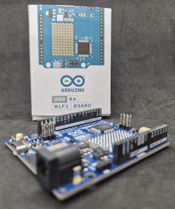
Bevor wir mit den ersten Schaltungen beginnen, richten wir diesen in der Arduino IDE ein, dieses ist bei der Version 2.x besonders einfach geworden.
Aufbau einer Schaltung
Zunächst möchte ich eine kleine Schaltung mit dem 8fach LED Modul sowie dem Rotary Encoder aufbauen. Über den Rotary Encoder kann man zum Beispiel die Geschwindigkeit eines Lauflichts oder die Helligkeit der LEDs steuern. Zusätzlich verfügt der Rotary Encoder noch über ein Tast-Event welches wir ebenso verwenden können, um die Farbe zu wechseln.
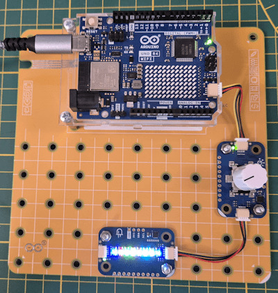
Arduino Plug and Make Kit - Schaltung mit 3fach LED Modul & Knob Die Sensoren & Aktoren am Arduino UNO R4 WiFi werden über die Qwiic Schnittstelle verbunden. Das Gute an dieser Schnittstelle ist, dass du die Module kaskadierend hintereinander verbinden kannst. (Im Bild siehst du zwei Module, welche miteinander verbunden sind.)
Programmieren der Sensoren / Aktoren in der Arduino IDE
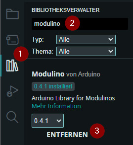
Damit wir die Module in der Arduino IDE programmieren können, benötigen wir eine zusätzliche Bibliothek. Diese lässt sich über den internen Bibliotheksverwalter mit wenigen Klicks installieren. Zunächst wählst du den Bibliotheksverwalter (1) und suchst dort nach "modulino" (2). Du solltest nun die Schaltfläche "INSTALLIEREN" an der Position 3 finden.
Ich werde jedem Modul im Kit einen separaten Beitrag & Video widmen, hier möchte ich dir nachfolgend an zwei Beispielen zeigen, wie diese programmiert werden. Auf der Seite https://courses.arduino.cc/plugandmake/ findest du viele coole Beispiele zu diesem Kit und der Arduino Cloud. Beispiel 1 - Programmieren der LEDs Am 8fach RGB LED Modul kannst du jede LED in diversen Farben anzeigen. Ebenso kannst du dort kleine Leuchteffekte für ein Lauflicht oder Fading programmieren. Ebenso kannst du über dieses auch die Werte des Distanz-Sensors oder Temperatursensors visualisieren.
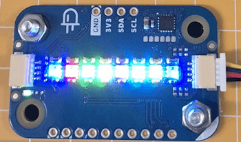
gesetzte Farben an dem 8fach LED Modul Programm - anzeigen verschiedener Farben auf dem 8fach LED Modul des Arduino Plug and Make KitHerunterladen //Bibliothek zum steuern / lesen //der Modulino Module #include //Objekt vom Typ ModulinoPixels erzeugen //in diesem Fall das 8fach LED Modul ModulinoPixels leds; //Ablegen von Objekten mit einem RGB-Farbwert ModulinoColor colorBlue(0, 0, 255); ModulinoColor colorRed(255, 0, 0); ModulinoColor colorGreen(0, 255, 0); ModulinoColor colorYellow(255, 255, 0); ModulinoColor colorPurple(128, 0, 128); ModulinoColor colorCyan(0, 255, 255); ModulinoColor colorOlive(128, 128, 0); ModulinoColor colorNavy(0, 0, 128); //Konstante für die Helligkeit der LEDs const int HELLIGKEIT = 10; void setup() { //beginn der I2C Kommunikation Modulino.begin(); //begin der I2C Kommunikation mit dem LED Modul leds.begin(); //setzen der Farbe an der LED //erster Parameter, der Index der LED //zweiter Parameter, die Farbe //dritter Parameter, die Helligkeit leds.set(0, colorBlue, HELLIGKEIT); leds.set(1, colorRed, HELLIGKEIT); leds.set(2, colorGreen, HELLIGKEIT); leds.set(3, colorYellow, HELLIGKEIT); leds.set(4, colorPurple, HELLIGKEIT); leds.set(5, colorCyan, HELLIGKEIT); leds.set(6, colorOlive, HELLIGKEIT); leds.set(7, colorNavy, HELLIGKEIT); //Der Wert für die Helligkeit kann entfallen, //da hier ein Default-Wert von 25 hinterlegt wurde! //Anzeigen der Farben leds.show(); } void loop() { //bleibt leer } Beispiel 2 - steuern eines Lauflichts mit dem Knob Am 8fach LED Modul habe ich ein kleines Lauflicht programmiert, welches mit dem Knob / Rotary Encoder in der Geschwindigkeit gesteuert werden kann. Da der Knob noch zusätzlich über ein Tast-Event verfügt, können wir diesen nutzen, um die Farbe zu wechseln. Programm - steuern eines Lauflichts mit dem Knob am Arduino Plug and Make KitHerunterladen //Bibliothek zum steuern / lesen //der Modulino Module #include //Objekt vom Typ ModulinoPixels erzeugen //in diesem Fall das 8fach LED Modul ModulinoPixels leds; //Objekt vom Typ ModulinoKnob erzeugen //in diesem Fall der Rotary Encoder ModulinoKnob knob; //Ablegen von Objekten mit einem RGB-Farbwert ModulinoColor colorBlue(0, 0, 255); ModulinoColor colorRed(255, 0, 0); ModulinoColor colorGreen(0, 255, 0); //Erzeugen eines Arrays mit den Farben ModulinoColor colors = { colorBlue, colorRed, colorGreen }; //Wert für die Helligkeit const int HELLIGKEIT = 5; //Feld für die Pause, //Der Wert wird aus der Position des Knob //berechnet. int pause = 0; //Aktueller Index für die Farbe int index = 0; //Konstante mit der maximalen Anzahl der Farben. const int MAX_COLORS = 2; void setup() { //beginn der I2C Kommunikation Modulino.begin(); //begin der I2C Kommunikation mit dem LED Modul leds.begin(); //begin der I2C Kommunikation mit dem Rotary Encoder knob.begin(); } //Funktion zum deaktivieren der LEDs void ledsOff(ModulinoColor color) { for (int led = 0; led < 8; led++) { leds.set(led, color, 0); } leds.show(); } //Funktion zum anzeigen einer Farbe void setLEDColor(ModulinoColor color, int index) { leds.set(index, color, HELLIGKEIT); leds.show(); delay(pause); } void loop() { //auslesen der Position vom Knob int position = knob.get(); //berechnen der Pause aus der Position pause = (position > 0 ? position : 1) + 25; //entnehmen der Farbe aus dem Array mit //dem aktuellen Index ModulinoColor color = colors; //Wenn der Knob gedrückt wird, dann... if (knob.isPressed()) { //prüfen ob der aktuelle Index gleich //der maximalen Farbe ist, dann... if (index == MAX_COLORS) { //Wert des Index auf -1 setzen. index = -1; } //erhöhen des Index um 1 index++; } //Schleife über die LEDs //von links nach rechts (von 0 bis 7) for (int led = 0; led < 8; led++) { //setzen der Farbe an der LED setLEDColor(color, led); } //deaktivieren der LEDs ledsOff(color); //Schleife über die LEDs //von rechts nach links (von 7 bis 0) for (int led = 7; led >= 0; led--) { setLEDColor(color, led); } //deaktivieren der LEDs ledsOff(color); } Read the full article
0 notes
Text
we did not in fact finish the lab due this morning or come even close BUT he’s giving us the next week with no late penalty bc it turns out one of the pins we were trying to use to communicate Actually Does Not Exist #slay
#personal#the engineering chronicles#it’s literally listed as an i2c pin in the tables but i overheard the student assistant say it’s not a real pin when i got into lab and was#like ?!?! and looked it up in the data sheet and for our version of this microcontroller yeah they replaced it with a capacitor for some#inexplicable reason and Left The Pin Label There. also need to stress that where it says it’s an i2c pin it IS listed under our specific#microcontroller like. technical writer of this data sheet when i catch you ‼️#so anyway. that was NOT the only issue we had even if the pin did exist it was supposed to be set for i2c2 and we accidentally set it for#i2c1 and also none of us has any clue what command to send to make the led on the other board like up but he doesn’t need to know that 🤫#*light up#even my prof didn’t know abt the secret nonexistent pin and he said no student of his has ever had this issue which actually i don’t think#is true bc i’ve been trying to avoid the b port all semester Specifically bc i remember having weird issues with the pins not working on it#last year and i suspect this is why but. yeah no consequences YIPPEE 🥳
3 notes
·
View notes
Text
https://www.futureelectronics.com/p/semiconductors--comm-products--i2c/pca9515adp-118-nxp-5973557
I2C CAN Bus Module, I2C adapter, I2C devices, Serial Peripheral Interface
PCA9515A Series 3.6 V 5 mA 400 kHz 6 pF Surface Mount I2C-bus Repeater - SOIC-8
#Comm Products I2C#PCA9515ADP#118#NXP#I2C CAN Bus Module#I2C adapter#I2C devices#Serial Peripheral Interface#I2C Level Converter#i2c protocol#spi protocol#uart protocol#i2c communication#i2c protocol in embedded system#I2C-bus Repeater
1 note
·
View note
Text
Infineon releases new NFC I2C bridge tag for contactless authentication and secure configuration of IoT devices
May 27, 2024 /SemiMedia/ — Infineon Technologies AG recently launched a high-performance NFC I2C bridge tag, OPTIGA™ Authenticate NBT, for single-tap authentication and secured configuration of IoT devices. It is the only asymmetric cryptography tag for sign and verify operations in the market certified as a Type 4 Tag by the NFC Forum. OPTIGA Authenticate NBT enables ultra-fast and seamless data…

View On WordPress
#electronic components news#Electronic components supplier#Electronic parts supplier#Infineon#NFC I2C bridge tag
0 notes