#what are I2C devices
Explore tagged Tumblr posts
Visit Tumblr Blog
Explore Tumblr blogs with no restrictions, modern design and the best experience.
Last Seen Tumblr Blogs


Fun Fact
In 2020, Tumblr had 29.4 million users in the US.
Text
What are I2C devices, I2C in communication, i2c interface, ESD cards
PCA9532 Series 5.5 V 350 uA 400kHz SMT 16-bit I2C-bus LED Dimmer - TSSOP-24
#NXP#PCA9532PW#118#Comm Products#I2C#Surface Mount I2C-bus Repeater#low-speed devices#digital integrated circuits#Inter-Integrated Circuit#multi-controller#i2c pins#what are I2C devices#I2C in communication#i2c interface#ESD cards
1 note
·
View note
Text

Fruit Jam RP2350B credit-card mini computer with all the fixin's 🍓🍇💾
We were catching up on a recent Hackaday hackchat with Eben Upton (https://hackaday.io/event/202122-raspberry-pi-hack-chat-with-eben-upton) and learned some fun facts: such as the DVI hack for the RP2040 was inspired by a device called the IchigoJam (https://www.hackster.io/news/ichigojam-combines-strawberry-and-raspberry-to-deliver-a-raspberry-pi-pico-powered-educational-micro-66aa5d2f6eec). We remember reading about this back when it was an LPC1114, now it uses an RP2040. Well, we're wrapping up the Metro RP2350 (https://www.adafruit.com/product/6003), and lately, we've been joking around that with DVI output and USB Host support via bit-banged PIO, you could sorta build a little stand-alone computer. Well, one pear-green-tea-fueled-afternoon later we tried our hand at designing a 'credit card sized' computer - that's 3.375" x 2.125", about the same size as a business card (https://hackaday.com/2024/05/07/the-2024-business-card-challenge-starts-now/) and turns out there's even a standard named for it: ISO/IEC 7810 ID-1 (https://www.iso.org/standard/70483.html).
Anyhow, with the extra pins of the QFN-80 RP2350B, we're able to jam a ridonkulous amount of hardware into this shape: RP2350B dual 150MHz Cortex M33 w/ PicoProbe debug port, 16 MB Flash + 8 MB PSRAM, USB type C for bootloading/USB client, Micro SD card with SPI or SDIO, DVI output on the HSTX port, I2S stereo headphone + mono speaker via the TLV320DAC3100 (https://www.digikey.com/en/products/detail/texas-instruments/tlv320dac3100irhbt/2353656), 2-port USB type A hub for both keyboard and mouse or game controllers, chunky on-off switch, Stemma QT I2C + Stemma classic JST 3-pin, EYESPI for TFT displays, 5x NeoPixels, 3x tactile switches, and a 16-pin socket header with 10 A/D GPIO + 5V/3V/GND power pins. The PSRAM will help when we want to do things like run emulations that we need to store in fast RAM access, and it will also let us use the main SRAM as the DVI video buffer.
When we get the PCBs back and assembled, what should we try running on this hardware? We're pretty sure it can run DOOM. Should that be first? :) We also need a name. Right now, we're just calling it Fruit Jam since it's inspired by the IchigoJam project.
#fruitjam#rp2350b#raspberrypi#microcomputer#hackaday#diyelectronics#retrocomputing#creditcardpc#hardwarehacking#usbhost#dvioutput#psram#retrogaming#makercommunity#opensourcehardware#homemadecomputer#minipc#embeddeddevelopment#techinnovation#electronicsproject#tinkering#cortexm33#doomport#custompcb#hacktheplanet#hardwaredesign#diytech#retroconsole#handheldgaming#fruitjampc
34 notes
·
View notes
Text
For future reference (my own and others), if your TI SilverLink USB cable stops working and starts showing up as "TUSB3410 Boot Device" or similar under device manager (AKA this issue on TI's help page), this is how you can fix it:
Download the TUSB3x10 EEPROM Burner. This is a Windows-only program, but to my knowledge will work on basically any windows machine from XP on -- so long as it's got USB ports. No clue if it'll work in a VM. (You might want to consult this user's manual.)
Download the SilverLink firmware. I got it from here, and compiled it from their de-compilation. It's just a standard 'make' to build. The output file you're looking for is called "ti_graph_link_silver.eep".
Rename "ti_graph_link_silver.eep" to "ti_graph_link_silver.bin".
Open the TUSB3x10 EEPROM Burner, click on the options dropdown and click "Show the 'Program Full Binary Image' button". (page 7 of the manual).
Select the entry under "Computer" labeled "TUSB3410 EEPROM Burner Instance (1.00)".
Set EEPROM size to "64Kb".
Set "File Path" to point to "ti_graph_link_silver.bin". (The renamed .eep, not the original .bin)
I don't know if the VID, PID, Manufacturer string, Product string and Serial # need to be set manually or not with a 'Full Binary Image' burn. Just to be safe, I set VID to 0451, PID to e001, Manufacturer to "Texas Instruments", Product to "TI-GRAPH LINK USB", and checked "Not Serialized"*.
Click the "Program Full Binary Image" button (yellow triangle with the exclamation point), and proceed with the write.
Unplug and re-plug your cable, and it should show up as a SilverLink again!
Additional notes:
The reason that this happens is because the SilverLink cable (revision b, at least) is based on the TUSB3410 microcontroller. That microcontroller's boot process involves checking for an I2C EEPROM containing program code. If it finds that EEPROM and its contents are properly formatted, it'll copy that code into internal RAM and start executing it. If it can't find the EEPROM, or its contents aren't properly formatted, it'll fall back to looking for boot code over USB. Thus: "TUSB3410 Boot Device". Your cable has, in essence, forgotten who it is and and is begging for you to give it a purpose.
The default page-write buffer size (32 bytes) and I2C bus speed (400 KHz) in the burner app are already correct, so no need to change them.
*I don't remember exactly what the Manufacturer string, Product string, or serial number fields were set to pre-corruption. Likewise, no idea about the advanced descriptor options. If someone wants to send the output of lsusb -v -s [whatever their silverlink's bus/id numbers are], I'd really appreciate it!
You might be able to skip the header rigamarole by taking the ti_graph_link_silver.bin file directly ("directly coming from the compiler") -- but I again I don't know exactly what information is in the .eep file and what isn't. Are the PID and VID encoded somewhere in there? I peeked with a hex editor but have no clue. If someone has hardware lying around they're willing to experiment with/potentially brick, I'd love to hear your results!
If you mess up and accidentally forget to do a "Full Binary Image" write, or otherwise brick the firmware, you can force the TUSB3410 to fall back to USB boot mode by opening the plastic shell around the PCB (one Torx screw under the sticker, then just normal plastic tabs) and shorting the right-bottom (Vss) and right-top (SDA), or right-bottom (Vss) and center right-top (SCL) pins of the EEPROM (the chip labeled "24LC64") as you plug it into the USB port. You may need multiple attempts. This works because it temporarily convinces the TUSB3410 that the EEPROM is missing/corrupt, and thus it decides to fall back into USB boot mode -- until you reset it. It might be better to do this with a ~1k resistor instead of a jumper wire, but IDK I'm not an electrical engineer. All I know is that shorting Vss and SDA worked for me. Again, would love feedback.
No clue what causes the corruption in the first place, or how long this fix will last. It might be because the EEPROM's write protect pin is set to "write enable"? It could also just be degrading hardware, for all I know, so no idea how long the fix will last. All I do know is that everything seems nominal right now (immediately after performing this procedure).
10 notes
·
View notes
Note
WARNING: LONG ASK INCOMING
For hobby electronics there’s two major kinds of processors: Microcomputers and Microcontrollers. Microcomputers are small full computer systems like the Raspberry Pi, they typically run a general-purpose OS (typically some flavor of Linux) and are useful for the kinds of projects that require basically a full computer to function, but not necessarily individual sensors. They’re a great place to start for people who don’t know a whole ton about programming or working with individual components because they typically can output a true GUI to a screen and have the capabilities of a regular desktop computer. They have a main processor, true RAM, and either large on-board storage space or a way to read a storage device, like an SD card.
Microcontrollers are less complicated (component wise) than microcomputers, but as a result are more difficult for total beginners to begin working with. They’re typically primarily a SoC (System on a Chip) processor without discrete RAM modules and a very small EEPROM (on-ship storage space) and need to have components wired and configured to them to be able to do much more than being a fancy calculator. They’re used for when you need something to carry out electronic functions or get sensor readings, but not necessarily a full operating system, so they’re best suited for small/integrated applications. Your helmet uses a microcontroller to control the LEDs you used in the Cunt Machine post.
I build high-power model rockets as a hobby and with my university team, so I work with both kinds of processor as part of designing payload systems. I typically prefer microcontrollers in these as most of what we do doesn’t need an actual OS to run, and they’re smaller/lighter than microcomputers. One of the advantages of a microcontroller is that it runs a Real-Time OS (RTOS) which forgoes all the user-friendliness of things like windows and linux to instead be the bare minimum backend necessary to run code uploaded into the processor.
The main advantage of using a microcontroller is really that they’re typically a lot cheaper than microcomputers are and are plenty powerful for really embedded applications. They also make other parts of whatever system is being built cheaper/easier to integrate because they require less overhead to function - the raspberry pi needs a minimum of 5 volts of power to work, while a chip like an ESP32-PICO can run at 1.8V.
The main way you make sensors/buttons/peripherals work with a microcontroller is via digital communication busses. There’s a few protocols, the most common being I2C, SPI, and UART. I’ll talk about I2C since that’s generally the most common. With I2C each component is assigned a 2-byte “address” that they’re identified by. When the controller sends a request signal on the I2C data bus, every sensor along the line will return their own signal, marked with their address so that they can be identified. It allows for a large number of devices to be put on the same lines and you can daisy-chain them through each other to the microcontroller.
I’ll be honest I really can’t think of a good way to say much more on the subject as like a starting message because I’ve been working with computers so long all the tech stuff for me is second nature, but if you have any questions ask away I can probably answer them or google them.
.
#AAAAAAAAAAAAAAAAAAAA TY INFORMATION#no yeah this is either really beginner friendly or. friendly to how much i have learned so far#tysm!!!! your insight is consistently so helpful <3#ask#lobsterbitches
27 notes
·
View notes
Text
hi. um. i need help. ive been having an issue for months now where sometimes my touchpad will stop working and it'll fix on a restart, but now its stopped working entirely. checking device manager shows that the I2C HID Device has a code 10 error ("This device cannot start. A request for the HID descriptor failed.") .
im not very computer savvy when it comes to drivers but i was able to update the Serial IO and touchpad drivers, and that did absolutely nothing. disabling and re-enabling the device does nothing. reddit suggests using regedit, which im terrified of, or that it could be a hardware issue, which doesn't feel right in this case because restarts previously helped.
there's no pattern to when the touchpad would stop - i was in the middle of typing a tumblr post and trying to get the windows emoji menu to work when it broke. i dont remember how long ive had this laptop and i dont remember the status of the warranty, and i dont want to replace it because its completely fine otherwise and im sick of having to replace laptops.
i dont know what to do. please help.
6 notes
·
View notes
Text
Understanding the 4 Core Components of an Embedded Linux System
Before diving into how to build a complete embedded Linux system, it’s important to know what major parts make up the system itself. A good way to understand this is by looking at the boot process — what happens when you power on a device like an embedded controller, industrial gateway, or smart gadget.
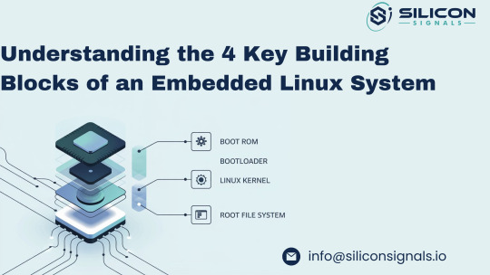
Each component plays a specific role in bringing the system to life, step by step. Here's a simple breakdown of the four essential parts of an embedded Linux system:
1. 🧠 Boot ROM – The Starting Point Inside the SoC
The Boot ROM is the very first code that runs when you power on your embedded device. It’s stored in read-only memory directly inside the System-on-Chip (SoC) and is similar to the BIOS on a standard computer. Although it's locked and can't be changed, it can react to external configurations (like boot pins) to decide where to load the next stage from – such as an SD card, eMMC, NAND flash, or even over UART/serial.
Some Boot ROMs also support secure boot by only allowing signed software to load next, adding a strong layer of security to the embedded system.
2. 🚀 Bootloader – Initializing the Hardware and Loading the Kernel
After the Boot ROM finishes its job, it passes control to the Bootloader. In many cases, the bootloader itself runs in two steps:
First stage: Prepares the system by initializing the RAM (since it's not ready right after power-up).
Second stage: Loads the Linux kernel from a chosen storage device or over a network (useful during development via TFTP).
Modern bootloaders also include features to:
Flash firmware or kernels onto memory devices like NAND or eMMC,
Test hardware components like I2C/SPI, RAM, and others,
Run Power-On Self-Tests (POST) to ensure system stability before launching the OS.
Popular bootloaders like U-Boot are often used in embedded Linux development for their flexibility and wide hardware support.
3. 🧩 Linux Kernel – The Core of the Operating System
The Linux Kernel is the brain of the system and is responsible for:
Talking to the hardware (drivers for peripherals),
Handling system tasks like scheduling and memory management,
Creating a stable environment for your applications to run.
It acts as the bridge between the hardware layer and the user space, making it possible to develop portable embedded applications that don’t rely on the specifics of the underlying board.
4. 📁 Root File System – The Application Playground
Once the kernel is up and running, its next task is to mount the root file system — the place where all applications, scripts, and shared libraries live.
Creating this from scratch is complex due to package dependencies and compatibility issues. That’s why tools like Buildroot, Yocto Project, or OpenEmbedded are used to automatically build and manage the root filesystem.
These tools help embedded developers customize and maintain a lightweight and reliable file system tailored to their device, ensuring consistency and performance.
Need Help Building Your Embedded Linux Solution?
At Silicon Signals, we specialize in custom embedded Linux development, including board bring-up, device driver integration, Android BSPs, secure boot implementation, and real-time optimizations.
Whether you're working on a new product or looking to optimize an existing one, our team can help you accelerate development and reduce risk.
📩 Contact us today to discuss how we can bring your embedded system to life. 🌐 Visit: www.siliconsignals.io ✉️ Email: [email protected]
#embeddedtechnology#embeddedsoftware#embeddedsystems#linux kernel#linuxdebugging#iot development services#iotsolutions
0 notes
Text
Building Custom HomeKit Devices

Have you ever caught yourself thinking, “I wish there was a HomeKit device that could do this…”? Yeah, same here. For me, it was wishing my washer-dryer could send a notification when the laundry’s done. See, it’s out in the yard—so if you’re chilling in the living room with the TV on, you’d never hear the washing machine’s faint beep of completion.
Luckily, I had a few ESP32s and sensors collecting dust in a drawer, so I thought: Why not build one myself? With a little help from AI, of course. I’ve been bouncing between Gemini 2.5 Pro, Grok, and ChatGPT, and they’ve been surprisingly great sidekicks. Sure, I could’ve sat down and studied all the libraries and frameworks properly—it might’ve taken me a couple of days tops (I’ve been around the programming and electronics block a few times). But thanks to AI, I hacked together a working prototype in just a few hours.
Now, this isn’t a tutorial—that’s coming soon once I’ve fine-tuned everything and properly tested my DIY HomeKit setup. This is more of a quick peek behind the curtain. A little show and tell.


For the build, I used an ESP32-S3 WROOM-1 (N16R8) and an MPU6050 3-axis accelerometer. Total cost? Around 7 bucks. Hooking up the sensor via I2C was simple enough. When any of the AIs got confused or hit a wall, I just tag-teamed between them until I got what I needed.
And here’s the result after just a few hours of tinkering—Apple’s Home app picked up my custom HomeKit device without a hitch. The best part? Seeing “ChrisTan Workshop” proudly listed as the manufacturer. Cracked me up. Nothing like a bit of DIY flair baked right into the Home app!


Here’s a quick rundown of how the magic works: the MPU6050 accelerometer monitors for vibrations. If it detects continuous movement for more than 20 seconds, we assume the washing machine is doing its thing and mark it as “running.” Once it stays still for over 3 minutes, we take that as a sign that the laundry’s done. These timings—and a few other parameters—are all configurable. I’m still fine-tuning them to match the quirks of my Electrolux washer dryer.
One of the trickier parts (and where all the AIs struggled a bit) was figuring out how to send a proper HomeKit notification. After some back-and-forth, we found a clever workaround: register the device as a doorbell. That way, when the laundry finishes, my HomePod mini chimes and a notification pops up like someone’s at the door. Not exactly elegant, but hey—it works! I just wish HomeKit gave us more flexibility with custom notifications, but I get it… Apple’s probably trying to prevent spammy alerts from rogue accessories.

That’s it for now. Eventually, I want to make this whole thing easily user-configurable—no coding required. But for the moment, a few parts are still hard-coded under the hood.
0 notes
Text
A Comprehensive Guide to Firmware Development

In the world of embedded systems and smart devices, firmware plays a critical role in enabling hardware to function effectively. Whether you're developing IoT devices, automotive systems, or industrial machinery, firmware development is the backbone that bridges hardware and software.
In this blog post, we’ll explore what firmware is, its importance, the development process, tools used, and best practices to ensure efficient and secure firmware solutions.
What is Firmware?
Firmware is a specialized type of software that provides low-level control for a device's specific hardware. Unlike regular software applications, firmware is tightly coupled with the hardware and is often stored in non-volatile memory such as ROM, EEPROM, or flash memory.
Examples of devices with firmware include:
Smartphones
Routers
Smart TVs
Medical devices
Automotive control units (ECUs)
Why is Firmware Important?
Firmware is essential because it:
Controls hardware operations: Without firmware, the hardware components of a device would be non-functional.
Ensures device functionality: It manages startup routines, I/O operations, sensor integration, and communication protocols.
Supports software-hardware integration: Firmware acts as a middle layer, allowing high-level software applications to interact with low-level hardware components.
Enables updates: Firmware can often be updated to fix bugs, enhance performance, or add features.
The Firmware Development Process
1. Requirements Gathering
Understanding the hardware specifications and the device’s purpose is crucial. Developers need to gather requirements from both hardware engineers and end users.
2. Architecture Design
This involves deciding on the architecture and communication protocols (e.g., I2C, SPI, UART), memory usage, and timing constraints.
3. Choosing a Development Platform
Most firmware is written in C or C++ due to their efficiency and hardware-level access. You’ll also need:
Microcontroller/microprocessor datasheets
Board Support Packages (BSPs)
RTOS (Real-Time Operating System), if required
4. Coding and Integration
Firmware code is written to interface directly with hardware. This includes writing drivers for peripherals (LEDs, sensors, motors) and managing power consumption, timing, and interrupts.
5. Testing and Debugging
Testing includes:
Unit testing
Hardware-in-the-loop (HIL) testing
Simulation and emulation tools
Debugging tools such as JTAG and SWD are used to step through code and analyze performance.
6. Deployment
Once tested, firmware is compiled and flashed onto the device using programmers or over-the-air (OTA) update mechanisms.
Tools Used in Firmware Development
Integrated Development Environments (IDEs): Keil µVision, MPLAB X, STM32CubeIDE
Compilers and Toolchains: GCC, IAR Embedded Workbench
Debuggers/Programmers: JTAG, ST-LINK, AVR ISP
Version Control Systems: Git
Simulators/Emulators: QEMU, Proteus
Best Practices for Firmware Development
Write modular and reusable code
Follow coding standards (e.g., MISRA C for safety-critical systems)
Optimize for memory and power consumption
Document thoroughly for maintainability
Implement fail-safes and watchdog timers
Secure your firmware (e.g., with encryption and secure boot loaders)
Plan for firmware updates with mechanisms like OTA updates
0 notes
Text
Understanding the Role of a Pressure Transducer in Modern Industries
Introduction
A pressure transducer is a critical device used across various industries to measure and convert pressure into an electrical signal. These instruments play a vital role in ensuring system efficiency, safety, and accuracy in applications ranging from automotive to aerospace. This article explores the working principle, types, applications, and advantages of pressure transducers, providing a comprehensive understanding of their significance.
What Is a Pressure Transducer?
A pressure transducer, also known as a pressure sensor, is a device that detects pressure and converts it into an analog or digital electrical signal. The output signal can be used for monitoring, control, or data recording purposes. These devices are essential in environments where precise pressure measurement is crucial for operational success.
How Does a Pressure Transducer Work?
The working principle of a pressure transducer involves several key components:
Sensing Element: Detects the applied pressure (e.g., diaphragm, piezoelectric crystal).
Transduction Mechanism: Converts the mechanical pressure into an electrical signal (e.g., strain gauge, capacitive element).
Signal Conditioning Circuitry: Amplifies and processes the signal for accurate output.
Output Interface: Delivers the signal in a usable format (e.g., 4-20mA, 0-10V, digital protocols like I2C or SPI).
When pressure is applied, the sensing element deforms, causing a change in resistance, capacitance, or voltage, which is then converted into a measurable signal.
Types of Pressure Transducers
Different applications require specific types of pressure transducers, each designed for unique operational conditions.
1. Strain Gauge Pressure Transducers
Uses a strain-sensitive element bonded to a diaphragm.
Pressure causes deformation, altering electrical resistance.
Common in industrial and automotive applications.
2. Capacitive Pressure Transducers
Measures changes in capacitance due to diaphragm movement.
Highly accurate and suitable for low-pressure applications.
3. Piezoelectric Pressure Transducers
Utilizes piezoelectric materials that generate voltage under pressure.
Ideal for dynamic pressure measurements in aerospace and defense.
4. Optical Pressure Transducers
Uses fiber-optic technology to detect pressure-induced changes in light properties.
Immune to electromagnetic interference, making them useful in harsh environments.
Key Applications of Pressure Transducers
Pressure transducers are widely used across multiple industries due to their versatility and reliability.
1. Industrial Automation
Monitors hydraulic and pneumatic systems.
Ensures safe operation of machinery by detecting pressure anomalies.
2. Automotive Industry
Measures fuel, oil, and tire pressure for optimal vehicle performance.
Used in engine management and braking systems.
3. Medical Equipment
Critical in ventilators, blood pressure monitors, and dialysis machines.
Ensures patient safety by providing accurate pressure readings.
4. Aerospace & Defense
Monitors cabin pressure, fuel systems, and hydraulic actuators.
Essential for flight safety and performance optimization.
5. Oil & Gas Industry
Used in drilling, pipeline monitoring, and refinery processes.
Detects pressure changes to prevent leaks and equipment failure.
Advantages of Using Pressure Transducers
The adoption of pressure transducers offers numerous benefits, including:
High Accuracy: Provides precise measurements for critical applications.
Durability: Designed to withstand harsh environments (e.g., extreme temperatures, corrosive media).
Versatility: Available in various types to suit different industrial needs.
Real-Time Monitoring: Enables immediate detection of pressure fluctuations.
Compact Design: Fits into tight spaces without compromising performance.
Choosing the Right Pressure Transducer
Selecting the appropriate pressure transducer depends on several factors:
Pressure Range: Ensure the device covers the required measurement range.
Output Signal: Match the output (analog, digital) with the system requirements.
Environmental Conditions: Consider temperature, humidity, and exposure to chemicals.
Accuracy & Resolution: Higher precision is needed for critical applications.
Installation Requirements: Check compatibility with mounting and connection setups.
Maintenance and Calibration
To ensure long-term reliability, pressure transducers require regular maintenance:
Periodic Calibration: Ensures measurement accuracy over time.
Cleaning & Inspection: Prevents contamination and mechanical wear.
Signal Verification: Confirms the output remains consistent with expected values.
Future Trends in Pressure Transducer Technology
Advancements in sensor technology continue to enhance pressure transducer capabilities:
Miniaturization: Smaller, more efficient designs for portable and IoT applications.
Wireless Connectivity: Enables remote monitoring and data logging.
Smart Sensors: Integration with AI for predictive maintenance and diagnostics.
Improved Materials: Enhanced durability for extreme environments.
Conclusion
The pressure transducer is an indispensable tool in modern industries, providing accurate and reliable pressure measurements for diverse applications. Understanding its working principles, types, and selection criteria ensures optimal performance in any operational environment. As technology evolves, these devices will continue to play a pivotal role in automation, safety, and efficiency across multiple sectors.
By leveraging the right pressure transducer, industries can achieve greater precision, reduce downtime, and enhance overall system performance. Whether in manufacturing, healthcare, or aerospace, these sensors remain a cornerstone of pressure measurement technology.

1 note
·
View note
Text
What are the main communication protocols in embedded systems?
Embedded systems rely on various communication protocols to enable efficient data transfer between components, microcontrollers, sensors, and external devices. These protocols can be broadly categorized into serial, parallel, wired, and wireless communication protocols.
UART (Universal Asynchronous Receiver-Transmitter) – A widely used serial communication protocol that facilitates full-duplex data exchange between embedded devices. It requires minimal hardware and is commonly used in debugging and low-speed data transfer applications.
SPI (Serial Peripheral Interface) – A high-speed, full-duplex protocol used for short-distance communication between a microcontroller and peripherals such as sensors, displays, and memory devices. It follows a master-slave architecture and is widely used in real-time embedded applications.
I2C (Inter-Integrated Circuit) – A multi-slave, half-duplex serial communication protocol designed for communication between multiple ICs using only two wires: SDA (data line) and SCL (clock line). It is highly efficient for low-speed applications and is commonly used in sensor integration.
CAN (Controller Area Network) – A robust, message-based protocol widely used in automotive and industrial applications. CAN allows multiple nodes to communicate efficiently without requiring a host computer. It ensures data integrity using error detection and correction mechanisms.
Ethernet – A widely adopted wired communication protocol that enables high-speed data transfer in embedded applications, especially in industrial automation and IoT systems. It supports networking capabilities for remote monitoring and control.
Bluetooth & Wi-Fi – These wireless protocols are essential for modern embedded systems, enabling connectivity in consumer electronics, IoT devices, and smart home applications. Bluetooth is preferred for short-range, low-power communication, while Wi-Fi offers high-speed data exchange over long distances.
Understanding these protocols is crucial for designing efficient embedded solutions. If you want to gain hands-on experience and expertise in these protocols, consider enrolling in an embedded system certification course.
0 notes
Text

BU9796 prototype finally comes to light ✨🔧🖥️
We covered the BU9796 a loooooooooong time ago on the Great Search while looking for an I2C LCD segment driver ...
youtube
but sadly, we never got around to making that breakout board. Til' now! This one features the FS series of the chip, which has some more segments: in this board, we expose 4 common and 18 segments to keep the board from getting too big. This chip runs at 3V or 5V, so it should be easy to use with any device. We still need to figure out what VLCD connects to - some parts of the datasheet say VDD, and some say VSS, so we left a jumper on the back. That way, we can connect it correctly when we are more awake. Stemma QT makes this a plug-and-play driver for just about any micro! Coming soon…
#adafruit#BU9796#prototype#i2c#lcd#hardwaredesign#electronics#makercommunity#techinnovation#engineering#diyelectronics#newrelease#devboard#microcontrollers#stemmaqt#Youtube
10 notes
·
View notes
Text
What are the key components of an embedded system?
Key Components of an Embedded System
An embedded system is a specialized computing system designed to perform dedicated tasks within a larger system. It is typically built to be highly efficient, reliable, and optimized for specific functions. Here are the key components of an embedded system:
1. Microcontroller/Microprocessor: The central unit of an embedded system, the microcontroller (or microprocessor), processes data and executes instructions. It typically includes a CPU, memory, and input/output interfaces, all integrated on a single chip. The microcontroller determines the system's speed, power consumption, and functionality.
2. Memory: Embedded systems often use different types of memory, such as ROM (Read-Only Memory) and RAM (Random Access Memory). ROM stores firmware and software, while RAM is used for temporary data storage during operations. Flash memory is also common, providing non-volatile storage for the system's data.
3. Sensors and Actuators: Sensors collect real-world data, such as temperature, pressure, or motion, while actuators convert signals into physical actions, like moving motors or turning on lights. These components allow embedded systems to interact with their environment and execute tasks based on input data.
4. Power Supply: Since embedded systems are often deployed in remote or portable environments, a reliable power supply is essential. Power management ensures that the system operates efficiently and can run on minimal power, extending battery life in portable applications.
5. Communication Interfaces: Embedded systems often require communication with other systems or networks. Communication interfaces such as UART, SPI, I2C, and Ethernet are used for data transfer between the embedded system and other devices.
6. Software/Firmware: The software or firmware controls the operation of the embedded system, instructing the hardware to perform specific tasks. It is usually optimized for performance and resource usage, ensuring the system works within its constraints.
To fully understand these components and their interaction, enrolling in an Embedded Systems Course can provide in-depth knowledge and hands-on experience in designing and programming embedded systems.
0 notes
Text
USB RTC for Raspberry Pi: The Best Way to Enhance Your Raspberry Pi's Time Accuracy

When it comes to building real-time applications with the Raspberry Pi, one of the most crucial components to ensure is timekeeping. A RTC (Real Time Clock) module provides the Raspberry Pi with a reliable source of time, even when the system is powered off. For those looking to achieve incredibly accurate timekeeping, a USB RTC for Raspberry Pi is a solution that combines the DS3231 RTC chip with a MCP2221 USB to I2C/UART converter is a perfect match.
In this blog post, we'll dive deep into what makes this USB RTC setup an ideal choice for your Raspberry Pi projects, and how it enhances accuracy, reliability, and ease of use.
What is USB RTC?
RTC is a device which is used for maintaining accurate time in the host’s system processor. With the Raspberry Pi, the internal clock relies on the system supply to track the accurate time and the main issue is when the Raspberry Pi is powered off, the clock resets. USB RTC is a solution for providing accurate timekeeping even when the Raspberry Pi is turned off or disconnected from the network. This setup allows users to easily add accurate timekeeping to their Raspberry Pi without using the GPIO pins.
The USB RTC is a device which comes with a strongly integrated DS3231 circuit that is used to consume less power and has an integrated temperature-compensated crystal oscillator. It has MCP2221, a USB-to-UART/I2C serial converter that provides USB connectivity, used in Raspberry Pi operations that contain USB, UART(Serial), GPIO, and I2C interfaces. This module can be used with Raspberry Pi, Windows, Linux or any other operating system.
Key Features & Specifications:
DS3231 RTC Circuit: The DS3231 provides a highly stable timekeeping function and includes a built-in temperature-compensated crystal oscillator (TCXO), which helps maintain accuracy across a wide temperature range.
Temperature-Compensated Crystal Oscillator (TCXO): This is a critical feature of the DS3231. TCXO compensates for temperature variations that could affect timekeeping accuracy. This ensures the RTC module performs well in a range of environments without the need for external temperature sensors.
Battery Backup (CR1220, 3V): The module uses a CR1220 coin-cell battery to maintain time even when the Raspberry Pi is powered off. This ensures your system's time is preserved even in the event of power failure or system reboot.
16-pin, 300-mil SO Package: The module comes in a compact and durable 16-pin, 300-mil SO (Small Outline) package. This size makes it easy to integrate into your projects.
Automated Backup Power Supply: The onboard battery backup power supply ensures your RTC chip continues to run and track time even when the Raspberry Pi is turned off or disconnected from power.
Fast 400kHz I2C Interface: The RTC communicates with the Raspberry Pi using a 400kHz I2C interface, allowing fast and efficient data transfer. This is crucial for time-sensitive applications, as it minimizes any lag or delay when reading the time or setting the RTC.
MCP2221 USB to I2C/UART Converter: The MCP2221 is a USB-to-I2C and UART converter that makes it easy to connect the RTC to the Raspberry Pi via a USB port. This eliminates the need for GPIO pins, making it a plug-and-play solution for Raspberry Pi users.
USB 2.0 Compatibility: The module uses USB 2.0 for a fast and stable connection to the Raspberry Pi, offering plug-and-play functionality without requiring complicated wiring or software configuration.
Plug-and-play: The device is plug-and-play, with available drivers for various operating systems, including Linux, ensuring smooth integration with the Raspberry Pi.
High Accuracy: ±2ppm from 0°C to +40°C: Offers incredible timekeeping accuracy of ±2ppm (parts per million) between 0°C and +40°C. This means that, in a typical environment, the RTC will deviate by no more than 2 seconds per day—a level of precision ideal for most hobbyist and professional projects.
Extended Accuracy Range: ±3.5ppm from -40°C to +85°C: In more extreme conditions, such as outdoor or industrial applications, this module maintains an accuracy of ±3.5ppm in the temperature range of -40°C to +85°C. Whether you're working in a chilly warehouse or a hot outdoor environment, this module ensures your Raspberry Pi’s timekeeping remains precise.
Versatile Timekeeping: The module doesn’t just count seconds and minutes; it also tracks days, dates, months, and even the year with leap year compensation valid until the year 2100. This makes it perfect for long-term projects, as you can rely on the RTC to keep accurate time for many years to come.
Two Time-of-Day Alarms: With two independently programmable time-of-day alarms, this RTC module allows you to set scheduled events. Whether you need to trigger an action, send a notification, or turn on/off a device at specific times, the alarms make it easy to synchronize with your Raspberry Pi’s actions.
Programmable Square-Wave Output: The square-wave output feature allows you to generate periodic signals that can be used to sync other devices. Especially useful in projects that require precise timing for communications or measurements.
Use Cases:
Data logging: For applications like weather stations or scientific experiments, you need precise timestamps for each data point.
Embedded systems: For embedded systems that require time-based tasks (like alarms or scheduled events), the RTC ensures that the system runs on a stable, reliable time.
Low-power applications: The RTC ensures your Raspberry Pi can operate in low-power or battery-operated setups while maintaining the correct time.
IoT devices: When building IoT applications where devices may not always have a constant internet connection, having a local, accurate time source is essential.
Conclusion:
For projects that demand extremely accurate timekeeping, the combination of the DS3231 RTC chip and the MCP2221 USB to I2C/UART converter is an excellent solution. This setup not only provides highly accurate, temperature-compensated time tracking but also integrates seamlessly with the Raspberry Pi via a fast I2C interface.
Whether you're building a weather station, data logger, or any time-sensitive project, the DS3231 with MCP2221 ensures that your Raspberry Pi has reliable, battery-backed, and accurate timekeeping capabilities that won't be affected by power outages or system restarts.
#technology#rtc#innovation#tech#iot#raspberry pi#projects#iot applications#iotsolutions#usb rtc#real time projects
0 notes
Text
Android 14 on Toradex-TI-AM62 Verdin SoM + Dahlia Carrier Board
We are happy to inform you that our engineering team has successfully ported Android 14 onto the Dahlia Carrier Board and the Toradex Verdin AM62 System on Module (SoM), which is powered by Texas Instruments Sitara AM62x processors. Providing a fully functional, ready-to-use Android 14 environment with seamless integration of essential features like HDMI display, touch, Wi-Fi, Bluetooth, audio playback, and OTA updates, this project represents a significant milestone in improving embedded systems for a wide range of applications.

Why Android 14 on Verdin AM62 SoM?
The Verdin AM62 SoM provides the ideal balance between performance and energy efficiency thanks to its affordable yet robust architecture, which is powered by up to four Cortex-A53 cores and the heterogeneous Cortex-M4 for real-time tasks. This SoM is perfect for a variety of use cases, including medical applications, smart cities, industrial automation, and more, thanks to its extensive range of interfaces, which include Ethernet, USB, CAN FD, SPI, I2C, and MIPI camera. The Verdin AM62 SoM's capabilities are increased by Android 14, which offers improved connectivity, security, and performance. We have opened up a world of opportunities for developers who need to use modern operating systems in their embedded projects by successfully porting Android 14.
Key Features Implemented
Our team has gone the extra mile to make this port as user-friendly as possible, including:
Ready-to-Use Flash Image: We have created a simple flash image that uses an installer, so you can quickly install Android 14 on the Verdin AM62 SoM. Even for individuals with less Android porting experience, this makes the entire process easy and accessible.
Fully Working HDMI Display and Touch Support: The port offers a great interface for interactive applications by supporting HDMI displays with touchscreen capabilities.
Wi-Fi and Bluetooth Functionality: This port is perfect for connected IoT applications because we have made sure that wireless connectivity, including dual-band Wi-Fi and Bluetooth 5.2, is fully functional.
Audio and Video Playback: We have seamlessly incorporated both Bluetooth and standard audio playback into the system, offering a dependable media experience. Applications that use a lot of multimedia can benefit from the platform's optimized video playback.
OTA Updates via Update Engine: Using Android's Update Engine to integrate Over-the-Air (OTA) updates is one of this port's most notable features. This implies that devices using this system can get updates remotely, guaranteeing that they stay safe and current without the need for anyone's involvement.
Simplifying Embedded Android Development
As a product design and development partner for Toradex, we’ve leveraged the company's extensive ecosystem, including the Torizon platform for IoT device management. With Torizon’s built-in OTA, remote access, and monitoring capabilities, this Android 14 port makes it easier for developers to manage devices in the field.
The Advantages for Embedded Engineers
This port unlocks opportunities for embedded engineers and developers to explore Android's robust ecosystem in industrial, medical, and IoT applications. The Verdin AM62 SoM’s low-power operation and rich set of interfaces make it highly adaptable to various hardware requirements, while the simplicity of Android's application layer allows rapid development and deployment.
Conclusion
Porting Android 14 on the Toradex Verdin AM62 SoM is a testament to our expertise in embedded systems development. By offering an Android environment that is fully operational and ready for use, we have established a strong foundation for upcoming advancements. Our port of Android 14 makes it easier to develop solutions for connected systems, smart devices, or industrial automation, allowing you to concentrate on what really matters—creating the next generation of intelligent devices.
Are you interested in using Android 14 for your project on the Verdin AM62 SoM? To find out how we can help you on your embedded systems development journey, get in contact with us!
0 notes
Text
How to Learn Embedded Systems: A Comprehensive Guide
Embedded systems are integral to countless applications, from consumer electronics to industrial automation. Understanding how to learn embedded systems can open up a world of opportunities in various fields, including robotics, automotive, healthcare, and IoT. Here’s a structured approach to mastering embedded systems.

1. Understanding the Basics
Start with the fundamentals of embedded systems. Familiarize yourself with key concepts such as:
What are Embedded Systems?
Embedded systems are specialized computing systems that perform dedicated functions within larger mechanical or electrical systems. Unlike general-purpose computers, they are designed to execute specific tasks with high reliability.
Components of Embedded Systems:
Microcontrollers and Microprocessors: Understand the difference between the two. Microcontrollers are compact integrated circuits designed to govern a specific operation in an embedded system, while microprocessors are the central unit of a computer that performs calculations and logic operations.
Memory: Learn about different types of memory (RAM, ROM, Flash) used in embedded systems.
Input/Output Devices: Familiarize yourself with sensors, actuators, and communication interfaces (UART, SPI, I2C).
2. Choose Your Learning Resources
Select resources that match your learning style. Here are some options:
Books:
"Embedded Systems: Introduction to the MSP432 Microcontroller" by Jonathan Valvano
"Programming Embedded Systems in C and C++" by Michael Barr
Online Courses:
Platforms like Coursera, Udemy, and edX offer courses in embedded systems. Look for those that cover microcontrollers, programming, and interfacing.
YouTube Channels:
Channels like "The DIY Life" and "NPTEL" provide practical insights and tutorials on embedded systems.
3. Get Hands-On Experience
Theory is essential, but hands-on practice is crucial for mastering embedded systems. Consider the following:
Development Boards:
Start with popular development boards like Arduino, Raspberry Pi, or ESP32. These platforms are beginner-friendly and have extensive community support.
Build Projects:
Create simple projects like LED blinkers, temperature sensors, or motor controls. Gradually move to more complex projects like home automation systems or robotic applications.
Use Simulation Tools:
Familiarize yourself with simulation tools like Proteus or MATLAB/Simulink for testing your designs virtually.
4. Learn Programming Languages
Embedded systems often require programming skills. Focus on:
C/C++ Programming:
C is the most commonly used language for embedded systems due to its efficiency and control over hardware. Learn the syntax, data structures, and memory management.
Assembly Language:
Understanding assembly language can provide deeper insights into how microcontrollers operate.
5. Explore Real-Time Operating Systems (RTOS)
Many embedded systems require multitasking and real-time performance. Learning about RTOS concepts can be beneficial:
Understand the Basics:
Familiarize yourself with the concepts of task scheduling, inter-task communication, and resource management.
Hands-On with RTOS:
Try using an RTOS like FreeRTOS or Zephyr on your development board. Implement multitasking projects to get practical experience.
6. Join Online Communities
Engaging with fellow learners and professionals can enhance your learning experience:
Forums and Discussion Groups:
Platforms like Stack Overflow, Reddit, and specialized forums (e.g., Embedded Related) are great for seeking help and sharing knowledge.
Attend Workshops and Webinars:
Participate in online workshops or local meetups to learn from experts and network with peers.
7. Stay Updated with Industry Trends
The field of embedded systems is constantly evolving. Keep yourself updated with the latest trends and technologies:
Follow Industry News:
Subscribe to blogs, newsletters, and magazines related to embedded systems.
Participate in Hackathons:
Engage in hackathons or coding competitions focused on embedded systems to test your skills and learn from others.
Conclusion
Learning embedded systems requires a mix of theoretical knowledge and practical experience. By following this structured approach—starting from the basics, choosing the right resources, getting hands-on experience, and staying engaged with the community—you can build a strong foundation in embedded systems. Whether you aim to work in robotics, IoT, or automation, mastering embedded systems can significantly enhance your career prospects. Start your journey today, and embrace the exciting world of embedded systems!
0 notes
Text
5 Insider Tips for Mastering IoT Architecture in Embedded Systems

As we navigate the complexities of IoT architecture in embedded systems, we’ve identified five crucial tips that can significantly streamline our approach. By integrating security from the very beginning and embracing collaborative methods, we set a solid foundation for success. We’ll also need to emphasize comprehensive testing and ensure scalability for future growth. But what’s the one element that ties all these strategies together? Let’s explore how these insights can elevate our projects and lead to more effective outcomes.
Understand Hardware and Software Interplay

In mastering IoT architecture within embedded systems, we must recognize the crucial interplay between hardware and software. Understanding this relationship is essential for developing efficient, reliable systems.
Embedded systems typically consist of a microcontroller unit (MCU), which acts as the brain, supported by components like memory, timers, and communication ports. The architecture is layered, with physical hardware at the base, system software managing tasks, and application software tailored for specific functions.
Effective communication protocols, such as UART, SPI, and I2C, are vital for interaction between these layers, allowing data to flow seamlessly. We need to ensure that our hardware supports the software requirements, optimizing performance while managing resources.
Real-time operating systems (RTOS) play a key role in task management, particularly for time-sensitive applications.
Prioritize Security From the Start

Prioritizing security from the start is crucial for the success of IoT systems. We need to adopt a security-by-design approach that integrates robust measures early in the development cycle.
As we all know, successful IoT products tend to attract malicious attackers, making it essential to protect our assets from various vulnerabilities. By focusing on security from the beginning, we can better safeguard our devices and user data.
Here are some key aspects to consider:
Understand Attack Surfaces: Every interaction point—from devices to servers—poses risks, so we must address vulnerabilities across the entire system.
Implement Anti-Tampering Techniques: Employ methods to detect and respond to potential attacks, ensuring the integrity of our devices and data.
Ensure Communication Security: Utilize secure protocols like TLS to protect data in transit and maintain trusted connections.
Embrace Agile Collaboration Methods

Agile collaboration methods can transform how we approach IoT architecture in embedded systems. By adopting Agile methodologies, we create an environment that emphasizes flexibility and responsiveness. Instead of following rigid plans, we break projects into manageable increments, allowing us to deliver working software frequently. This iterative approach fosters collaboration among cross-functional teams, ensuring everyone is aligned and contributing to the project’s success.
We should consider frameworks like Scrum or Kanban, which promote continuous improvement and encourage adaptive planning. Daily stand-up meetings keep us focused and aligned, while regular sprint reviews help us assess our progress and make necessary adjustments. This method not only enhances product quality but also boosts team morale and productivity.
While we embrace Agile, we must also be aware of the challenges specific to embedded systems. Real-time constraints and regulatory requirements can complicate adoption. However, by investing in specialized tools and maintaining effective communication, we can overcome these hurdles.
Ultimately, Agile collaboration enables us to prioritize high-value features and adapt to evolving stakeholder needs, leading to a more successful IoT architecture in our embedded systems.
Focus on Testing and Validation

Effective collaboration sets the stage for robust testing and validation in IoT architecture.
As we dive into this crucial phase, we must understand that IoT devices present unique challenges. Our testing strategies need to encompass both hardware and software elements to ensure seamless functionality.
Here are three key focus areas for our testing efforts:
Integrated Testing Strategies: We should prioritize testing components like sensors, applications, and network communication, ensuring they work together before deployment.
Test Automation: Given the scale and complexity of IoT environments, automating our testing processes will save time and increase reliability.
Security Testing: Validating security mechanisms is non-negotiable. We must verify access controls, authentication, and encryption to protect our devices from vulnerabilities.
Ensure Scalability and Maintainability

Recognizing the critical role of scalability and maintainability in IoT architecture, we must design our systems to adapt seamlessly as demands grow. Scalability is essential for transitioning from prototype to production, much like how e-commerce platforms scale during peak times. To achieve this, we need a robust infrastructure that includes cloud solutions and versatile hardware capable of operating across various networks.
We can’t overlook the integration of hardware, software, and connectivity right from the start. If we ignore these aspects, we risk facing a staggering 75% failure rate seen in many IoT projects due to inadequate planning. Collaborating with expert providers can simplify the scaling process, allowing us to leverage IoT Platform-as-a-Service solutions to enhance our scalability.
Security is another critical factor; as we scale, we must implement ongoing security measures and effective device management strategies. This includes ensuring over-the-air updates and maintaining compliance with necessary certifications.
Frequently Asked Questions
What Specific Tools Can Help With Iot Architecture Design?
When we design IoT architecture, we can leverage tools like AWS IoT, Azure IoT Hub, and MQTT for communication. Using these tools helps us streamline development, enhance scalability, and ensure secure data handling in our projects.
How Do I Choose the Right Communication Protocol for My Project?
When choosing the right communication protocol for our project, we should consider factors like data rate, range, power consumption, and scalability. Let’s evaluate our specific requirements to ensure we select the most suitable option.
What Are Common Pitfalls in Iot Development to Avoid?
In our IoT development journey, we must avoid common pitfalls like neglecting security, overlooking scalability, and underestimating testing. By being proactive and prioritizing these aspects, we can create robust, efficient systems together.
How Can I Effectively Manage Iot Device Updates?
To effectively manage IoT device updates, we should implement automated systems that streamline the process. By scheduling regular updates and testing them thoroughly, we can enhance security and performance while minimizing downtime for our users.
What Metrics Should I Track for Iot System Performance?
To track IoT system performance, we should monitor metrics like latency, throughput, device uptime, and error rates. These indicators help us identify bottlenecks and enhance user experience, ensuring our systems remain efficient and reliable.
Conclusion
In conclusion, mastering IoT architecture in embedded systems requires us to integrate key strategies from the outset. By understanding the interplay between hardware and software, prioritizing security, and embracing agile methods, we can build robust systems. Let’s not forget the importance of thorough testing and validation, as well as planning for scalability and maintainability. By following these insider tips, we can create innovative and secure IoT solutions that stand the test of time.
Sign up for free courses here.
Visit Zekatix for more information.
#artificial intelligence#courses#edtech company#embedded systems#academics#nanotechnology#embeded#online courses#robotics#zekatix
0 notes