#high voltage termination
Explore tagged Tumblr posts
Visit Tumblr Blog
Explore Tumblr blogs with no restrictions, modern design and the best experience.
Last Seen Tumblr Blogs


Fun Fact
Women make up for the other 50% of Tumblr’s audience.
Text

diagram of the Terrible Critters . because i recently had to explain how the hell the hv swap worked & it was harder than it had to be
#wasn’t sure if i wanted to post this or not but#what evar#peachphernaliart#chonny jash#chonnys charming chaos compendium#cccc#cj heart#cccc heart#cj mind#cccc mind#cj soul#cccc soul#cj hms#high voltage hms#hms au#hv!heart#signal#hv!mind#circuit#hv!soul#terminal#may be expanded once we figure out the Reverse swap au …
378 notes
·
View notes
Text
@sunnydayaoe 's High Voltage au HMS !!


These guys have taken hold of me and I can't escape they're so cool, I love this au!!!
I've done a couple more sketches of the guys which I'll post in a minute too!
#chonny jash fanart#chonny jash#cccc#cccc hms#chonnys charming chaos compendium#high voltage#heart mind and soul#high voltage hms#HV!art#circuit#signal#terminal#as long as he can hold a pen he is a threat
88 notes
·
View notes
Text

While I’m still working on other art (and those asks ya’ll so lovingly sent in) take an image of if Stratos swapped with @peachphernalia ‘s character “Terminal” !
This is also a representation of whenever people tell me about their character lore and I’m just sat there like QAQ LMAO
#my art#art#character art#artists on tumblr#ocs#chonnys charming chaos compendium#chonny jash#digital art#cccc oc#high voltage hms#blood n ichor#terminal#stratos#coela art
60 notes
·
View notes
Text
Building Resilient Electrical Systems: The Combined Power of Heat Shrink Straight Through Joints, Indoor Terminations, and High Voltage Tape
In the intricate and demanding world of electrical infrastructure, the reliability and longevity of connections are paramount. From extensive outdoor cable runs to the delicate circuitry within indoor environments, the seamless flow of electricity hinges on robust and secure components. Heat Shrink Straight Through Joints, Heat Shrink Indoor Terminations, and High Voltage Tape are essential technologies that contribute significantly to the safety, reliability, and longevity of electrical systems. Each serves a distinct purpose, yet they work in synergy to fortify electrical infrastructure against environmental stresses, mechanical forces, and electrical hazards.
Heat Shrink Straight Through Joints: Ensuring Uninterrupted Power Flow
In the vast network of electrical cables that transmit power across distances, the need for reliable splicing is undeniable. Whether for extending cable runs, repairing damage, or connecting to equipment, the integrity of cable joints is crucial. Traditional splicing methods often fall short, leaving connections vulnerable to environmental factors, mechanical stress, and electrical faults.
Heat Shrink Straight Through Joints offer a superior solution. By utilizing heat-shrinkable tubing that contracts upon heating, these joints create a tight, environmentally sealed connection. This seal acts as a formidable barrier against moisture, dust, chemicals, and other contaminants, preventing corrosion and degradation. The mechanical strength of the shrunk tubing provides excellent resistance to vibration, impact, and tensile forces, ensuring the joint remains secure even in demanding environments.
Furthermore, the electrical insulation properties of the heat-shrink material prevent short circuits and maintain the integrity of the electrical circuit. This combination of environmental protection, mechanical strength, and electrical insulation makes Heat Shrink Straight Through Joints essential for a wide range of applications, from underground and overhead power distribution to industrial and renewable energy installations.
Heat Shrink Indoor Terminations: Securing Connections in Enclosed Environments
While Heat Shrink Straight Through Joints address cable splicing in outdoor and general applications, Heat Shrink Indoor Terminations cater to the crucial task of connecting cables to electrical equipment within buildings and enclosed spaces. These terminations provide a secure and insulated interface between cables and devices like switchgear, transformers, and motors.
The compact design of heat shrink indoor terminations is particularly advantageous in environments where space is often limited. The heat-shrinkable components, including stress control tubes, insulation tubes, and sealing tubes, create a sealed and insulated connection that protects against electrical faults and environmental hazards.
Proper stress control is crucial in indoor terminations to prevent electrical breakdown at the cable's insulation cut-off point. Heat shrink materials are engineered to manage electrical stress, ensuring reliable performance over the long term. The installation process, while requiring precision, is relatively straightforward, contributing to efficiency and reduced downtime.
Heat Shrink Indoor Terminations play a vital role in ensuring the safety and reliability of electrical installations in substations, industrial plants, commercial buildings, and data centers. By providing a secure and insulated interface, they contribute to the seamless operation of critical electrical equipment.
High Voltage Tape: Versatile Insulation and Protection
Complementing the robust solutions offered by heat shrink technologies, High Voltage Tape provides a versatile tool for insulation, protection, and repair. This specialized tape, designed for high-voltage applications, offers exceptional dielectric strength and environmental resistance.
High Voltage Tape is used for a variety of tasks, including insulating cable splices and terminations, repairing damaged insulation, and providing additional protection in critical areas. Its ability to withstand high voltages and resist moisture and chemicals makes it an essential component in electrical maintenance and repair.
The tape's flexibility and conformability allow it to be easily applied to irregular shapes and surfaces, ensuring a tight and reliable insulation barrier. Its self-fusing properties create a seamless, void-free insulation layer that enhances its performance.
The Integrated System: A Holistic Approach to Electrical Integrity
Heat Shrink Straight Through Joints, Heat Shrink Indoor Terminations, and High Voltage Tape, when used in conjunction, provide a comprehensive approach to ensuring electrical integrity. Each technology plays a crucial role in its respective domain, yet they all contribute to the overarching goal of creating reliable and safe electrical connections.
By combining the robust splicing capabilities of Heat Shrink Straight Through Joints, the secure indoor termination solutions of Heat Shrink Indoor Terminations, and the versatile protection offered by High Voltage Tape, engineers and technicians can build electrical systems that are resilient, efficient, and long-lasting.
In a world increasingly reliant on electricity, the importance of reliable connections cannot be overstated. These technologies, when properly applied, contribute to the seamless operation of critical infrastructure, minimizing downtime, reducing maintenance costs, and ensuring the safety of personnel and equipment. The integration of these products provides a robust and dependable electrical system.
0 notes
Text
https://www.futureelectronics.com/p/interconnect--connectors-pcb--shunts-jumpers/5102tr-keystone-5046274
Jumper cap, jumper wire connector Jumper wire types, coaxial cable connector
0.02 in 0.5 mm Thick Copper (Silver Plated) 0.27 in 6.85 mm Long Jumper
#Keystone#5102TR#Connectors#PCB Shunts & Jumpers#Jumper cap#jumper wire connector Jumper wire types#coaxial cable connector#terminal jumpers#cables#high voltage jumper wire#high current jumper#solder bridge jumper#jumper wire#wire connector
0 notes
Text
Coaxial Load Terminations | High Voltage Products, GmbH
Our high-voltage resistive load unit manages pulse voltages up to 500 kV for short bursts (within 100 ns) without causing interference. It supports up to 250 repetitions per second in 10-pulse sequences. Optional features, like a calibrated current-viewing resistor or a D-dot probe, enhance current monitoring.
Know more!
0 notes
Text
https://www.futureelectronics.com/p/semiconductors--discretes--transistors--mosfets/re1c002untcl-rohm-3063706
Small Signal Mosfet, High power mosfet, mosfet terminals, mosfet as a switch
RE1C002UN Series 20 V 1.2 Ohm 200 mA Surface Mount Small Signal Mosfet - EMT-3F
#ROHM#RE1C002UNTCL#Transistors#Mosfets#Small Signal#High power#mosfet terminals#power transistor#Transistors Mosfets#power mosfet#mosfe get#mosfe swhich#power supply#High voltage mosfet#Mosfet module#P-Channel Mosfet
1 note
·
View note
Text
How do Pikachu produce electricity?

(This is a photo of my Pikachu, Eggnog, blending in with a bunch of plushies on my bed. Isn't she cute?)
Electric types are my specialty, so I thought a great way to start off this blog would be to get into the anatomy of electric organs in pokemon! It differs depending on the species, but its pretty conserved among electric mice.
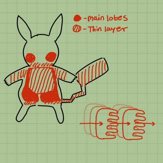
Much of Pikachu's body is made up of two dense electric organs in its body cavity. Most of the mass is in the lower half of the body, separated from the organs by a relatively thick layer of insulating fat. This is why Pikachu are heavier than you might expect for their size! These organs are made of layers of thousands of columns of cells called electrocytes arranged in series, with parallel layers separated by thin insulating tissue to prevent short circuiting. This enables them to efficiently build a high amount of current and voltage very quickly. In the chubbier parts of the arms, tail, and insulated from the organs in the rest of the body cavity are thinner layers of electrocytes to maximize electricity generation.
Interestingly, electrocytes are actually a type of modified muscle cell! Each cell is innervated by a nerve terminal where neurotransmitter release triggers an action potential similar to those in muscle cells and neurons.
The electric organs are beneath the muscle layer and separated by another layer of insulation to prevent seizing during the release of electricity. Insulated channels between the muscle layer allows the produced electricity to move past the muscle and escape through the skin. These channels can be opened and closed to direct electricity to different parts of the body for different moves (think Electro Ball!)
Pikachu fur differs from non-electric type furry pokemon in that it's actually composed of a mixture of several metals (primarily copper and zinc) coated in a thin layer of a protein similar to the chitin found in bug types. In this way, the fur acts more to conduct electricity than to insulate the pokemon against temperature loss. This makes temperature control a challenge for Pikachu, but the thick layers of fat insulation, metabolic heat from electricity production, and social huddling helps keep them warm.
You might've noticed that Pikachu's striking red electric sacs in its cheeks are completely hairless. This helps it directly conduct electricity in smaller amounts, like when communicating. These sacs are also the only electricity-generating organs in its head, and are thoroughly insulated to prevent any misfiring to the brain. This has the side effect of making its cheeks extra stretchy and squishy!
These electric sacs also differ from the main electric organs in that they have specialized battery glands that can store even more electricity. When Pikachu is asleep, they're able to "recharge" these glands similar to the process in rechargeable batteries, except with very minimal efficiency loss over its lifespan.
And there you have it! A basic run down of how Pikachu generates electricity. If you have any questions or comments, please feel free to let me know! And of course, if you have any corrections, please let me know as well! I'm pretty experienced with electric types but I'm also still just a student. :]
53 notes
·
View notes
Text

high voltage stuff . did you know they are so Unbelievably stupid . Affectionate
#peachphernaliart#might change how i draw circuit not very used to him yet#sorry Sorry#high voltage hms#hv!soul#terminal#hv!heart#signal#hv!mind#circuit#chonnys charming chaos compendium#chonny jash#cj hms#hms au#cccc soul#cccc heart#cccc mind#idk if i should maintag them .#do they Count
247 notes
·
View notes
Text
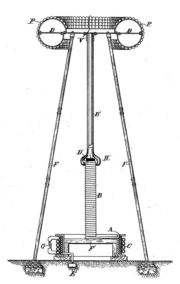
The Evolution of the Tesla Coil

Nikola Tesla invented the Tesla coil as part of his exploration into lighting, wireless power transmission, and radiofrequency experiments. He developed the coil to produce high-voltage, low current, high-frequency electricity. The Tesla coil consists of primary and secondary coils that are inductively coupled, and the circuit is designed to resonate at a specific frequency. This resonance enhances the efficiency of energy transfer between the coils, enabling the generation of high-voltage, high-frequency alternating current.
His first Tesla coil was a bipolar coil created around 1891, and was demonstrated before scientific institutes from 1891-1893. His patents reveal that they were essentially intended for light production using both high frequency and high voltage at the same time. He also mentions in his patents how he discovered that a single wire could be used to light a light bulb. Generally, light bulbs require two wires to operate – one for the positive (live or hot) and one for the negative (neutral). He also discarded wires completely lighting bulbs wirelessly. Tesla improved upon the bipolar coil over many years using them for gas engine ignition, wireless, ozone production, and to create undamped waves.
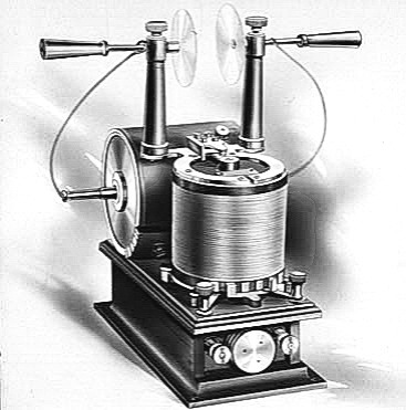
In 1893, Tesla developed the bifilar spiral coil, which is a type of coil wound with two parallel wires, known as bifilar winding. The wires are wound side by side in a spiral pattern, maintaining close proximity throughout the coil. It was built in an attempt to avoid the employment of condensers, which are expensive and difficult to maintain. The coils themselves were meant to accomplish the same ultimate object as the condensers.

In 1894, Tesla evolved his coil into a conical coil. A conical coil refers to a coil or winding in the shape of a cone. These coils were sometimes employed in his wireless power transmission experiments and other electrical investigations. The shape of the coil can influence its inductance, capacitance, and resonance properties, impacting its performance in different applications. This coil allowed Tesla to reach tensions of 1 million volts.
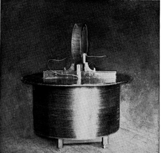
In 1897, Tesla developed the flat spiral coil, similar to his bifilar coil. This type of coil forms a flat, spiral pattern. The specific shape and dimensions of the coil can influence its inductance and other electrical properties. The main reason Tesla started using flat spiral coils was because they were relatively safe, since the highest potential terminal is at the center, and also because they better suppressed the sparks, which were essentially losses in the circuit, allowing him to achieve higher voltages:
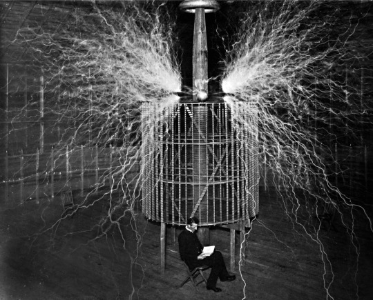
Another version of his coils was his Helical coil. A helical coil is a coil wound in the shape of a helix or spiral. The helical coil configuration is characterized by the wires being wound around a cylindrical form in a continuous spiral pattern. Tesla utilized helical coils throughout the late 1890s and in his Colorado Springs Experiments. The coils were used in his wireless transmission experiments, and he employed helical resonators to investigate the behavior of electromagnetic waves. The helical shape offers specific electrical properties and can influence the resonance and performance of the coil in certain applications.
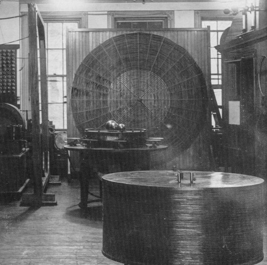
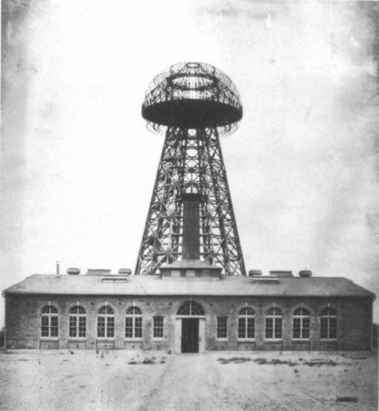
Finally, the Tesla coil would eventually evolve into his Magnifying Transmitter. Tesla designed it as part of his wireless power transmission experiments. The magnifying transmitter was intended to efficiently transmit electrical energy over long distances without the need for wires. The system involved a large coil, often called the magnifying transmitter coil, which could produce high-frequency, high-voltage electrical currents. Tesla believed that this technology could revolutionize global communication and provide a means for delivering electrical power wirelessly by using the earth itself as a conductor.
The magnifying transmitter would become his Wardenclyffe Tower. Unfortunately, Tesla ended up lacking the investments and funds to finish his work in its entirety. Some say he failed because his idea didn’t work, but that’s not true at all because his Colorado experiments proved that they did. In his head, the transmission of energy was a matter of engineering. If he had a machine that could send energy 20 miles, then he could build a machine that could send energy a thousand miles. As long as he understands the motive power, he could build a machine that will do all that he requires of it. He simply underestimated the cost of his system. His failures to finish his work would leave him with the public persona as being the mad scientist who had unrealistic ideas for the future.
Ultimately, Tesla would not realize his dream of providing humankind with cheap, unlimited energy in his lifetime; however, his legacy forever lives on through the incredibly impactful experiments, and the evolution of the Tesla Coil.
“Technical invention is akin to architecture and the experts must in time come to the same conclusions I have reached long ago. Sooner or later my power system will have to be adopted in its entirety and so far as I am concerned it is as good as done. If I were ever assailed by doubt of ultimate success I would dismiss it by remembering the words of that great philosopher, Lord Kelvin, who after witnessing some of my experiments said to me with tears in his eyes: ‘I am sure you will do it.’”--Nikola Tesla
#nikola tesla#science#history#electricity#invention#wireless#energy#power#Tesla coil#quotes#ahead of his time#ahead of our time
239 notes
·
View notes
Text

omg is that... another ethereal drawing?? LMAO Yes, yes it is. Unsurprisingly it's for @peachphernalia 's Terminal from High Voltage! As opposed to the usual flowy and soft colors for other characters I've done, Terminal is more punk and wears more spikes. There's also some religious symbolism with the character that I wanted to try and involve? BUT YEAH WE LOVE HIGH VOLTAGE IN THIS HOUSE LMAO
#my art#art#character art#artists on tumblr#chonnys charming chaos compendium#ocs#chonny jash#digital art#cccc oc#cj heart#hms#cccc fanart#high voltage hms
180 notes
·
View notes
Text


Signal and Terminal from the High voltage AU!!
Honestly everything bout this AU is super well thought-out and I know I've said it before but I absolutely love it
I hope you guys like the fanart :]
@high-voltage-archive
128 notes
·
View notes
Text
https://www.futureelectronics.com/p/interconnect--connectors-pcb--shunts-jumpers/5102tr-keystone-5046274
Jumper cap, jumper wire connector Jumper wire types, coaxial cable connector
0.02 in 0.5 mm Thick Copper (Silver Plated) 0.27 in 6.85 mm Long Jumper
#Keystone#5102TR#Connectors#PCB Shunts & Jumpers#Jumper cap#jumper wire connector Jumper wire types#coaxial cable connector#terminal jumpers#cables#high voltage jumper wire#high current jumper#solder bridge jumper#jumper wire#wire connector
1 note
·
View note
Text
On Bodging Silly Mistakes
After a few weeks of rest and working on non-homebrew-related projects since getting my 68030 stack running 8-user BASIC, I've circled back around to the project. My goal is to have it ready to exhibit for VCF Southwest 2025 in June.
The first thing to do when picking up an old project is to make sure it still works to begin with.
It did not.
The computer would start up, go through its boot process, and start the user programs. The supervisor terminal would accept and execute commands, but none of the user terminals would accept input.
I could tell the serial data was making it to the machine, because my 8-port serial card has indicator LEDs on the Transmit & Receive signals and they were working as expected. If I held down a key as the system booted, it would print that character a few times before stopping and then no longer accept any more data. So it really looked like the hardware was working. Nothing had changed in software so that wasn't likely to be the issue.
It reminded me of the problems I encountered with reading from disk when CPU cache was preventing the updated disk status bit from being read. The serial card supports asserting the CPU's Cache Inhibit signal, but perhaps that circuit wasn't functioning. There was no change with it connected or not. Time to break out the oscilloscope. The Cache Inhibit signal was always low — always asserted. Cache wasn't the problem because cache was effectively always disabled.
Out of ideas, it was time to break out the logic analyzer. The I/O Read & Write signals on the serial card were working as expected, and it was properly addressing the card & its individual ports. So next thing was to check was the actual data being read from the UARTs.
Letting the logic analyzer run and watching the data fly through, the problem finally made itself known — the UARTs were not setting bit 0 of the status byte to indicate that they had received data. The data was getting to the UART, it just wasn't acknowledged.
But why? And why did it work initially on restart and then stop? And why did it work without issue a few weeks ago? What is different?
What is different, indeed. I have made one change to the hardware since I last ran it — I added a proper watchdog/power-on-reset controller. If the power supply drops below 4.7 volts, it will reset the computer. The power supply I had been using was marginal and was getting caught by the watchdog, so I switched to a proper power PC supply.
So what's different since last time I ran the system is my reset circuit is more effective and the system voltage should be much more stable 5V.
And that's when I realized a mistake I made in the design for my 8-port serial card. The 68k reset signal is active-low and the 16C55x UART reset signal is active-high. I was trying to minimize part count, and didn't have an inverter for the reset signal, so I used what I had on hand — a buffer with an active-low enable signal.

Anyone well-versed in electronics may already see the problem.
When the CPU-RESET# signal is asserted (low), the buffer will set its output, IO-RESET to match its input, VCC (high). That's great, we get a high signal on the output whenever the CPU Reset signal is low.
Except ... what happens when the CPU Reset signal is not asserted? The buffer goes open-collector and doesn't pull the IO-RESET signal one way or the other; it's just left floating.
Floating signals are bad news for digital circuits. Their behavior is unpredictable and subject to environmental noise, power fluctuations, etc. For my IO-RESET signal to function properly, something needs to pull it low whenever the 74'125 buffer is not actively driving it high. A good-sized pull-down resistor should do the job just fine, so I dug through my stock and found a 3.65k surface-mount resistor and bodged it onto the back side of the board.

And sure enough, that fixed the problem!
It is possible that when I was running the system on that marginal power supply previously, the IO-RESET signal was able to stay just low enough to not trigger reset on the UARTs. Or it could have just been different environmental factors.
I'm glad I took the time to test the machine today, and I'm glad this bug came up. It's the kind of bug that could easily have come up when running in a new environment for the first time — such as on the show floor at VCFSW. Far better to run into a bug like this at home with access to all of the tools (and time) to figure it out.
Now that things are up and running again I can continue my testing and setup for VCFSW.
#homebrew computing#homebrew computer#vintage computing#motorola 68030#motorola 68k#mc68030#wrap030#vcfsw
16 notes
·
View notes
Text
Apparently when this image and this story is widely distributed, Tesla stick goes down. You know what to do.

Tesla Cybertruck erupted into flames after crashing into a fire hydrant outside a Bass Pro Shop in Harlingen, Texas [x]
"they had extinguished the flames engulfing the Cybertruck. However, the fire reignited after they had stopped the water flow onto the battery, highlighting a challenging concern associated with electric vehicle fires."
"[in a different incident] the blaze's intensity was so severe that it obliterated the vehicle's VIN and left the driver unidentifiable"
"burns at extremely high temperatures, sometimes reaching 2,300 to 5,000 degrees Fahrenheit, taking hours to extinguish."
" Firefighters have had to adapt their tactics to fight these fires, using full personal protective equipment due to the toxic fumes."
"Tesla vehicles require up to 30,000 to 40,000 gallons of water to put out – approximately 40 times the amount needed for a combustion engine car"
Tesla Cybertruck catches fire after crashing into a fire hydrant The incident highlights the challenges in putting out EV fires By Skye Jacobs August 31, 2024
Bottom line: Statistical data shows that electric vehicle fires occur at a similar frequency to those in vehicles with internal combustion engines, but this offers little comfort to firefighters. These fires are notoriously difficult to extinguish and pose increased dangers to first responders. At least two fires have resulted from Cybertruck crashes, raising concerns about the safety of high-voltage lithium-ion batteries.
Earlier this week, a Tesla Cybertruck erupted into flames after crashing into a fire hydrant outside a Bass Pro Shop in Harlingen, Texas. The collision resulted in a deluge of water soaking the vehicle's battery, which then ignited, according to Assistant Fire Chief Ruben Balboa of the Harlingen Fire Department. First responders arrived at the scene and believed they had extinguished the flames engulfing the Cybertruck. However, the fire reignited after they had stopped the water flow onto the battery, highlighting a challenging concern associated with electric vehicle fires.
This incident is the second fire in Texas involving a Tesla Cybertruck. The first happened after an owner drove into a ditch. It is the first fatal crash involving the model. In that case, the blaze's intensity was so severe that it obliterated the vehicle's VIN and left the driver unidentifiable.
The Harlingen incident underscores the difficulties these fires pose to first responders attempting to extinguish blazing batteries. Electric vehicle batteries can undergo a process known as thermal runaway, where a failure in one cell generates enough heat and gas to cause a chain reaction in adjacent cells.
The resulting fire burns at extremely high temperatures, sometimes reaching 2,300 to 5,000 degrees Fahrenheit, taking hours to extinguish. Firefighters have had to adapt their tactics to fight these fires, using full personal protective equipment due to the toxic fumes. New solutions, such as EV fire-specific fire blankets, are also being developed to address these challenges.
Additionally, first responders have found that EV fires demand significantly more water to extinguish. In 2021, Austin Fire Department Division Chief Thayer Smith told Futurism that Tesla vehicles require up to 30,000 to 40,000 gallons of water to put out – approximately 40 times the amount needed for a combustion engine car.
Ironically, Tesla posted a detailed rescue sheet for its Cybertruck the week before the Harlingen fire. Tesla designed the guide to assist first responders by informing them where the vehicle's low and high-voltage power cables terminate.
While such incidents tend to make headlines, it's important to note that electric vehicles generally do not catch fire more frequently than internal combustion engine vehicles. Tesla's global data indicates that, on average, a Tesla vehicle fire occurs once every 130 million miles traveled, significantly less frequent than the average vehicle fire rate of one per 18 million miles traveled in the US.
https://www.techspot.com/news/104515-tesla-cybertruck-ignites-after-crashing-fire-hydrant.html
16 notes
·
View notes
Text


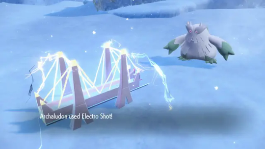
Terminals at the ends of its limbs gather and store static electricity, which Archaludon can use to fire a powerful beam made up of electric energy not normally generated within its body. Archaludon can gather static electricity more easily during storms and other inclement weather, allowing it to fire off its beam faster than usual.
When in trouble, Archaludon extends its normally bent torso, trading some of its mobility for a more stable center of gravity. While it’s like this, the Pokémon resembles a magnificent steel bridge.


With the new Electric-type special move Electro Shot, Archaludon gathers vast quantities of energy and fires off a high-voltage bolt of electricity. Under rainy weather conditions, Archaludon can immediately fire off this attack without having to spend time charging it up.


93 notes
·
View notes