#gqrx
Explore tagged Tumblr posts
Text
SDRアプリケーション
調べてみたところ代表的なアプリケーションがいくつかあったのでインストールしてみました。OSはUbuntu 22.04 LTSです。 その前にRTL-SDR.COM受信機がLinuxから認識できるようにドライバーをインストールします。このページに書かれた方法でやれば上手くできると思います。 ドライバーのインストールが終わったらRTL-SDR.COM受信機をUSBポートに挿して認識されることを確認します。 Realtek Semiconductor Corp. RTL2838 DVB-T の部分が受信機です。 以下、Linuxで使用できる代表的なSDRアプリケーションです。 CubicSDR Gqrx SDR++ 一通り電波を受信できることを確認したのみで詳細を比較するところまで今日はできませんでした。 このRTL-SDR.COMの受信機は使用していると結構な熱を持ちます。

View On WordPress
0 notes
Note
What is your area of study or work? What do I go into if I want to work with the squelch from that radio machine?
My background is a degree in electrical engineering with a tangential encounter with radio engineering, but just getting into amateur radio will have you squelching with the best of them in no time.
Easiest route into amateur radio is the RTL-SDR USB radio dongle and a laptop, you can use a program like GQRX to watch radio waterfalls and pick up random chatter across 1800MHz or so. Good for understanding what radio is doing and playing with it in a legally clear way, there's lots of YouTube videos and blog posts about toying with the RTL-SDR.
Once you have a handle on that, grab a cheap handheld radio like the Baofeng UV5R and contact your local radio club for information about your national ham radio examinations, while being aware that technically until you're licensed you're not allowed to hit the transmit button on your radio.
#I'm still not licensed because i missed the last exam cycle and now id have to take the exam in czech#so you know.#ask#anonymous#radio#ham radio
27 notes
·
View notes
Text
Digital Radio Spy
Digital Radio Spy: The Ultimate Guide to Staying Tuned In

What is Digital Radio Spying?
Using specialized hardware and software to record and decode signals from digital radio transmissions is known as “digital radio espionage.” Digital radio uses complicated encoding systems that call for more advanced equipment, in contrast to traditional radio, where the signal is frequently analog and reasonably simple to decode with a basic receiver.
This hobby or practice is widely used by:
Amateur radio enthusiasts: who enjoy exploring and listening to different frequencies.
Security researchers: testing wireless systems for vulnerabilities.
Aviation fans: listening to air traffic control (ATC) communications.
News agencies: to monitor emergency services and breaking events.
The Evolution of Radio Technology
Before we dive into the tools of digital radio spying, let’s take a brief look at how radio technology has evolved:
AM/FM Radio: Amplitude modulation (AM) and frequency modulation (FM) were the main ways to transmit audio signals over the airways for many years. These technologies have long been a part of radios found in homes, cars, and portable electronics.
Digital Radio: Digital radio emerged as a result of technological advancements, providing improved sound quality, increased content availability, and data transmission capabilities (such as text, photos, and more).
SDR (Software-Defined Radio): This is the application of digital radio espionage. SDR offers greater flexibility and usefulness by using software to tune into frequencies and decode digital signals rather than relying on conventional hardware receivers.
How Does Digital Radio Spy Work?
SDR technology is the foundation of digital radio espionage. You attach a software platform to hardware intended for capturing radio signals in place of a physical radio receiver. After then, the software can be configured to detect a large spectrum of frequencies, interpret the signal, and display it in a format that is useful.
Here’s a basic breakdown of the setup:
SDR Hardware: You may record radio waves with this gadget, which you can link to your phone, tablet, or computer. RTL-SDR dongles, HackRF, or more sophisticated SDR receivers for experts are common choices.
SDR Software: You’ll need software to decode and interpret the signals. Some of the most popular programs for digital radio spying include:
SDR (SDRSharp): A highly popular software for Windows that supports RTL-SDR and other SDR hardware.
Gqrx: A widely-used SDR application for Linux and macOS.
CubicSDR: Cross-platform SDR software with a simple and intuitive interface.
Antennas: A single SDR device is insufficient. To pick up the precise frequencies you want, you’ll need the right kind of antenna. Different antennas can be needed depending on if you’re interested in UHF, VHF, or other bands.
Decoders: Decoders are required in order to decode digital signals, which can include encrypted data, digital voice, or digital television signals. Tools like DSD+ can aid in decoding digital voice, but other applications may be necessary for more specialized forms.
Popular Uses of Digital Radio Spying
Digital radio spying serves multiple purposes, depending on the type of signal being captured. Here are some of the most common uses:
1. Monitoring Air Traffic Control (ATC)
Digital radio eavesdropping is a tool used by aviation enthusiasts to listen in on pilot-to-air traffic controller interactions. Even while this is quite lawful in many regions of the world, it’s crucial to confirm your local laws.
2. Tracking Maritime Communications
SDR can be used to intercept and decode signals from ships and marine communications, including emergency broadcasts, in a manner similar to ATC monitoring.
3. Decoding Weather Satellites
One exciting application is decoding messages from weather satellites. You can directly obtain photos and meteorological information from satellites orbiting the Earth by intercepting these transmissions.
4. Amateur Radio Listening
A lot of digital radio spies also listen in on amateur radio broadcasters on different frequencies. Listening to global HAM radio enthusiasts is possible with SDR.
5. Emergency Services Monitoring
Emergency services continue to use analog or digital transmissions in some areas. In the event that these messages are not encrypted, digital radio spies could be able to hear them. However, it is prohibited in many jurisdictions to listen to encrypted emergency services.
Ethical Considerations
While there are many interesting potential for digital radio espionage, it’s crucial to keep in mind that there are important ethical and legal considerations. Understanding the laws governing radio interception in your nation is crucial. It may occasionally be unlawful to listen to specific frequencies, such as those utilized by the military, police enforcement, or encrypted services.
Ethical digital radio spying means respecting these boundaries:
Do not intercept encrypted signals unless authorized.
Avoid using the information gathered for illegal purposes.
Respect privacy laws and regulations, especially when dealing with personal or sensitive data.
The Legal Landscape of Digital Radio Spying
The legalities surrounding digital radio spying vary by country. Here are some general guidelines:
In the United States, Radio transmissions are governed by the FCC, and it is illegal to intercept some messages without authorization, particularly those that are encrypted. It is, however, usually acceptable to tune in to open, unencrypted broadcasts such as amateur radio or ATC.
In the United Kingdom, Ofcom oversees radio communications, and it is illegal to listen to any broadcast that you are not authorized to hear, including emergency services, private business communications, and encrypted transmissions.
In Australia, the Australian Communications and Media Authority (ACMA) regulates radio communications, and similar rules apply. However, amateur radio and weather satellites are typically open to interception.
Before starting any digital radio spying activities, always research the specific legalities in your country to ensure you’re complying with the law.
Getting Started with Digital Radio Spy
If you’re eager to dive into the world of digital radio spying, here’s a basic list of things you’ll need to get started:
An SDR Receiver: The most accessible and budget-friendly option is an RTL-SDR dongle. For more advanced users, devices like the HackRF or Airspy offer higher performance.
Software: Download SDR# or CubicSDR to get started. These programs allow you to tune into frequencies and decode signals.
Antennas: Depending on your focus, you may need different types of antennas for UHF, VHF, or HF bands.
Decoding Software: If you’re capturing digital signals, you’ll likely need additional software like DSD+ to decode digital voice or satellite data.
Patience and Experimentation: Digital radio spying involves a bit of trial and error. Start by exploring publicly available frequencies, and gradually work your way toward more complex signals.
Future Trends in Digital Radio Spy
The future of digital radio spying looks promising as technology continues to advance. We can expect:
Improved SDR hardware: With higher sensitivity and greater frequency range, future devices will allow for even more in-depth signal analysis.
More decoding tools: As digital radio formats evolve, so will the tools designed to decode them, making it easier for enthusiasts to capture and interpret signals.
Integration with AI: Artificial intelligence could play a role in analyzing and interpreting large volumes of intercepted data, automating some of the more complex aspects of digital radio spying.
Conclusion
Digital radio spying is both an engaging pastime and an effective tool for experts, researchers, and enthusiasts. You may access a world of secret signals using SDR technology, including air traffic control communications and weather satellite signals. But it’s crucial that you approach this activity knowing what the ethical and legal requirements are in your area.
Article Source :- https://medium.com/@EuspyshopUK/digital-radio-spy-0e904d55ff92
0 notes
Text
playing with gqrx today :) and reading last chapter of Higurashi. My head hurts a little but I'm enjoying myself
1 note
·
View note
Text
Skywave Linux v4.1 Released
youtube
#Skywave Linux#Software Defined Radio#OSINT#Shortwave Radio#Mediumwave Radio#code editor#Gqrx#CubicSDR#Neovim#Jupyter Notebook#Youtube
1 note
·
View note
Text
Skywavelinux 4.0 is released. Enjoy the fresh and responsive realtime Xanmod kernel 5.6, Ubuntu MATE 20.04 base, and the i3 window manager.
It has hardware drivers and SDR apps out of the wazoo. SoapySDR, Gr-OsmoSDR supporting Gqrx and CubicSDR.
1 note
·
View note
Text
DragonOS - Como Criar um Pendrive/HD Ubuntu USB Persistente
DragonOS - Como Criar um Pendrive/HD Ubuntu USB Persistente Veja como instalar o DragonOS e vários Linux em um pendriver/HD USB com persistência. O DragonOS é um OSl pronto para ser usado por qualquer pessoa interessada em RTL-SDR.

O tema principal deste post seria o projeto “DragonOS”, que é um ISO Linux pronta para instalar, destinada a facilitar a vida dos iniciantes nos softwares SDR. O DragonOS fornece vários programas pré-instalados e, recentemente, a compilação foi atualizada, desta vez com base no Lubuntu 18.04, permitindo suporte para Legacy e UEFI, além de criptografia de disco. O sistema operacional suporta RTL-S…
View On WordPress
#Aircrack-ng#bladeRF#cubicsdr#DragonOS#GNU Radio#gqrx#gr-gsm#HackRF#IMSI-catcher#inspectrum#Kalibrate-hackrf#Kismet#Limesuite#lsblk#LTE-Cell-Scanner#mkusb#OP25#qspectrumanalyzer#RTL-SDR#rtl_433#SDRAngel#SDRTrunk#ShinySDR#SoapySDR#ubuntu#UEFI#Universal Radio Hacker#USB Persistente#Wireshark#Zenmap
0 notes
Text
LimeSDRをGQRXで使ってみる
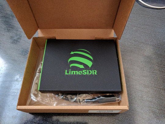
キャンペーンは昨年の4月でした。デリバリは11月予定だったはずなのでちょっと遅れたというところです。
2016/4/29 キャンペーン開始
2016/4/29 さっそくBackする
2016/6/22 ファンディング成功
2016/7/29 コネクタをMicro-Bに変更
2017/1/27 出荷
2017/2/5 受領
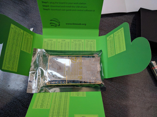
箱は黒いスリーブにレーザカッターでロゴが抜かれて内箱の緑が見えています。添付はUSB micro-Bのケーブルのみです。電源補助用のAプラグが二股になっています。

内側には携帯やWiFiなどのバンド番号と周波数(DL/UL)の表が書かれています。地味に有り難いです。
基板は小さく密度は高いです。購入時にUSBコネクタを選べますが、USB micro-Bにしました。他にUSB Aプラグタイプが選択肢にあります。
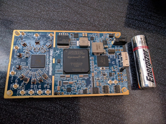

裏面にも部品が詰まっています。プラの6角スタッドが足として付いています。おぉっと思ったのは、おなじみのSi5351が使われています(AではなくC)。
bladeRFとくらべるとかなり小さいです。bladeRFは部品の配置に余裕があり、さらに拡張コネクタも装備されていました(結局使いませんでしたが)。それに対してLimeSDRは部品の密度も高く、拡張コネクタもFPGAから出ている10ピンのGPIOのみです(JTAGと同じコネクタ形状)。
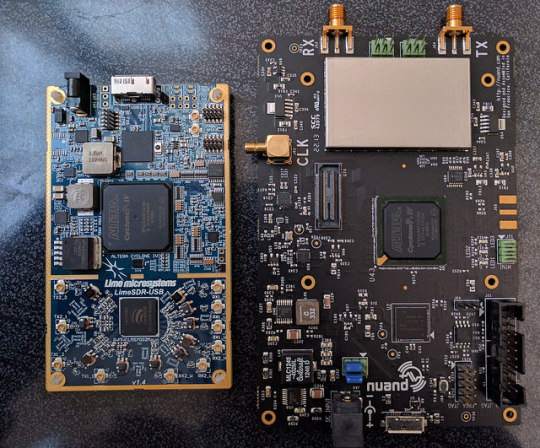
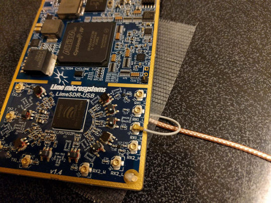
肝心のRFコネクタですが、なんとU.FL(IPX)でごく小さいのです。TX,RXともに2チャネルずつ用意され、さらにTXはチャネル毎に2つ、RXもチャネル毎に3つコネクタが装備されているので、合計2x2+3x2=10個もあります。このようにポート数がとても多いため、SMAではスペースが確保できずU.FLを選択したのだ��思われますが、ちょっとやり過ぎの感も否めません。U.FLは機械的強度がとても弱いので、何度も付け外しを繰り返すことができません。早急にケースに入れてケーブルを固定してしまうことが必須だと思われます。今回は仮にUFLのついたケーブルを机にテープで仮止めして外れないようにしています。
ソフトウェアは、例によってmacosにセットアップします。これを機会にようやくsierra(10.12)にバージョンアップしました。
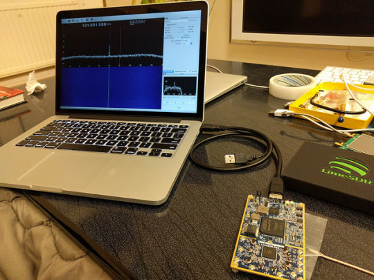
LimeSDR用にLimeSuiteとしてツールがいくつか用意されています。これも公式ページに従ってbrewでインストールしておきます。
$ brew tap pothosware/homebrew-pothos $ brew update $ brew install limesuite
コマンドラインツールのLimeUtilでボードが認識できたら、さっそくファームウェアをアップデートしておきます。
$ LimeUtil -info $ LimeUtil -update
LimeSuiteGUIというグラフィカルツールも用意されています。ボードに載っている各デバイスを細かくコントロールできるようです。動作させるためには、メニューのOptionsからConnection Setupでまずは接続を行う必要があるようです。ちょっとまごつきます。
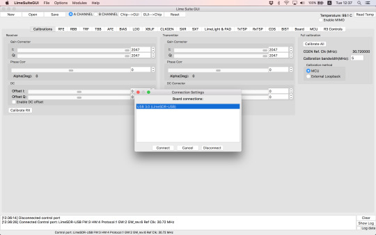
SDRソフトウェアとしてgqrxをlimesdrで動作させることができるようです。そのためにはソースからビルドする必要があるため、各種ツールキットをインストールします。下記はbrewであっさりとインストール可能です。soapysdrは、SDR関連のライブラリやツールをまとめたSuiteとのことです。
gnuradio
soapysdr
下記はコードからビルド必要でしたが、今回brewのFormulaを用意/アップデートしました。githubに上げてありますので、brew tap ttrftech/gqrxで利用可能です。
gr-iqbal
gr-osmosdr
gqrx
インストールに成功したら、gqrxを起動します。LimeSDRはsoapyというインターフェースで使用する必要があるので、デバイス設定として、
driver=lime,soapy=0
を指定します。起動がうまくいかないことがたまにありますが、もう一度実行するとOKだったりします。Input rateは8000000(8Msps)から55000000(55Msps)程度が指定可能でした。仕様上は上限60Mspsだったはずですが、これを指定すると起動できませんでした。

50Mspsの指定で動作さ��てみ���す。RTLドングルに付属していたアンテナをU.FLコネクタに接続します。最初は何も受信できずに焦りました。

設定が2箇所必要でした。まずアンテナポートを選択する必要があります。デフォルトではNONEになっているので何も受かりません。アンテナを接続したポートをプルダウンメニューで選択します。LNAH,LNAL,LNAWがRX1-H,L,Wにそれぞれ対応しているようです。RX2には未対応のようです。
そしてもう一つは、ゲイン設定を上げる必要があります。必須なのはLNAでこれは最大にします。他の設定ではレベルは変化しますが、NFは変化しないようです。適宜設定します。


そうすると受信できるようになりました。この画面では地上デジタルTVの3波がわずかの隙間を空けて並んでいるのが見えています。
ちょっと周波数を上げるとこちらも地デジが1チャネル分の隙間を空けて並んでいます。サンプリングレートが高いので、50MHzの帯域を一度に見ることができます。
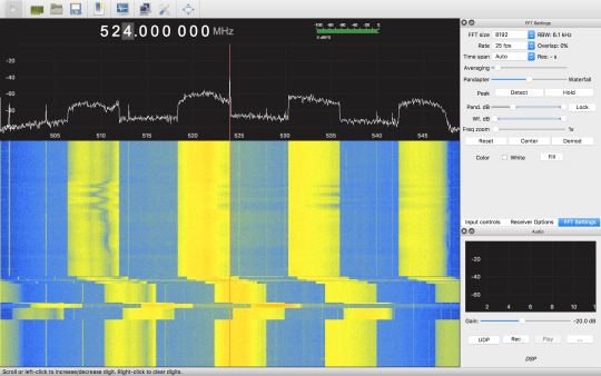
もっと周波数を上げると携帯の周波数が見えてきます。 4つの帯の左からKDDIのLTE, 3G, Docomoの3G,LTEのDL(Down Link)です。
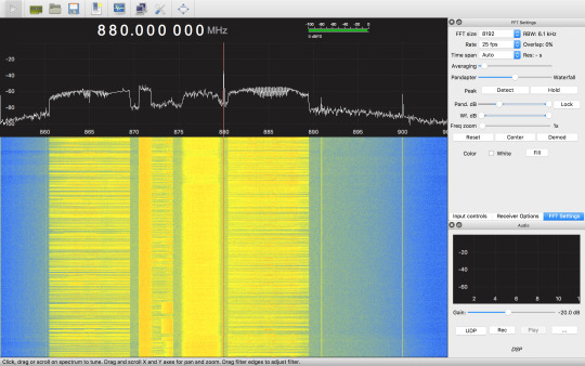
1.5G帯にも携帯の太い帯が見えています。

2.4Gでは室内の通信が見えています。一瞬出る横幅の太い線はWiFi(11gの20MHz幅)。点々と散らばっているのはおそらくBluetoothの周波数ホッピング(FH)です。

とりあえず、受信機として正常に使えているようです。
LimeSDRは0.1〜3800MHzというとても広い帯域に対応していることが謳われていました。気になる低い周波数ですが、300MHz以下を受信可能なことは一応確認しました。しかし顕著に感度は下がって行くようです。特にHF帯ではちょっと実用性は無さそうな感じです。��料を読むと30MHz以下の低い周波数の対応は、チューナではなく信号処理段で特別な処理を行うようですので、もしかすると使い方が足りていないか、まだ対応がされていない可能性もあります。
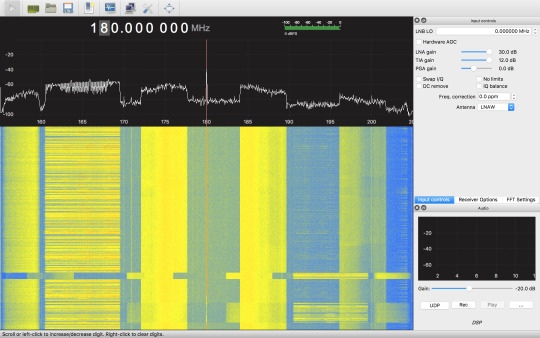
もう一つ気になることは、300MHz以下ではイメージが顕著に出ることです。例えば180MHzにチューニングすると明らかに地デジの帯が出てきます。右には違う周波数帯の携帯も見えています。チューニングをずらすとばらばらにズレていきます。このチップ(LMS7002)のチューニングスキームを理解できていませんが、300MHz以下の受信をしたい場合には、広帯域信号では不都合があります。適当なLPFで帯域を絞った信号を入れる必要があるようです。
使っているとチューナチップとFPGAどちらも結構発熱します。USBからは7〜800mA消費しているようです。
gqrxでの受信を試してみた印象ですが、300MHz以上の周波数帯では感度も良く、快適に使えそうです。元来WiFiやBluletoothの実験に供することを主眼に設計されているようですので、当然かもしれません。一方、低い周波数での応用は、特に無線用途では難しいと思われます。謳われているスペックを鵜呑みにするとがっかりすることになると思います。
さて、LimeSDRは受信だけでなく、信号生成機能もあります。bladerfではコマンドを使ってデータストリームを送受できたのですが、limesdrでは見当たりません。おそらくgnuradioを使うことで利用できるのではと思うのですが、こちらはまた探ってみたいと思います。
リファレンス
クラウドファンディングサイト CrowdSupplyでのLimeSDRキャンペーン https://www.crowdsupply.com/lime-micro/limesdr
LimeSDR公式 https://wiki.myriadrf.org/LimeSDR
ユーザガイド https://wiki.myriadrf.org/LimeSDR-USB_User_Guide
クイックスタートガイド https://wiki.myriadrf.org/LimeSDR_Quick_Start
LMS7002 Datasheet (wiki) https://wiki.myriadrf.org/LimeMicro:LMS7002M_Datasheet
公式のLimeSuiteインストール手順 https://wiki.myriadrf.org/Lime_Suite#OSX_homebrew
Gqrx http://gqrx.dk/
参考にした先人のgqrx構築手順 https://discourse.myriadrf.org/t/anyone-been-successful-in-getting-limesdr-osx-gqrx-working/657/14
今回作成してみたHomebrewのFormula https://github.com/ttrftech/homebrew-gqrx
3 notes
·
View notes
Text
SDR Research
Tools
GQRX - Spectrum Analyzer
RFanalyzer - Spectrum Analyzer for Android
Universal Radio Hacker - Investigate Wireless Protocols like a boss
ooktools - On-off keying is used extensively in IoT projects
fldigi - I'm not a big fan of fldigi, but its there for when you need to demodulate a common signal
Tools for more specialty purposes
Salamandra is a tool to find spy microphones
rpitx is a RF transmitter for Raspberry PI
Tactics
You don't need to learn DSP, or get your Ham license to explore radio signals. I didn't. You could even explore interesting signals such as vehicle key fobs without learning either, but learning these things will increase your understanding of signals and aid in your ability to go beyond the limitations of your tools.
Digital Signal Processing
The Scientist and Engineer's Guide to DSP was my introduction to DSP and I highly recommend it. Its free online and can be purchased in physical form.
Think DSP in Python is on my todo list. Also free online can can be purchased in physical form.
HAM Radio
Though I haven't taken the test yet. Covid was a major interruption in my plans, and I also plan to pass all 3 tests in one day. Using my personal test taking process, I would first start by reading No-Nonsense Study Guides.
Then take a pretest. Its important that you read all of the material before you take a pre-test as the goal is to retain knowledge, not just memorize a test. Most of the study should be reading/practicing the material, with few pre-tests as self assessments.
There are plenty of apps on Android (and I imagine IOS) that you can use. You need to get 74% to pass the exam, but I always shoot for 90%. If you get 90% on the pre-test, then move on to taking the actual exam.
If you didn't get 90% on the pre-test. The pre-test should be able to break down your score across various sections. Note the sections you're weakest in. From here, I would recommend switching over to the ARRL study guide as they are more detailed and only study the sections you're weakest end. When you complete all those sections, then take another pre-test and repeat until you're ready to take the exam.
Techniques
Accuracy
Radio is a science, but the tools that we can afford as hobbyists are not accurate. The three issues I face is drift, noise, and clock.
Drift occurs typically from your SDR getting hot and is a problem that grows across the session. To counter drift, you'll need to recalibrate your SDR to a Nation Weather Radio station. Find the frequency used in your area and tune to that frequency. You'll notice that you're probably a little off, this is the fault of your SDR not the National Weather Radio station. Set the offset of your SDR until your frequency of the station matches the one advertised. You'll then want to bookmark this frequency and check back to it every hour to insure that your SDR hasn't drifted.
Noise can interfere with interpreting weak signals (either distant, low powered, or both). To reduce noise and improve your signal collection, I'd suggest these guides for reducing on-site noise sources and external noise sources.
Signal Identification
Most signals are standardized or frequently used that dont require extensive analysis, but just identification.
The Signal Identification Wiki is a great place to start, and if that doesn't work, check out the sub-reddit r/signalidentification
This is an archived site that has a collection of digital signals that you could test your demodulation tools with.
Signal Analysis
Signal analysis is for those proprietary signals. As always, remember your ABC's.

Radio signals are fleeting. If you don't capture them, they may not repeat themselves. Don't worry about demodulating them at first. Capture the signals, and you can demodulate them at any time later.
Even if you're not able to record IQ data, for example you're listening to someone else's remote radio (there are a lot around the world on the internet), recording the audio which can be analyzed by tools such as fldigi.
I should add a lot more stuff here in the future.
The Signal Identification Wiki is a great place to start, and if that doesn't work, check out the sub-reddit r/signalidentification
This is an archived site that has a collection of digital signals that you could test your demodulation tools with.
Other Techniques
Using ooktools
NCC's RF testing Methodology
Wireless DoorBell Ringer and another Doorbell hack
Learn Morse Code
Project Ideas
Passive Radar with SDR
TDOA Transmitter Localization with RTL-SDRs
Other Links
No SDR, no problem! Use other people's radios with GlobalTuners.
#radio#signals#radio transmissions#sdr#ham radio#DSP#digital signal processing#signal analysis#technology
2 notes
·
View notes
Text
GQRX en MacOS
Configurar GQRX
Poner en funcionamiento GQRX
View On WordPress
0 notes
Text
“Hello World” in morse: turning an FPGA into a radio transmitter
I’ll try here to explain everything that is going on in this picture, but first, the origin story. I recently tweeted this photograph of my first ever FPGA project:

Actually this is from a slightly different angle. Bonus! I got more attention on twitter from this than I’d ever gotten before, with lots of notifications on my phone throughout the next days, and of course I’m super flattered. So when a few people request a better explanation I can’t say no!
Even though the people who responded to this are probably a highly technical audience, I’ll try to start very basic and include a lot of links, for the benefit(?) of my other acquaintances whom I’ll pester to read this - so feel free to skim ahead if you’d like.
What is an FPGA?
First, what is this FPGA thing? You can see one in my photo, in front of my keyboard, connected to my computer by a white USB cable. Although this one is small, it contains a lot of the basic components from which digital circuits (like a CPU) are built: logic gates which can compute things, and flip-flops and RAM which can store stuff.
But unlike a CPU, the components in an FPGA are reconfigurable: you get to decide how they are connected together. And you can do it without having to solder millions of tiny wires and losing tiny transistors between the keys in your keyboard. Just describe how you’d like the circuit to be connected on your PC, using a “drag-and-drop and draw wires” program or a text-based “hardware description language”, and through the magic of logic synthesis you can make your circuit come alive within the FPGA.
The trick to it is that all the components in the FPGA are already all connected together in lots of ways, and your computer is just telling the FPGA which of these connections should be on or off - like a light switch decides if your lamp should be connected to power or not.
There are also connections from inside the FPGA to the outside of the board, where you can connect external components like an LED, an LCD display or a keyboard to your circuit.
The specific FPGA I’m using is the TinyFPGA BX. It’s small, very cheap at $38, and is fully open source hardware. All the software you need is open source too, so it’s all free and easy to get access to, and the TinyFPGA page has lots of great links to everything you need to get started.
How did I turn it into a radio transmitter?
Here comes the plot twist: it was a radio transmitter all along.
In order to keep the digital logic of the FPGA in sync and working in unison, it is equipped with an oscillator which transmits a clock signal - a signal that switches between high and low at regular intervals. You’ve probably heard about “clock rates” before, because it is one of the things that decides the performance of a computer, and these days it is usually measured in GHz.
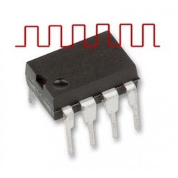
Now simply by directing the FPGA to route the signal from this clock source out to one of it’s external connections, and connecting it to a small piece of wire, we have a radio transmitter! See the screenshot of this setup in the Icestudio FPGA programming environment, possibly the simplest example imaginable:

The output, and the wire connected to it, will be driven to high and low voltage levels by the clock signal, and waves of electromagnetism will spread out across the universe. Imagine the piece of wire (or “antenna”) as a tiny oar splashing up and down in the fabric of space time, in rythm with the clock signal.

But there are some serious disadvantages to the radio signal we are generating here. First, the “oar” of the antenna is very small, and the “muscle” of the clock signal is not very strong, so it’s can’t make very big waves - the transmission is not very powerful. But that is probably for the best, because trying to transmit using a square wave like the 16MHz clock signal will, in addition to a signal on 16MHz, create a lot of “harmonics” - unwanted signals on other frequencies.
Because I’m an amateur radio enthusiast, I have a very nice radio receiver sitting on my desk that can receive and display the transmitted signal in a very nice way (specifically a LimeSDR, It’s visible on the right in my first picture). Here’s a screenshot from GQRX, the program I’m using to control it:

It’s tuned to 16 MHz (the red vertical line), but you can also see some more of the radio spectrum on each side of it. In addition to the sharp peak of the main signal on 16MHz, there is a very apparent cloud of noise surrounding it - which we can see here as a raised area on the "panadapter” up top, or a brighter, yellow color around the 16MHz line on the “waterfall” below. There are also weaker, but still very visible symmetrical peaks to the left and right of the main signal.
Outside of what we can see in this screenshot, there’s also strong “harmonics” being transmitted on other frequencies, like 8 or 24 MHz. In short, what we’re doing here is generating what’s usually called EMI - ElectroMagnetic Interference, and it’s a Bad Thing™. This is the reason real products need conductive shielding, and try to keep wires as short as possible to keep them from acting as antennas. And of course, you should never connect a signal like this to an amplifier - because you don’t want to end up disturbing someone’s pacemaker or interrupting emergency communications.
(Just to make sure noone gets the wrong idea, the TinyFPGA BX itself seems well shielded and I’m hardly able to detect it being on without attaching the “antenna”.)
What you’d want, and what “real” radio transmitters generate, is something closer to a nice smooth sine wave like this:

Now it’s quite possible to get from a square wave to this, by passing the signal through a “filter” which can be easily constructed from inductors and capacitators. Well, if you consider soldering tiny components easy ...
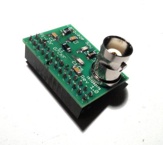
I was able to assemble a kit for such a filter, allowing me to transmit “real” radio signals from the output pins of a Raspberry Pi with no additional components, and be received across town several kilometers away! And although that was with a much better antenna, it was without any amplification. So again, a warning about being very careful about what you transmit, intentionally or unintentionally, because even very weak signals can be heard quite far away.
Now there’s a couple of more things that are Bad™ about the 16MHz square wave signal we generated earlier: First, it’s not a frequency on which I am legally allowed to transmit(!). The radio spectrum is quite heavily regulated, but there are some frequency ranges for “free” use. These are typically quite crowded. There is one area around 433 MHz that is used heavily by all sorts of gadgets like wireless temperature monitors or doorbells, and another around 2.4GHz which is very heavily used by Wi-Fi, Bluetooth and other high-bandwidth devices.
The other problem with our original signal is that it is very boring - just a steady buzz at 16MHz, hardly worth transmitting or listening to.
As a licensed (though inexperienced) amateur radio operator (my callsign in LB7HH!), I also have permission to transmit on amateur radio bands, with certain requirements. One of them is that during any transmission, I have to regularly include my call sign.
So with some copy-pasting and slight tweaks, here’s my first FPGA project:
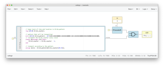
The large rectangle on the left is a block of Verilog hardware description code - it’s a slight modification of the code from the TinyFPGA-BX project template. The code in the template blinks the LED in a SOS morse pattern. By doubling the size of the string, I was just exactly able to fit my callsign in morse code instead!
To the right, I first use the builtin “PrescalerN” component which can reduce the clock frequency by dividing it with 2^N. Lucky for me, there is a value of N that results in a frequency I’m legally allowed to transmit on - 2MHz, which is exactly the upper edge of the 160M band.
The last component is an AND gate which combines the two signals, only letting the 2MHz frequency signal through when the morse signal is high. And then it’s connected out to PIN_2 and my “antenna”. And that’s all there is to it.
So how powerful is this transmitter? I haven’t done the math, but judging by what similar hacks can do it should be around milliWatt at most, and with a very poor antenna the effective radiated power is much lower still. Which is actually a good thing, as I didn’t build that filter for 2MHz yet.
And I probably won’t, because the project I got this FPGA for is actually very different - implementing my own CPU design. I’ll just have to learn a lot more Verilog first ...

2 notes
·
View notes
Text
ISS Slow Scan TV (SSTV)
No 8. lidz 10. februārim norisinājās ARISS / NOTA ISS SSTV pasākums. Arī man, par prieku pirmo reizi, veiksmīgi izdevās uztvert no ISS sūtītu signālu. Ideja sekojoša - Satelīts lidojot savā orbītā, sūta radio signālu 145.800 mhz frekvencē. Šis signāls ir modulēts (PD120) modulācijā, to var dekodēt.
Apbruņojies ar 3 elementu 2m yagi antenu, RTL SDR puļki un datoru, veiksmīgi, sekojot doplera frekvencei ar Gpredict, kopā ar Gqrx un tad jau uztverto signālu padodot uz dekodēšanas programmu Qsstv, izdodas saņemt šo bildi:

Temperatūra laukā gan bija 2-4 grādu robežās, kā rezultātā kopumā pavadot ap četrām stundām vieglā vējā un mitrumā diezgan nosalu.

Un saldajam ēdienam...
Iesniedzot uztverto bildi, pasākuma rīkotājiem, pēc aptuveni nedēļas, saņēmu diplomu, kā apliecinājumu par piedalīšanos.
Jau ielaminēts, ierāmēts un pielikts pie sienas ;)

73 de YL3CAAK!
1 note
·
View note
Photo
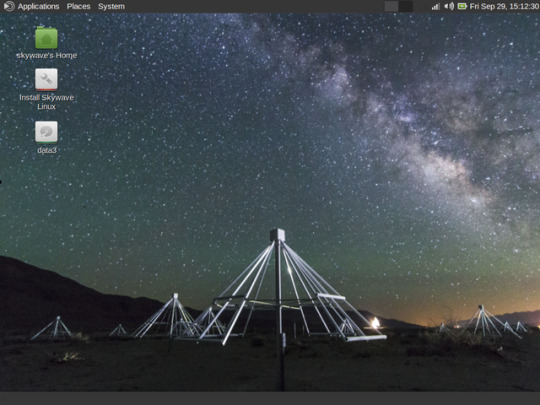
Skywave Linux 3.0 is released. This version has a different look, now using the MATE desktop environment. It is efficient and has visual appeal. We're now on the Xanmod Kernel 4.13, which makes for a responsive and stable base system. Audio now starts as a plain PulseAudio system, without plugins, for greater hardware compatibility. More wifi drivers are also included in Skywave Linux 3.0. Multiple desktops are enabled, so users can de-clutter and organize their activities on the system. As to the software defined radio applications, we now have four sources of remote servers: WebSDR, OpenWebRX (KiwiSDR), QtRadio/HPSDR, and RemoteSDRClient (SDRAnywhere). The latter is the newest and connects to shared RFSPACE radios. RTLSDR applications are now moving into new capabilities: simultaneous multichannel monitoring, data logging, and ability to stream audio to shoutcast servers. ACARS and VDL Mode 2 are now decodable, with logging. Bleeding-edge support for ADALM-PLUTO devices has been added. Kodi has received some updates and continues to offer streams from thousands and thousands of sources. Those stations sound great with the dynamics and EQ processing in PulseEffects. Overall, this version of Skywave Linux does more, makes better use of system resources, and is a joy to use.
#Software Defined Radio#Gqrx#CubicSDR#RTL-SDR#ACARS#VDL mode 2#ADS-B#Kodi#Linux#Amateur Radio#Shortwave Listening
4 notes
·
View notes
Text
PothosSDR - Melhores Ferramentas RTL-SDR Para Windows
PothosSDR – Melhores Ferramentas RTL-SDR Para Windows
O Pothos SDR é um ambiente de desenvolvimento que inclui o conjunto de softwares de fluxo de dados Pothos e ferramentas gráficas, SoapySDR e kit de ferramentas pothos-sdr para hardware que fazem interface com vários drivers de fornecedores de hardware SDR comumente usados e kit de ferramentas GNU Radio para suporte ao processamento de sinais
O instalador do PothosSDR está disponível aqui.
A…
View On WordPress
#cubicsdr#demodulação de WBFM#GNU Radio#gqrx#libusb#PothosFlow#PothosSDR#RTL-SDR#rtl_adsb#rtl_fm#rtl_power#rtl_sdr#rx_fm#rx_power#rx_sdr#SoapySDR#SoapySDRUtil#Spectrogram#Windows#Zadig
0 notes
Text
Raspberry Pi Disk Images
Raspberry Pi Disk Images
Raspberry Pi Disk Images……… Audio and Music Disk Images Please also note, our list of available Raspberry Pi Audio HATs (Hardware Attached on Top), which greatly increase the sound quality of your Raspberry Pi here). Gqrx Gqrx is an open source software defined radio receiver (SDR) powered by the Gnu Radio and Qt graphical toolkit. You can download the Raspberry Pi disk image for…

View On WordPress
0 notes
