#electric board edge connector
Explore tagged Tumblr posts
Visit Tumblr Blog
Explore Tumblr blogs with no restrictions, modern design and the best experience.
Last Seen Tumblr Blogs


Fun Fact
The total number of visits Tumblr.com received during January 2021 is 327 million.
Text
https://www.futureelectronics.com/p/interconnect--backplane-connectors--backpanel-connectors/188835-1-te-connectivity-5170771
Backplane connector types, Wire connector Receptacles, Power Jacks
Z-PACK Series 154 Position 2 mm Pitch Press Fit Through Hole Backpanel Connector
#TE Connectivity#188835-1#Backplane Connectors#Rack and Panel Connector#Wire connector Receptacles#Power Jacks#card edge connector#high-speed#electronic connector#electric board edge connector#socket mount wire
1 note
·
View note
Text
https://www.futureelectronics.com/p/interconnect--pin-and-socket-connectors--crimp-terminals/2-520102-2-te-connectivity-1904077
Crimp Terminals, Socket mount wire, Circular connector, 6 Pin Contacts
Ultra Fast 22-18 AWG Straight Fully Insulated Receptacle Assembly
#TE Connectivity#2-520102-2#Connectors#Pin and Socket Connectors#Pin Contacts#Pin Through Hole Coin Cell Holder#receptacle socket#Electrical circuit#Board mount connector#edge connector#Crimp Terminals#Socket mount wire
0 notes
Text
How to Make: Electronic Wings for Cosplay

Hello Everyone! It's been a while since I last uploaded a written tutorial on here and since I just finished and wore my Dame Aylin cosplay this last weekend it seemed appropriate to jump back in with a tutorial on one of the costume pieces!
Her wings were the star of the show this weekend and I know a lot of people were curious about how I made them! A huge source of knowledge and inspiration behind these wings was this video by Axceleration, I made a few changes to the frame shape and electrical circuitry for mine but her tutorial was a huge stepping stone to give me the confidence to tackle them myself!

Health and Safety:
When working with Sintraboard (as well as other thermoplastics) it is incredibly important you wear a respirator as well as goggles when heating, moulding and cutting it. The fumes this plastic will give off when heated up are no joke! Make sure you're in a well-ventilated space!
Basic tool safety knowledge is also really important! wearing gloves when using power tools can be more dangerous in most situations, so always be aware of where your hands are vs where the tools are. Always cut away from yourself and take things slowly, don't panic.
Electrical safety! You're working with live wires and circuitry! make sure your hands are dry, you aren't touching the bare wires at any point when they are connected to a power source, and if you choose to solder anything, make sure you're wearing heat-proof gloves and a mask in a ventilated space!
Tools
Wire stripper
Screwdriver and wrench
Dremel - I recommend the Dremel 3000 rotary tool personally! Some essential Dremel bits you'll need for this include, a sanding bit, drill bit (smaller or same size as your screws/bolts), and a small/narrow cutting bit. These will usually come with the Dremel!
Heat Gun (A hairdryer will not get hot enough to heat the Sintraboard!!)
Pipe cutter (alternatively you can use a hacksaw for this!)
Hacksaw
Ruler
Scissors (for cutting fabric straps)
Materials
Heat shrink Tubing
2 core electrical wire
switch (you want a three position, six pin switch, like this one, even better if it has the Screws on the pins! otherwise you'll need a soldering kits to solder the wires to the pins.
2x 8AA 12v Battery Holders
2x 12v Linear Actuators (Mine had a stroke length of 100mm)
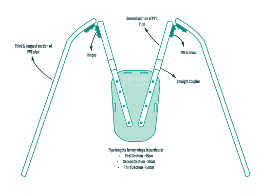
21.5mm PVC Pipes (I got 2x 3m Lengths)
2x 21.5mm PVC Pipe straight couplers
6mm 8"x12" Sintraboard
Nuts/Bolts/Screws (I used M5 bolts for the base & Actuator connectors and M6 screws to attach the hinges to the pipes! You'll need Washers for every Nut & Bolt!)
Hinges (I used 2.5cm wide hinges that were skinny but long so they would just about fit along the PVC pipe! 3" gate hinges would work!)
50 metre Polythene Jiffy foam roll (in retrospect this was ALOT of foam, you could definitely get away with maybe a 20-30 metre roll! I now have a load leftover XD)
16 AA Batteries (I used 16 and had enough for the whole day with them on, I think They'd probably be enough for another half a day-full day too! but have spares just in case!)
Webbing strap ( I went for grey to match my base suit colour!)
Buckle - as wide as the webbing strap you use!
3 metres of white cotton fabric (or whatever colour wings youre going for!)
Optional
Zipties (for cleaning up the wires)
Lets Go!
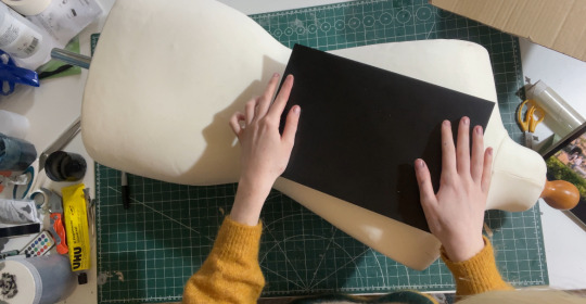
Sintraboard is this wonderfully stable thermoplastic that is relatively easy to cut into (with the right tools) and when heated allows you to mould its shape! I started by using a mannequin and heating the Sintraboard with a heat gun for a few minutes to make it pliable, I recommend using gloves for this part as the materials gets VERY HOT! Press the board into the shape of the mannequin's back, taking note of the edges especially! you want this board to sit as comfortably to your body shape as possible as it makes a huge difference to how long you can wearing the wings for in this backplate is comfy!
Once shaped, I placed it against my back to make sure it was a good fit, heating again and making any alterations I needed (again don't place bright hot plastic to your bare skin! wear protective clothes and wait till its slightly cooler to do this, with the help of a friend!). I then took a hacksaw and rounded the corners, before sanding the edges with my Dremel! Try to avoid cutting off loads, just enough to make things less likely to snag.
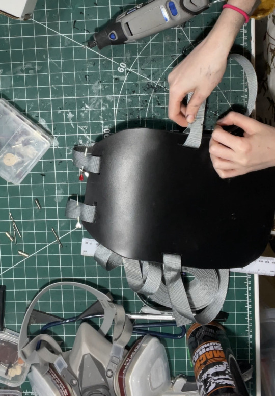
3. I then cut in four holes, wide enough to feed my webbing strap through, two at the top and one on either side below where my arms would sit! I measured the webbing strap by firstly feeding them through the top holes and pinning them, and then bring the strap over my should to everything sits where it should and seeing where the strap hits the side hole and cutting the length there! you'll also want a strap that attaches across the chest, meeting in the centre with a buckle!
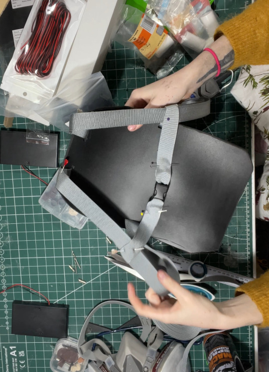
4. After sewing the straps closed I was able to move onto the PVC pipe structure! This may change slightly depending on the finished shape you want but I needed the PVC pipes to come out from inside a breastplate so had a particularly angle as well as character references to work with! I began by heating the pipe over my heat gun and flattening a portion of it under a heavy object so it would sit much more flush against the backboard and sit better underneath my breastplate before moving onto securing the first portion of the structure to the backplate. This mainly involved lots of try-ons and measuring to make sure the angles were correct and symmetrical and was quite fiddly but well-worth the effort! I'll include a diagram of the general shape I went with below:
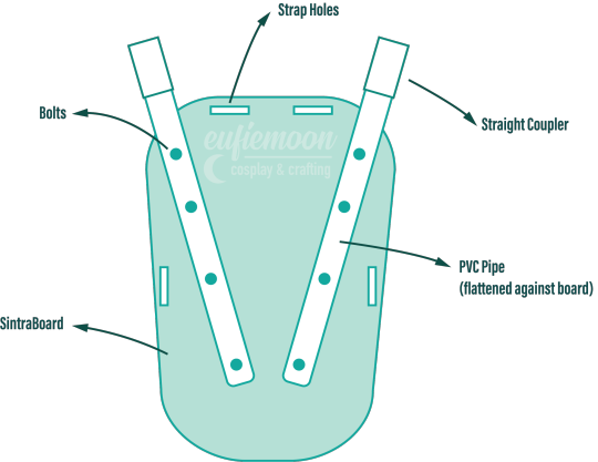
5. I wanted my wings to be relatively modular for ease of travel so I needed to make sure certain portions of them could come away from other parts easily, so I popped a straight coupler on the top of the pipes that were attach to the breastplate, this also meant I could slot the breastplate over these shorter pipes and wear everything correctly! Then these second pipes slot on and at the other end they are attached via hinges to the longest portion of the pipe 'skeleton', Diagram below:
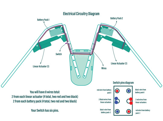
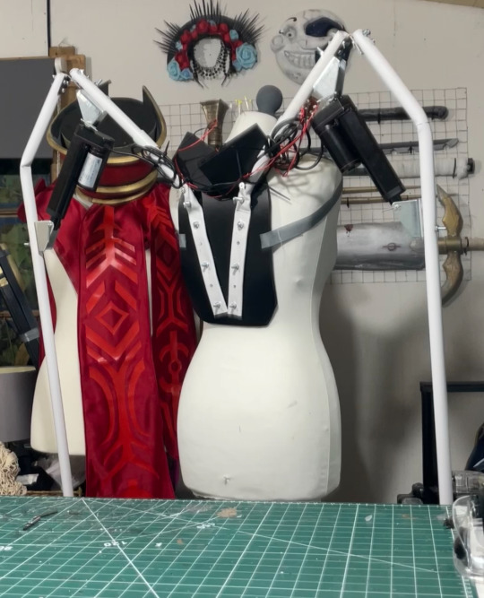
6. Now that the skeleton was put together, it's time for the electrical stuff! It's a good idea to figure out where your circuit is going to lay on the skeleton - consider if you want the battery packs mounted the the backplate or, like me, put them inside the actual wings in removeable pockets for easy access and removal for battery changes. all your wires will go through the switch so deciding where you want to place that is very important! Mine was placed just over my shoulder on the front side, mounted to the PVC pipe with a metal cover I drilled a hole into to slip the switch through and then drill through the pipe.
I've included another diagram below that explains all the electrical circuitry, including which wires go on which pins on the switch!
Important to note: The linear actuators need to be placed and bolted into the PVC pipes at *exactly* the same angle on each side, any slight deviation will lead to the wings going up wonkily! So take your time and make as many adjustments as necessary.
7. You can extend your wires by adding on the electrical wire, just match the colours, and put heat shrink tubing over the connections to hide the live wires! I ended up zip-tying the wires into organised bundles once the wings were done to help keep everything safe from snags.
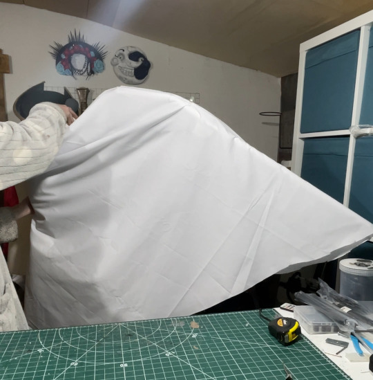
8. Now its time for the Wings themselves! I drafted my base pattern by just draping the white cotton fabric I had over the wing when it was fully extended. I then pinned the wings to the shape I wanted them to be along the bottom before cutting along the pins. I ran the fabric through my sewing machine to close the bottom edge, leaving a gap wide enough by the wing base so I could slip the wing on and off, closing it with velcro. I also added little fabric pockets inside of these to hold my battery packs, which also connected via velcro for easy removal!
9. Now that I had a wing base I was able to begin making feathers! I cut out a total of 800 feathers out of polythene jiffy roll for these wings, in 6 different styles and using real life bird wings to dictate the shapes I used and where I placed them. I ended up hot gluing every individual feather onto the white fabric base, going row by row until every side was covered, the wing covers themselves are super light because of the foam feathers and they shine light through them in a really magical way!

Optional: I also ended up going over these feathers with my airbrush and some super light beige paint to help darken the shadows, this is entirely optional and may change depending on the wings you're looking to make!
When in neutral position and in extended position the wings looks like this:

Mine had a wingspan of about 7ft total when fully extended but when in neutral position they were fairly close to my own proportions! mainly staying behind me and weren't much of a problem in a packed con hall!

Photo by: Helloimfran (on Instagram and Twitter)
I hope this tutorial helped and if there are any questions about anything in specific don't hesitate to reach out at [email protected] or on my instagram or twitter (@eufiemoon)
Happy Crafting!

#cosplay#cosplayer#cosplaying#baldurs gate iii#baldur’s gate 3#baldurs gate 3#bg3#dame aylin#aylin x isobel#bg3 aylin#cosplay tutorial#Wings#fantasy#tutorial#cosplay help#cosplay tips
162 notes
·
View notes
Text
How to Replace the Rear Camera on iPhone 12 Pro Max
The iPhone 12 Pro Max is thought for its brilliant virtual virtual digicam fantastic, especially its superior rear digicam device that consists of huge, extremely-large, and telephoto lenses. But what takes location whilst your digital camera begins offevolved malfunctioning, showing blurry pics, or surely stops working altogether? Whether your phone has suffered bodily harm or a hardware glitch, a rear virtual digital camera possibility is probably your only preference.
The suitable information? You can replace the rear digital camera to your iPhone 12 Pro Max yourself in case you're assured and feature the right gear. With the supply of Phone 12 Pro Max alternative factors on line, getting a ultra-modern rear virtual digital camera module is lots much less tough than ever.
In this blog, we at Elite Cell Parts provide you with all the information that you need to know about the Rear Camera replacement of your iPhone 12 Pro Max. More importantly, we ensure that you understand the process involved in finding iPhone 12 Pro Max replacement parts online.
When Should You Replace the Rear Camera?
We at Elite Cell Parts provide you below with some signs and symptoms that the Rear Camera replacement of your iPhone 12 Pro Max is needed:
The digital camera app shows a black show or maintains crashing
Photos seem blurry or distorted however cleaning the lens
Autofocus or zoom functions not art work
The digital camera fails to open or generates hardware errors messages
Physical harm is seen on the camera lenses
If you are experiencing one or greater of those issues, it might be time for a Rear Camera replacement. Apple renovation can be luxurious, so many customers choose to buy iPhone 12 Pro Max replacemet parts online and do it themselves. Tools and Parts You Will Need
Before you start, make certain you've got the following Rear Camera replacement instruments given below:
Replacement rear digital virtual digital camera module for iPhone 12 Pro Max
Pentalobe screwdriver (for backside screws)
Tri-point screwdriver
Phillips screwdriver
Plastic pry machine
Suction cup
Tweezers
Heat gun or hair drye
ESD-secure gloves or grounding strap (optionally to be had but advocated)
You can find all of those device and iPhone 12 Pro Max replacement parts online from reliable electronics repair ‘E-Stores’ like Elite Cell Parts.
Step-via-Step: How to Replace the Rear Camera:
1. Power Off the Device
Start with the resource of turning off your iPhone truely. This helps save you short circuits or different electric powered damage at some stage in disassembly.
2. Remove the Screws Near the Charging Port
Use the pentalobe screwdriver to do away with the two screws positioned on both aspect of the charging port. These constant the show to the telephone’s frame.
3. Loosen the Display with Heat
Use a warm temperature gun or hair dryer to softly warmth the edges of the show show display screen. This softens the adhesive that holds the show in area, making it much less complex to open.
4. Lift the Screen Carefully
Place a suction cup genuinely above the house indicator line. Gently pull up even as placing a plastic pry tool a number of the show screen and body. Carefully art work your manner round the brink to loosen the display. Be affected character—rushing this step can crack the show.
Once the show is unfastened, carry it from the left side like a ebook, however don’t take away it in reality but. There are flex cables connecting the display to the exceptional judgment board.
5. Disconnect the Battery and Camera Connectors:
Remove the shield plates protecting the connectors the usage of the tri-factor and Phillips screwdrivers. Use plastic tweezers or your fingers to softly disconnect the battery first.
Next, disconnect the front panel display cables and in the long run, the rear virtual digital camera connector.
6. Remove the Rear Camera
With the connector detached, cautiously raise the rear virtual digital camera module out of its compartment. It may additionally have a chunk of adhesive, so gently wiggle it free if desired. Be advantageous no longer to the touch the lenses or internal components.
7. Install the New Rear Camera
Take your new rear virtual camera out of your Phone 12 Pro Max alternative additives online order and insert it into the virtual camera housing. Make wonderful it sits flush and contours up efficaciously with the mounting elements.
Reconnect the digital digital camera flex cable to the best judgment board, ensuring it clicks into vicinity.
8. Reconnect the Display and Battery:
Reconnect the display flex cables and the battery connector. Once all of the cables are connected, screw the defend plates again into region to regular them.
9. Test the Camera Before Sealing the Phone:
Before sealing your tool, strength it on and take a look at the rear digital digital digicam skills:
Open the camera app
Try image and video modes
Test zoom and attention
Switch among huge, extraordinarily-large, and telephoto lenses
If the whole lot works flawlessly, you’re precise to move. If some detail doesn’t paintings, double-test the connectors and strive another time.
10. Seal the Phone and Reinsert Screws
Once you are assured the camera is strolling, lightly press the show again into the body. You may additionally furthermore need to apply a bit of strain round the rims to make sure a very good seal.
Finally, update the two screws close to the charging port the usage of your pentalobe screwdriver. To complete Rear Camera replacement of your iPhone 12 Pro Max.
Tips for a Smooth Rear Camera Replacement:
Always paintings on a clean, static-unfastened surface
Keep track of tiny screws and components using a magnetic mat
Be mild—iPhone internals are touchy
Avoid touching the virtual digicam lenses to save you fingerprints or scratches
Double-check compatibility when ordering Phone 12 Pro Max opportunity factors on line
Where to Find Reliable Phone 12 Pro Max Replacement Parts Online
Not all Rear Camera replacement components for your iPhone 12 Pro Max are created same. When shopping for a current rear digicam module, make certain you select a depended on dealer. Look for:
High client rankings
Detailed element descriptions
Compatibility guarantees
Warranty or bypass back coverage
Sites that specialize in iPhone protection and accessories are normally a more regular wager than popular marketplaces.
Performing a Rear Camera replacement process in your iPhone 12 Pro Max may additionally sound intimidating, however with staying electricity and the right system, it’s honestly viable—even for beginners. Whether you are attempting to restore a malfunctioning digicam or carry a damaged tool back to lifestyles, buying Phone 12 Pro Max alternative factors online gives you an cheaper and powerful answer.
So next time your rear virtual digital camera stops cooperating, don’t panic—visit Elite Cell Parts to get high-quality iPhone 12 Pro Max replacemet parts online at affordable pricing.
Got questions or want assistance in getting iPhone 12 Pro Max replacemet parts online done to perfection? Drop a remark beneath—we are here to assist you in performing a Rear Camera replacement process effectively.
0 notes
Text
Absolute EMS and the Evolution of Next-Gen PCB Assembly Services
The assembly of electronics is a vast, evolving field, filled with challenges. Automation has sparked a quiet revolution in the industry, and it continues to shift in that direction. Within this constantly changing horizon of electronics assembly - precision, reliability, and efficiency drive advancement. Absolute EMS, a leader in PCB Assembly Services (PCBA or EMS), offers cutting-edge assembly solutions to demanding high-performance OEMSs. Their technological expertise in press-fit connectors in silicon valley guarantees a strong interconnect without the inconveniences inherent in conventional soldering.

The Engineering Behind Press-Fit Connectors
Press-fit connectors are a replacement for conventional soldered connections, providing a very reliable mechanical and electrical interface. The connector pins have compliant sections that form a gas-tight joint when pressed into plated through-holes (PTHs) of a PCB. The process provides:
Uniform Contact Pressure: Uniform pressure inside the hole is delivered through elastic deformation of the flexible pin, keeping the micro-movements low and signal attenuation low.
Elimination of Soldering Defects: Defects such as cold joints, solder bridges, and thermal stress are fully eliminated.
Superior Mechanical Retention: High insertion pressure and frictional locking avoid removal by shock and vibration.
Improved High-Frequency Signal Integrity: The uniform contact resistance minimizes electromagnetic interference (EMI) and ensures reliable data transmission in RF and high-speed digital circuits.
Complementary High-Precision PCB Assembly Techniques
Absolute EMS also integrates other cutting-edge methodologies in PCB assembly, ensuring adherence to stringent industry standards such as IPC Class 3 for high-reliability applications. These capabilities include:
High-Density Surface Mount Technology (SMT): Advanced pick-and-place systems handle micro-BGAs, fine-pitch QFNs, and 01005 components for compact, high-performance designs. And large BGA (4k+ balls) pick and place.
Selective Through-Hole Technology (THT): Precision-controlled soldering techniques, including wave soldering and selective soldering, enhance the integrity of mechanical and power connections without disturbing other components on the board..
Hybrid Assembly Solutions: A combination of SMT and PTH and that enables complex multi-layer PCB configurations suited for demanding applications.
Automated Optical Inspection (AOI)and X-Ray Inspection: Ensuring defect-free assembly through real-time analysis and verification of solder joints, component placement, and internal structure.
Final Thoughts
For companies looking for Electronic Manufacturing Services , Absolute EMS provides specialized solutions in press-fit connectors, based in Silicon Valley. They constantly strive to deliver the best technology and their dedication to quality, efficiency, and technology makes them a go-to partner for all the high tech OEMS in Silicon Valley and beyond.
To see their entire range of PCB assembly services, contact Absolute EMS and learn how they can get your product to market faster with their electronic manufacturing processes.
0 notes
Text
The Advantages and Applications of Flexible PCB in Modern Electronics
Introduction
The electronics industry is constantly evolving, and one of the most significant advancements in recent years has been the widespread adoption of Flexible PCB (Printed Circuit Board) technology. Unlike traditional rigid PCBs, Flexible PCB offers unparalleled adaptability, making it ideal for modern compact and high-performance devices. From consumer electronics to medical equipment, Flexible PCB has revolutionized how circuits are designed and implemented.
This article explores the benefits, applications, and future trends of Flexible PCB, highlighting why it has become a cornerstone of innovation in electronics.
What is a Flexible PCB?
A Flexible PCB is a type of printed circuit board made from flexible materials such as polyimide or polyester. Unlike rigid PCBs, which use fiberglass, Flexible PCB can bend, twist, and fold without breaking, enabling more versatile designs.
Key Components of a Flexible PCB
Substrate Material – Typically polyimide, known for its heat resistance and flexibility.
Conductive Layers – Copper traces that form the electrical pathways.
Protective Coating – A coverlay or solder mask to shield the circuits from damage.
Adhesives – Used to bond layers together while maintaining flexibility.
Advantages of Flexible PCB
1. Space and Weight Reduction
One of the biggest advantages of Flexible PCB is its ability to fit into tight spaces. Since it can bend and conform to different shapes, it eliminates the need for bulky connectors and wiring, reducing both size and weight. This makes it perfect for smartphones, wearables, and aerospace applications.
2. Enhanced Durability
Flexible PCB can withstand vibrations, shocks, and repeated bending, making it more durable than rigid PCBs. This is particularly useful in automotive and industrial applications where reliability is critical.
3. Improved Signal Integrity
With fewer interconnects and shorter signal paths, Flexible PCB reduces electromagnetic interference (EMI) and signal loss. This is essential for high-frequency applications like 5G devices and advanced medical imaging systems.
4. Cost-Effective Assembly
Although Flexible PCB may have higher initial material costs, it simplifies assembly by reducing the need for connectors and additional wiring. This leads to lower labor costs and improved production efficiency.
5. Thermal Management
Polyimide-based Flexible PCB can handle high temperatures, making them suitable for applications where heat dissipation is crucial, such as LED lighting and power electronics.
Applications of Flexible PCB
1. Consumer Electronics
Flexible PCB is widely used in smartphones, tablets, and laptops, enabling slimmer designs and foldable screens. Companies like Samsung and Apple rely on Flexible PCB for their cutting-edge devices.
2. Medical Devices
In the medical field, Flexible PCB is used in wearable health monitors, implantable devices, and diagnostic equipment. Its lightweight and biocompatible properties make it ideal for patient-friendly solutions.
3. Automotive Industry
Modern vehicles incorporate Flexible PCB in dashboard displays, sensors, and lighting systems. Its ability to endure harsh environments ensures long-term performance.
4. Aerospace and Defense
Flexible PCB is crucial in satellites, drones, and military equipment due to its lightweight nature and resistance to extreme conditions.
5. Industrial Automation
Robotics and industrial machines use Flexible PCB for reliable signal transmission in dynamic and high-stress environments.
Future Trends in Flexible PCB Technology
1. Stretchable Electronics
Researchers are developing stretchable Flexible PCB that can expand and contract, opening new possibilities for wearable tech and biomedical applications.
2. Integration with IoT
As the Internet of Things (IoT) grows, Flexible PCB will play a key role in connecting smart devices with minimal space requirements.
3. 3D Printed Flexible Circuits
Advancements in 3D printing may allow for custom Flexible PCB designs with even greater complexity and efficiency.
4. Eco-Friendly Materials
Sustainable Flexible PCB materials, such as biodegradable polymers, are being explored to reduce electronic waste.
Conclusion
The rise of Flexible PCB has transformed the electronics industry by offering unmatched flexibility, durability, and efficiency. From smartphones to space technology, its applications are vast and continually expanding. As innovation progresses, Flexible PCB will remain at the forefront of electronic design, enabling smarter, lighter, and more resilient devices.
For engineers and manufacturers, adopting Flexible PCB technology is not just an option—it’s a necessity for staying competitive in a rapidly evolving market.
1 note
·
View note
Text
Flexible PCB Manufacturer: The Key to Advanced Electronics Innovation
Introduction
The electronics industry is rapidly evolving, and Flexible PCB Manufacturer plays a crucial role in enabling cutting-edge innovations. From wearable devices to aerospace applications, flexible printed circuit boards (PCBs) provide unmatched adaptability, durability, and performance. This article explores the importance of flexible PCBs, their manufacturing process, applications, and how choosing the right Flexible PCB Manufacturer can make a significant difference in product development.
What Are Flexible PCBs?
Flexible PCBs are circuit boards made from bendable materials such as polyimide or polyester. Unlike rigid PCBs, they can twist, fold, and conform to unique shapes, making them ideal for modern electronics where space and weight are critical factors.
Key Advantages of Flexible PCBs
Space Efficiency – Their thin and lightweight design allows for compact electronic assemblies.
Durability – Resistant to vibrations and mechanical stress, making them suitable for harsh environments.
High Performance – Excellent thermal stability and signal integrity for high-frequency applications.
Cost-Effective Assembly – Reduces the need for connectors and additional wiring, lowering production costs.
The Role of a Reliable Flexible PCB Manufacturer
Choosing the right Flexible PCB Manufacturer is essential for ensuring quality, reliability, and performance. A reputable manufacturer will offer:
1. Advanced Manufacturing Techniques
A top-tier Flexible PCB Manufacturer utilizes cutting-edge processes such as:
Laser Drilling – Ensures precision in microvia formation.
Automated Optical Inspection (AOI) – Detects defects early in production.
High-Density Interconnect (HDI) Technology – Enables complex, multi-layer flexible circuits.
2. Material Expertise
The best manufacturers work with high-quality materials, including:
Polyimide Films – Known for heat resistance and flexibility.
Copper Foils – Provides excellent conductivity.
Adhesive Systems – Ensures strong bonding between layers.
3. Customization Capabilities
A skilled Flexible PCB Manufacturer can tailor designs to meet specific requirements, such as:
Dynamic Flex Circuits – For repeated bending applications.
Rigid-Flex PCBs – Combines rigid and flexible sections for complex assemblies.
High-Frequency Flexible PCBs – Optimized for RF and microwave applications.
Applications of Flexible PCBs
Flexible PCBs are used in a wide range of industries due to their versatility.
1. Consumer Electronics
Smartphones & Tablets – Enables slim designs and foldable screens.
Wearable Devices – Used in smartwatches and fitness trackers for comfort and flexibility.
2. Medical Devices
Implantable Devices – Flexible circuits are biocompatible and durable.
Diagnostic Equipment – Supports high-precision sensors and compact designs.
3. Automotive Industry
Electric Vehicles (EVs) – Used in battery management systems and LED lighting.
Advanced Driver Assistance Systems (ADAS) – Ensures reliable performance in tight spaces.
4. Aerospace & Defense
Satellites & UAVs – Lightweight and resistant to extreme conditions.
Military Communication Systems – Provides high reliability in mission-critical applications.
How to Choose the Best Flexible PCB Manufacturer
Selecting the right Flexible PCB Manufacturer involves evaluating several factors:
1. Experience & Reputation
Look for manufacturers with a proven track record in flexible PCB production. Customer reviews and industry certifications (e.g., ISO 9001, IPC standards) are good indicators of reliability.
2. Technical Support & Design Assistance
A top Flexible PCB Manufacturer offers design-for-manufacturability (DFM) feedback to optimize performance and reduce costs.
3. Quality Control & Testing
Ensure the manufacturer follows strict quality checks, including:
Electrical Testing – Verifies circuit functionality.
Environmental Testing – Assesses performance under stress conditions.
4. Scalability & Lead Times
Whether you need prototypes or mass production, the manufacturer should offer flexible solutions with reasonable turnaround times.
Future Trends in Flexible PCB Manufacturing
The demand for flexible PCBs continues to grow, driven by innovations such as:
Foldable & Rollable Displays – Expanding possibilities in consumer electronics.
Internet of Things (IoT) Devices – Requires compact, high-performance circuitry.
5G Technology – Flexible PCBs support high-frequency signal transmission.
As technology advances, partnering with a forward-thinking Flexible PCB Manufacturer will be crucial for staying competitive.
Conclusion
Flexible PCBs are revolutionizing electronics with their adaptability and performance. Choosing the right Flexible PCB Manufacturer ensures high-quality production, innovative solutions, and reliable end products. Whether for consumer gadgets, medical devices, or aerospace applications, flexible PCBs are paving the way for the next generation of electronic advancements.
By understanding manufacturing processes, material choices, and industry applications, businesses can make informed decisions when selecting a Flexible PCB Manufacturer to bring their innovative designs to life.
1 note
·
View note
Text
What is Circuit Card Assembly, and How Does it Relate to PCB Board Assembly?
Circuit Card Assembly (CCA) is a basic step in the gadgets manufacturing prepare that includes the development and assembly of electronic circuits onto a circuit card, commonly alluded to as a Printed Circuit Board (PCB). This handle shapes the spine of cutting edge electronic gadgets, from shrewd phones to restorative hardware, guaranteeing that components are associated, useful, and dependable. Whereas it offers similarities with PCB Board Assembly, there are unmistakable contrasts that make each term imperative in understanding the whole prepare of electronic item development.
Understanding Circuit Card Assembly (CCA)
Circuit Card Assembly (CCA) alludes to the comprehensive prepare of Assembly all the electronic components onto a printed circuit board. This regularly incorporates setting and patching components such as resistors, capacitors, microchips, and connectors onto the PCB surface. Once these components are patched in place, the board experiences testing to guarantee that it capacities as intended.
In the CCA prepare, a few vital steps take put, including:
1. Component Arrangement: Electronic components are set onto the PCB, more often than not utilizing a pick-and-place machine, which guarantees exact and productive situation of indeed the littlest components.
2. Soldering: The components are at that point patched to the board utilizing either a wave patching handle (for through-hole components) or reflow fastening (for surface-mount components).
3. Inspection and Testing: After the patching handle, the amassed circuit card experiences different review forms such as Automated Optical Inspection (AOI) and Electrical Testing to guarantee the associations are strong and there are no faults.
4. Final Assembly: Once the CCA is completely gathered and tried, it may be coordinates into a last item or experience extra forms, like embodiment or housing.
Circuit Card Assembly is pivotal since it guarantees that the PCB can perform the vital electrical capacities for the gadget its planned for. Without legitimate Assembly, the PCB board may fall flat to provide control or information to the components of the gadget, rendering the whole framework inoperative.
What is PCB Board Assembly?
PCB Board Assembly alludes to the broader handle of mounting electronic components onto a PCB, making it competent of facilitating the required electrical associations. Whereas PCB Board Assembly can be seen as a broader term, it frequently includes comparative forms to Circuit Card Assembly, counting patching, component arrangement, and testing. Basically, PCB Board Assembly is the system for the creation of a useful Circuit Card Assembly.
However, one key qualification between the two is that PCB Board Assembly regularly alludes to the Assembly of the board itself, whereas Circuit Card Assembly centres more particularly on the components that are put and patched onto the PCB.

How Does Circuit Card Assembly Relate to PCB Board Assembly?
The relationship between Circuit Card Assembly and PCB Board Assembly is both coherent and basic. PCB Board Assembly serves as the establishment on which the Circuit Card Assembly takes put. Without a legitimately collected PCB board, there would be no stage to mount and interface the electronic components.
In other words, PCB Board Assembly makes the physical framework of the PCB, giving the essential copper follows and cushions that will afterward serve as pathways for electrical current. Once this is done, Circuit Card Assembly takes over to put the components, patch them, and guarantee that the circuit performs as needed.
A PCBA Circuit Board (Printed Circuit Board Assembly) is the wrapped up item that comes about from the combination of PCB Board Assembly and Circuit Card Assembly. It is a completely amassed and useful circuit card that incorporates all the vital components and electrical associations. This coordinates, gathered PCB is the heart of about each electronic gadget, from customer contraptions to mechanical machinery.
Conclusion
In conclusion, whereas Circuit Card Assembly and PCB Board Assembly are related forms, they centre on diverse stages of the manufacturing of a PCBA Circuit Board. PCB Board Assembly is the foundational handle that makes the board, whereas Circuit Card Assembly is the detailed work of putting and fastening the components onto that board. Together, they guarantee the usefulness and unwavering quality of the PCBA Circuit Board, which is fundamentally to any advanced electronic gadget. Understanding these forms is basic for anybody included in the generation of electronic items, as each step plays a significant part in guaranteeing the last product’s execution and quality.
0 notes
Text
Top 10 Electrical Accessories Manufacturers
In the rapidly evolving electrical industry, choosing the right electrical accessories manufacturer is crucial for ensuring safety, efficiency, and long-term performance. From switches and sockets to advanced cable management systems, electrical accessories play a vital role in any electrical installation. Whether you’re a contractor, a homeowner, or a business, partnering with a reliable manufacturer can make a significant difference.
Here’s a look at the top 10 electrical accessories manufacturer in the market today, known for their expertise, innovative designs, and commitment to quality.
1. Asio World
Asio World, a leader in the field of electrical accessories manufacturing, sets a high standard for products that combine advanced technology with durability. Known for their exceptional quality and customer-centric approach, Asio World manufactures a wide range of products that cater to both industrial and domestic applications. They are a preferred choice for businesses and households alike, offering solutions that are both reliable and cost-effective.
Their electrical accessories include everything from circuit breakers and cables to connectors and switches, all built with the highest safety standards in mind. Asio Electrical's commitment to innovation ensures that its products meet the evolving needs of the electrical industry, making it an excellent choice for any project.
Visit their website: Asio Electricals

2. Schneider Electric
Schneider Electric is one of the most trusted names in electrical equipment and accessories. As a global specialist in energy management and automation, Schneider Electric offers a broad range of electrical accessories that are designed for both commercial and residential sectors. Their products are known for their energy efficiency, reliability, and sustainable design.
Schneider Electric’s range of electrical accessories includes switches, sockets, power distribution units, and intelligent home solutions. Their focus on innovation ensures that their products are future-ready, catering to the needs of modern electrical installations.
3. Legrand
Legrand is a globally recognized manufacturer of electrical and digital building infrastructures. Their electrical accessories are known for their modern designs, advanced functionality, and compliance with global safety standards. Legrand offers a variety of products, including wiring devices, circuit breakers, and cable management systems.
With a strong focus on sustainability and energy efficiency, Legrand's electrical accessories are engineered to provide long-lasting performance and reliability. Their user-friendly designs also make them a favorite among both residential and commercial customers.
4. Havells
Havells is one of India's leading electrical brands, offering a wide range of electrical accessories and solutions for residential, commercial, and industrial use. The company’s products are known for their high quality and innovation, which are backed by years of expertise in the electrical industry.
Havells' electrical accessories include switches, lighting controls, and cables that adhere to international safety standards. The company is constantly innovating to meet the growing demands of the electrical industry, making them a trusted partner for electrical contractors and businesses.
5. Siemens
Siemens is a well-established name in the electrical industry, offering a comprehensive range of electrical accessories. Siemens’ products are known for their exceptional quality, durability, and cutting-edge technology. The company manufactures a wide array of electrical components, including switches, sockets, transformers, and distribution boards.
Siemens is a global leader in automation and electrification, ensuring that their electrical accessories are equipped with the latest features and technology. Their products are designed to maximize energy efficiency and reduce operational costs.
6. ABB
ABB is another global powerhouse in electrical accessories manufacturing, providing a vast range of solutions for power distribution and electrical systems. ABB’s products are recognized for their high performance and safety standards.
Their electrical accessories, such as circuit breakers, transformers, and disconnectors, are designed to meet the stringent demands of both industrial and residential applications. ABB is committed to sustainability, ensuring that its products help reduce environmental impact while maintaining top-notch performance.
7. MK Electric
MK Electric is known for offering some of the most reliable and durable electrical accessories in the market. The brand is trusted for producing high-quality wiring devices, such as switches, sockets, and junction boxes, as well as advanced cable management systems.
MK Electric emphasizes quality, design, and safety in all its products, ensuring that customers receive top-tier performance and aesthetic appeal. Their electrical accessories are ideal for both residential and commercial applications.
8. Bajaj Electricals
Bajaj Electricals offers a wide range of electrical accessories, including fans, lights, switches, and other electrical components. The company has built a strong reputation for quality and customer satisfaction, with products that cater to both individual consumers and businesses.
Bajaj Electricals’ products are known for their reliability, energy efficiency, and modern designs, making them a top choice for anyone looking for long-lasting electrical accessories.
9. V-Guard
V-Guard is a trusted name in the electrical accessories industry, particularly known for its electrical cables, stabilizers, and switches. The company’s products are built to meet high standards of safety and performance, ensuring reliable operation even in challenging environments.
V-Guard is constantly evolving to provide innovative solutions for the electrical sector, making it a strong competitor in the market.
10. Philips
Philips is a global leader in lighting and electrical accessories, providing products that are designed for both residential and commercial use. Their range of products includes everything from smart lighting systems to switches and power cords.
Philips’ commitment to energy efficiency and innovation ensures that their electrical accessories deliver superior performance while minimizing environmental impact. The company’s strong brand reputation makes it a top choice for electrical solutions worldwide.
Conclusion
The electrical accessories industry is vast, with many manufacturers offering innovative solutions that cater to various needs. Asio Electricals, with its extensive range of high-quality products, stands out as a leader in the industry, providing reliable, cost-effective, and safe electrical accessories for all types of installations. Their website, Asio Electricals, is the perfect place to explore their range of products and learn more about how they can support your electrical needs.By partnering with trusted brands like Asio Electricals, you can ensure that your electrical systems are built to last, safe to use, and optimized for energy efficiency. Choose wisely, and make the right choice for your electrical projects.
Also Read:
What Are Conduit Pipe Fittings? A Comprehensive Guide
40A Double Pole MCB: A Cost-Effective Solution for Your Electrical Needs
0 notes
Text
Salt Spray Chamber The Key to Effective Corrosion Testing
Introduction
Corrosion can significantly impact the lifespan and performance of metals and coatings. To prevent premature deterioration, industries rely on Salt Spray Chambers for accurate corrosion resistance testing. Pacorr.com offers advanced Salt Spray Test Chamber, ensuring reliable and efficient material evaluation.

What is a Salt Spray Chamber?
A Salt Spray Chamber (or Salt Fog Test Chamber) simulates harsh environmental conditions to test material durability. It generates a saltwater mist (typically 5% NaCl), exposing materials to accelerated corrosion, helping manufacturers assess their protective coatings, galvanized layers, and painted surfaces.
Industries That Use Salt Spray Chambers
1. Automotive Industry
Evaluates corrosion resistance of body panels, fasteners, and coatings.
Ensures durability of painted and electroplated vehicle components.
2. Aerospace & Aviation
Tests aircraft fasteners, connectors, and aluminum parts.
Ensures protective coatings withstand extreme conditions.
3. Marine Industry
Verifies corrosion resistance of ship components and offshore structures.
Evaluates anchors, propellers, and naval equipment for durability.
4. Electronics & Electrical Industry
Tests circuit boards, connectors, and enclosures for corrosion resistance.
Ensures reliability of components exposed to humid environments.
5. Paint & Coatings Industry
Examines adhesion strength and corrosion protection of powder coatings and metal finishes.
Ensures industrial coatings maintain integrity under extreme conditions.
Why Choose Pacorr’s Salt Spray Chambers?
At Pacorr.com, we provide cutting-edge Salt Spray Chamber with the following features:
✅ High-Quality Construction – Made from FRP or stainless steel for durability. ✅ Uniform Salt Mist Distribution – Advanced atomization for precise testing. ✅ Digital Control System – Easy-to-use programmable settings. ✅ Accurate Temperature & Humidity Control – Ensures stable test conditions. ✅ Compliance with International Standards – Meets ASTM B117, ISO 9227, JIS Z 2371.
Benefits of a Salt Spray Chamber
✔ Accelerated Corrosion Testing – Simulates years of exposure in days. ✔ Enhances Product Quality – Helps improve coating and metal durability. ✔ Cost-Effective – Reduces the need for real-world field testing. ✔ Reliable & Repeatable Results – Ensures consistent performance evaluations.
Conclusion
A Salt Spray Chamber Price is a crucial tool for industries requiring corrosion-resistant materials and coatings. With Pacorr’s high-performance chambers, manufacturers can improve product durability, meet quality standards, and enhance reliability.
🔹 Explore our Salt Spray Testing Solutions at Pacorr.com!
0 notes
Text
Multilayer Flex Circuits: Advanced Solutions for Complex Electronics
Multilayer flex circuits, also known as multilayer flexible printed circuits (FPCs), represent the pinnacle of flexible circuit technology. By combining multiple layers of conductive material in a flexible form, multilayer flex circuits provide an exceptional solution for high-performance, compact, and reliable electronics. These circuits are widely used in various industries where flexibility, high-density interconnects, and space optimization are crucial.
In this blog, we explore what multilayer flex circuits are, their advantages, applications, and why they are becoming increasingly popular in cutting-edge electronics design.
What Are Multilayer Flex Circuits? : MultilayerFlex Circuits
Multilayer flex circuits are flexible printed circuit boards (PCBs) that incorporate more than one layer of conductive traces to create a complex, high-density circuit. These circuits typically consist of multiple layers of flexible base materials, such as polyimide, which are bonded together with inner conductive layers like copper. The conductive traces on each layer are connected using vias (tiny holes that allow electrical connections between the layers), creating a compact and flexible circuit that can handle complex designs.
The key feature of multilayer flex circuits is that they offer multiple layers of electrical interconnections while maintaining the flexibility needed for applications where bending, folding, or compact form factors are essential.
Key Characteristics of Multilayer Flex Circuits : Multilayer Flex Circuits
Multiple Layers of Conductive MaterialMultilayer flex circuits can incorporate anywhere from two to several layers of conductive traces, each carefully designed to carry electrical signals or power. This multi-layer structure allows for high-density interconnections in a compact space.
FlexibilityThe core advantage of flex circuits is their ability to bend, twist, and fold without breaking. This flexibility makes multilayer flex circuits ideal for use in small, intricate, and often dynamic applications where traditional rigid PCBs would not fit.
High-Density Interconnections (HDI)Multilayer flex circuits enable the creation of high-density interconnects, which means more components can be placed on a smaller footprint. This is crucial for modern electronics that require significant functionality in a small, space-constrained design.
Lightweight and CompactMultilayer flex circuits are typically lighter and more compact than their rigid counterparts. They can save space in devices by eliminating the need for connectors, multiple boards, or wiring, leading to more efficient designs.
DurabilityThese circuits are designed to withstand mechanical stress, heat, and environmental factors. The materials used in multilayer flex circuits, such as polyimide, offer excellent thermal and chemical resistance, ensuring long-term performance in demanding conditions.
Advantages of Multilayer Flex Circuits : Multilayer Flex Circuits
Space and Weight SavingsOne of the most significant benefits of multilayer flex circuits is their ability to save both space and weight. These circuits can integrate multiple connections and components into a single compact design, making them perfect for small or portable devices, including wearables, smartphones, and medical devices.
Increased ReliabilityWith fewer connectors and components needed, multilayer flex circuits reduce the chances of connection failures or signal loss, improving the overall reliability of the device. The absence of solder joints and the use of fewer interconnects results in fewer points of failure.
Design FlexibilityThe flexibility of multilayer flex circuits allows for more creative and innovative designs. They can be bent or shaped to fit within unique form factors, such as conforming to curved surfaces or fitting into tight spaces without sacrificing electrical performance.
Improved PerformanceBy using multiple layers to route electrical signals and power, multilayer flex circuits improve signal integrity and reduce the chances of signal interference. Their high-density interconnects also support higher data rates, making them suitable for high-performance applications.
Reduced Assembly ComplexityMultilayer flex circuits reduce the need for separate boards and connectors, streamlining the assembly process and reducing the overall number of parts in a system. This can result in lower overall production costs and faster time-to-market.
Applications of Multilayer Flex Circuits : Multilayer Flex Circuits
Consumer ElectronicsMultilayer flex circuits are commonly found in consumer electronics like smartphones, laptops, tablets, and wearable devices (smartwatches, fitness trackers). Their small size, flexibility, and high-density interconnects make them ideal for devices that require a lot of functionality in a small, compact form factor.
Medical DevicesMedical devices, including diagnostic equipment, monitoring systems, and implantable devices, benefit from multilayer flex circuits' compactness and reliability. These circuits can be designed to fit in limited spaces while still providing the performance needed for sensitive medical applications.
Aerospace and DefenseMultilayer flex circuits are crucial in aerospace and defense systems where high-performance electronics must withstand harsh environmental conditions, such as extreme temperatures, vibrations, and radiation. They are used in satellite systems, avionics, and military communication devices.
AutomotiveThe automotive industry uses multilayer flex circuits in advanced driver-assistance systems (ADAS), infotainment systems, and electronic control units (ECUs). Their ability to perform reliably in high-stress, high-vibration environments makes them suitable for automotive applications.
Industrial EquipmentIn industrial settings, multilayer flex circuits are used in machinery control systems, robotics, and automation. These circuits' flexibility allows them to be used in a variety of form factors, ensuring seamless integration into complex systems.
Challenges of Multilayer Flex Circuits : Multilayer Flex Circuits
Higher Manufacturing Cost
Due to the complexity of manufacturing and the use of multiple layers, multilayer flex circuits can be more expensive to produce than single-layer flexible circuits or traditional rigid PCBs. However, their long-term benefits often justify the higher upfront costs.
Design ComplexityDesigning multilayer flex circuits requires careful planning, as routing the connections through multiple layers without compromising performance can be complex. The design must take into account the bending radius, layer bonding, and other factors to ensure the circuit will function as intended.
Limited Bend RadiusWhile flexible circuits can bend, multilayer designs have certain limitations in terms of how tightly they can be bent. Exceeding the recommended bend radius can lead to cracking or damage to the circuit, so designers must ensure proper design considerations are made.
Thermal ManagementMultilayer flex circuits can generate heat, and effectively managing heat dissipation becomes more challenging as the circuit density increases. Careful material selection and design strategies are needed to ensure that thermal issues do not compromise the circuit’s performance.
Conclusion
Multilayer flex circuits represent an advanced solution for modern electronics design, offering the perfect combination of flexibility, compactness, and high-performance capabilities. These circuits are ideal for applications that require a high-density interconnect, space optimization, and durability in dynamic environments.
As industries continue to push the boundaries of innovation, multilayer flex circuits will play a crucial role in enabling more sophisticated, compact, and reliable electronic devices. Whether it's in consumer electronics, medical equipment, automotive, or aerospace applications, multilayer flex circuits are becoming an essential component in the next generation of electronics.
0 notes
Text
https://www.futureelectronics.com/p/interconnect--pin-and-socket-connectors--crimp-terminals/2-520102-2-te-connectivity-1904077
Pin Through Hole Coin Cell Holder, Circular Connectors, Socket receptacle
Ultra Fast 22-18 AWG Straight Fully Insulated Receptacle Assembly
#TE Connectivity#2-520102-2#Connectors#Pin and Socket Connectors#Pin Contacts#Pin Through Hole Coin Cell Holder#receptacle socket#Electrical circuit#Board mount connector#edge connector#Crimp Terminals#Socket mount wire
1 note
·
View note
Text

Applications of CNC Rotary Tables in Various Industries [Infographic]
CNC rotary tables have become indispensable in modern manufacturing. They enhance the capabilities of CNC machines by adding an additional axis of movement. These versatile tools play a pivotal role in improving precision, efficiency, and flexibility across various industries. Below, we explore the key applications of CNC rotary tables and how they contribute to diverse sectors.
1. Aerospace Industry
In the aerospace industry, precision is non-negotiable. CNC rotary tables are used to machine complex components such as turbine blades, engine parts, and structural elements. Their ability to handle intricate geometries and maintain tight tolerances ensures the production of reliable and high-performance aerospace components. The rotary table's multi-axis capabilities allow manufacturers to achieve precision milling, drilling, and contouring, meeting the stringent requirements of aerospace engineering.
2. Automotive Industry
The automotive sector relies heavily on CNC rotary table for producing gears, camshafts, and other critical engine parts. These tables enable manufacturers to perform high-precision machining, ensuring consistency and quality in mass production. Additionally, their use in the creation of custom automotive components supports the growing demand for electric vehicles (EVs) and other innovations in the industry.
3. Medical Device Manufacturing
CNC rotary tables are essential in the medical industry for fabricating intricate components like surgical instruments, orthopedic implants, and prosthetics. The rotary table's high precision allows for the creation of small, complex parts that meet the strict regulatory standards of the healthcare sector. Moreover, their versatility enables manufacturers to work with a variety of materials, including stainless steel, titanium, and specialized medical-grade alloys.
4. Energy Sector
From wind turbines to oil and gas equipment, the energy sector benefits from the capabilities of CNC rotary tables. These tools are used to produce large, heavy-duty components such as flanges, rotors, and pipe connectors. Their robust construction and precise movement ensure reliable performance even in demanding applications, making them a vital asset in energy production and distribution.
5. Tool and Die Manufacturing
The tool and die industry relies on CNC rotary tables for creating molds, dies, and other specialized tools. These components often require intricate details and high accuracy, which rotary tables provide. By enabling simultaneous multi-axis machining, they help manufacturers reduce production time and achieve superior surface finishes.
6. Electronics and Semiconductor Industry
Miniaturization and precision are essential in the electronics sector. CNC rotary tables are used to machine micro-components for semiconductors, circuit boards, and other electronic devices. Their capability to handle small-scale, high-precision tasks ensures optimal performance in the production of cutting-edge electronic equipment.
7. Jewelry and Watchmaking
Artisans in the jewelry and watchmaking industries use CNC rotary tables to craft intricate designs and detailed engravings. These tables enable precise machining of precious metals, ensuring consistency and quality in luxury products. The ability to achieve complex patterns and fine details makes rotary tables invaluable in these highly specialized fields.
Benefits of CNC Rotary Tables
Enhanced Precision: Ideal for applications requiring tight tolerances.
Increased Efficiency: Reduces production time by enabling multi-axis machining.
Versatility: Suitable for various materials and industries.
Cost-Effectiveness: Streamlines production processes, minimizing waste.
Also Read: 4 Benefits of Using Industrial CNC Rotary Table From China
Conclusion
CNC rotary tables are a cornerstone of modern manufacturing, enabling industries to achieve unparalleled precision and efficiency. From aerospace and automotive to medical and electronics, these tools are instrumental in driving innovation and meeting the demands of a competitive market.
Explore the advanced CNC rotary tables from SilverCNC and discover how they can elevate your manufacturing processes. Whether you need precision, versatility, or efficiency, SilverCNC offers solutions tailored to your industry’s unique requirements.
To read more information visit https://tinyurl.com/yk3b7spt and call now at +86 180 9892 0890 or email us at [email protected]
0 notes
Video
youtube
Macbook Air A2681 2022 broken screen repair Hamilton New Zealand | Full Repair Guide applefix & tech engineers call 078394111 or visit 937 victoria street hamilton new zeland
MacBook Broken screen repair Hamilton New Zealand
Macbook Broken Screen repair Experts In Hamilton New Zealand AppleFix & Tech engineers Call 078394111 or visit 937 Victoria Street Hamilton New Zealand. Macbook Air M2 Cracked screen repair full tutorial. Macbook Air 2020 screen replacement general guide
Vertical Lines on the macbook LCD screen? Macbook Screen is broken
Replacing the screen on a MacBook A2681 (which is part of the MacBook Pro 14-inch model, likely released in 2021 or later) requires a precise process, as Apple devices are known for their compact, intricate design. Below is a general guide on how to replace the screen, but keep in mind that it’s crucial to have the right tools and the necessary replacement parts. Tools and Equipment Needed: Pentalobe screwdrivers Tri-point screwdrivers Suction handle or tool Plastic opening tools Spudger ESD-safe tweezers New screen replacement part Anti-static wristband (optional, but recommended) Step-by-Step Guide: 1. Power Off and Disconnect the Battery Shut down the MacBook completely. Unplug any connected peripherals or power cables. If possible, disconnect the battery to prevent any accidental power on during the repair (though this step may not be necessary for all models, it’s a good practice). 2. Remove the Bottom Case Use a Pentalobe screwdriver (P5) to remove the screws around the bottom of the MacBook. Once all the screws are out, gently pry open the bottom case using a plastic opening tool. Be careful not to damage the case or the internal components. 3. Disconnect the Battery Inside the MacBook, locate the battery connector and use a spudger or plastic tool to disconnect it from the logic board. This step ensures that you won’t cause any electrical shorts or damage during the screen replacement. 4. Remove the Broken Screen Place the MacBook on a flat surface. You will need to remove the screws that hold the screen in place. These are typically located around the hinges and the edges of the MacBook. Use the appropriate screwdriver (likely a Pentalobe or Tri-point) to unscrew the screws. Once the screws are removed, use a suction cup or handle to carefully lift the display assembly. If necessary, use a plastic opening tool to gently separate the screen from the case. Be very gentle, as there are thin cables connected to the screen. 5. Disconnect the Display Cables After lifting the screen assembly, you will see the display cables that connect the screen to the logic board. Carefully disconnect these cables by lifting the connectors with a spudger or tweezers. Be extra cautious not to damage the delicate cables. 6. Remove the Old Screen Assembly Once all cables are disconnected, carefully remove the old screen from the laptop body. Set it aside, as you will need to install the new screen. 7. Prepare the New Screen Unbox the new screen carefully and make sure it is the correct part for your MacBook model (A2681). Check the new screen for any protective films or packaging that might need to be removed. 8. Install the New Screen Connect the display cables of the new screen to the logic board, ensuring the connections are secure. Be very gentle to avoid damaging the connectors. Once connected, place the new screen assembly in the proper position and align it with the hinges and mounting points. 9. Secure the Screen Use the screws you removed earlier to secure the new screen to the MacBook. Tighten them carefully, but avoid overtightening to prevent damaging the threads. 10. Reconnect the Battery Once the screen is in place, reconnect the battery connector to the logic board. This will allow the laptop to power on once you close it. 11. Close the MacBook Carefully align the bottom case back onto the MacBook. Reinstall all the screws using the Pentalobe screwdriver. Ensure all screws are tightly in place, but again, avoid overtightening. 12. Power On and Test the Screen Power on the MacBook and check if the new screen is working properly. Test the screen’s display, touch functionality (if applicable), and brightness controls. If everything works correctly, the screen replacement is complete. Final Notes: If you’re unsure or uncomfortable with the process, consider taking your MacBook to an authorized repair center or a professional technician. Apple’s warranty may be voided if you perform the repair yourself, so it’s good to consider alternatives if you’re still under warranty. Be cautious of the environment; static electricity can damage the internal components, so it’s always a good idea to work on an anti-static mat or use an anti-static wrist strap. By following these steps carefully, you should be able to replace the screen on your MacBook A2681. Not confident enough bring it to applefix & tech engineers Hamilton New Zealand @ 937 victoria street Hamilton New Zealand
0 notes
Text
First Seal India: Leading the Way in High-Performance Electronic RTV Silicone Sealants
At First Seal India, we specialize in manufacturing high-quality Electronic RTV Silicone Sealants designed to meet the evolving needs of the electronics industry. As the demand for reliable, durable, and high-performance sealants grows, our advanced silicone formulations are engineered to provide superior protection for electronic components, ensuring long-lasting performance in even the most demanding conditions.
Why Choose First Seal India for Your Electronic RTV Silicone Sealants?
1. Expertise in RTV Silicone Sealant Manufacturing
With years of experience in the silicone sealant industry, First Seal India has earned a reputation for producing top-quality products that meet the highest industry standards. Our team of experts uses advanced manufacturing processes and cutting-edge technology to create RTV silicone sealants that offer exceptional performance in electronics applications.
2. Superior Protection for Electronics
Our RTV (Room Temperature Vulcanizing) Silicone Sealants are specially formulated to provide superior protection for electronic components. Whether you're sealing PCBs (printed circuit boards), connectors, or other delicate parts, our sealants offer excellent resistance to moisture, dust, and chemicals, preventing damage and ensuring the longevity of your electronic devices.
3. Customizable Sealant Solutions
We understand that every electronic product has unique requirements, and at First Seal India, we offer customizable RTV silicone sealant solutions to meet your specific needs. Whether you need a specific viscosity, curing time, or color, our team can work with you to develop a solution that fits your exact specifications. Our flexible approach ensures that you get the best product for your application.
4. High-Temperature Resistance
Electronic components are often exposed to varying temperatures, and our RTV silicone sealants are engineered to withstand extreme heat and cold. With a high-temperature resistance range, our sealants maintain their integrity and performance in harsh conditions, making them ideal for automotive electronics, power supplies, and other high-temperature applications.
5. Excellent Electrical Insulation Properties
Our RTV silicone sealants not only provide a physical barrier but also offer exceptional electrical insulation properties. This makes them perfect for protecting sensitive electronic components from electrical short circuits, voltage fluctuations, and other issues that can arise from moisture or contamination.
6. Quick Curing Time
Our sealants are designed for quick curing at room temperature, making the manufacturing and assembly processes faster and more efficient. With shorter curing times, you can meet production deadlines while ensuring that your electronic components are securely sealed and protected.
Applications of Electronic RTV Silicone Sealants
1. PCB and Connector Sealing Our RTV silicone sealants are widely used for sealing PCBs and connectors in electronics assemblies. They provide effective moisture and dust protection, ensuring that your components remain free from contaminants and operate efficiently.
2. LED Lighting For applications such as LED lighting, our sealants offer protection against environmental factors, ensuring the longevity and reliability of LED lights in both indoor and outdoor settings.
3. Automotive Electronics In the automotive industry, where electronics are exposed to high temperatures, moisture, and vibrations, our RTV silicone sealants offer durable protection, preventing failure of sensitive components like sensors and control units.
4. Power Supplies and Electrical Equipment Power supplies and electrical equipment require reliable sealing to prevent damage from dust, moisture, or exposure to chemicals. Our RTV silicone sealants provide a secure seal to protect these vital components.
5. Consumer Electronics For a wide range of consumer electronics—such as smartphones, laptops, and home appliances—our sealants offer high-quality sealing to protect delicate internal parts from moisture, dust, and damage, ensuring the long-term reliability of the products.
Why Trust First Seal India?
1. Consistent Quality
At First Seal India, we are committed to delivering products that meet the highest standards of quality. Our RTV silicone sealants undergo rigorous testing to ensure that they provide reliable performance under all conditions. Whether you're sealing small electronic components or large devices, our products consistently deliver superior results.
2. Compliance with Industry Standards
We ensure that all our RTV silicone sealants comply with the relevant industry standards, making them suitable for a wide range of applications. With certifications that meet international quality standards, our products are trusted by manufacturers around the world.
3. Timely Delivery and Customer Support
We understand the importance of meeting deadlines in the electronics industry. That's why we prioritize timely delivery of all orders. Additionally, our dedicated customer support team is always available to assist with any queries or technical assistance you may need.
Conclusion: Protect Your Electronics with First Seal India's RTV Silicone Sealants
When it comes to protecting your electronic components, First Seal India provides high-performance RTV silicone sealants that ensure durability, moisture resistance, electrical insulation, and thermal stability. Whether you're involved in manufacturing consumer electronics, automotive parts, or industrial equipment, we offer reliable, customizable solutions that keep your products safe and functioning at their best.
Discover how our RTV silicone sealants can enhance your electronics by visiting our website or contacting us for more information on our products and services. Trust First Seal India for all your sealing needs and experience the difference in quality and performance.
0 notes