#Pin PCB Relay
Explore tagged Tumblr posts
Visit Tumblr Blog
Explore Tumblr blogs with no restrictions, modern design and the best experience.
Last Seen Tumblr Blogs


Fun Fact
1,644 Tumblr posts in 1 second.
Text
https://www.futureelectronics.com/p/electromechanical--relays--power-relays/2-1415898-3-te-connectivity-5076008
PCB Mount Power Relay, Pin PCB Relay, Power windows, Power relay socket
RT1 Series SPST (1 Form A) 16 A 12 V PCB Mount General Purpose Power Relay
#TE Connectivity#1415898-3#Relays#Power Relays#Tyco Electronics#Socket power relay#PCB SPST#latching#PCB Mount#Pin PCB Relay#Power windows#Power relay socket#Power relay switch#Solid state relay#Power relay module#power relay 120v
1 note
·
View note
Text

SPDT 8PIN 16A power relay PCB PIN HLS-14F2
Max Switching Voltage:250VAC/110VDC
Max Switching Current:16A
Max Switching Power:4000VA/480W
Initial Contact Resistance:100m Ω Max at6VDC 1A
Life Expectancy Electrical:100,000 Operations (rated load)
Life Expectancy Mechanical:10,000,000 Operations (no load)
0 notes
Text
Understanding the 5V Single Channel Relay Module
The 5V Single Channel Relay Module is an essential component for anyone interested in electronics. It acts as a switch that allows low-voltage control circuits to manage high-power devices safely. This tiny yet powerful module bridges the gap between the world of microcontrollers and heavy-duty electrical loads.
Whether you are a hobbyist or a professional, understanding the 5V Single Channel Relay Module is vital for controlling appliances, lights, or even industrial systems.
How Does a 5V Single Channel Relay Module Work?
This module uses a 5V DC signal from a microcontroller, like Arduino or Raspberry Pi, to activate an electromagnetic switch. This switch can control higher voltage devices like AC motors, fans, or lamps.
The module typically has:
Input Pins: These receive signals from the microcontroller.
Output Terminals: These connect to the high-power device.
Optocoupler: Ensures electrical isolation for safety.
Indicator LED: Shows when the relay is active.
By understanding these components, you can confidently incorporate the module into various projects.
Applications of the 5V Single Channel Relay Module
The 5V Single Channel Relay Module is widely used in:
Home Automation: Control lights, fans, and other appliances remotely.
Industrial Systems: Manage heavy machinery with precision.
IoT Projects: Connect your devices to the internet and control them via apps.
Educational Kits: Help students learn the fundamentals of electronics.
This versatility makes the module an indispensable tool in modern electronics.
Setting Up a 5V Single Channel Relay Module
To get started, follow these steps:
Gather Your Components:
A 5V Single Channel Relay Module.
A microcontroller (e.g., Arduino).
Jumper wires and a breadboard.
Connect the Relay Module:
Attach the input pins to the microcontroller.
Connect the output terminals to your high-power device.
Write a Program: Use a simple Arduino sketch to send signals to the relay module.
Test Your Setup: Ensure all connections are secure and run your program. The relay should click as it switches.
Safety Tips for Using the 5V Single Channel Relay Module
Working with high-voltage devices can be dangerous. Follow these safety tips:
Always double-check your connections.
Use insulated tools to avoid accidental shocks.
Test your setup with low-power devices before scaling up.
Keep water and conductive materials away from your workspace.
With proper precautions, the 5V Single Channel Relay Module is safe and reliable.
Troubleshooting Common Issues
If your 5V Single Channel Relay Module is not working, consider these solutions:
Check Power Supply: Ensure your module is receiving 5V DC.
Verify Connections: Loose wires can disrupt functionality.
Inspect the Code: Errors in your program might prevent the relay from activating.
Test the Module: Replace it with a spare to rule out hardware issues.
Patience and systematic troubleshooting will solve most problems.
Advanced Uses of the 5V Single Channel Relay Module
For advanced users, this module can be combined with:
Sensors: Automate actions based on temperature, light, or motion.
Wi-Fi Modules: Create smart home devices controllable via smartphones.
Custom PCBs: Design dedicated circuits for specific applications.
By experimenting with these ideas, you can push the limits of what this module can do.
Conclusion
The 5V Single Channel Relay Module is a simple yet powerful tool in electronics. It allows you to control high-voltage devices safely and efficiently, opening up endless possibilities for automation and innovation.
Whether you are new to electronics or a seasoned expert, this module is a must-have in your toolkit. Start exploring its capabilities today and take your projects to the next level.
1 note
·
View note
Text
https://www.futureelectronics.com/p/electromechanical--relays--power-relays/3-1415055-1-te-connectivity-7479868
What is a Power Relay, Power relay module, Transistor relay switch
SR4 D/M Series 24 V 8 A PC Pin PCB Mount Force Guided Contact Relay
#Relays#Power Relays#3-1415055-1#TE Connectivity#P module#Transistor relay switch#reverse power relays#power relay assembly#Power relay circuit#relay socket#power relay switch#High power relay switch#Relay switch circuit
1 note
·
View note
Text
Factory of FUZZ (fuzz factory clone)
I’m always looking for the cheapest way to build pedals. I found these boards on OSH Park.com. Besides being a service for prototyping boards it’s also an open source repository of projects uploaded by the community. A board uploaded to OSH Park marked public can be ordered by anyone. The search function is not so great but it is searchable. I spent a day searching OSH Park for stompbox projects and found more than a few things that look worth building.
The OSH Park standard service is $5 per square inch with the requirement that you order three boards, and shipping is free. This usually cheaper than ordering boards from vendors but there is no support. One of the projects I found was a this Fuzz Factory. It looked well laid out and the cost was $7.75 for 3 boards, about $2.50 per board, which was pretty reasonable.
Order some of these boards here: https://oshpark.com/shared_projects/xaBILSTV. Check out my projects page for links to some OSH Park boards I designed. I have documentation here on my site.
With no build Docs you’re on your own. The Fuzz Factory is not a complex pedal and the schematic is readily available. Some OSH Park projects will link to documentation and other do not. This is a good way to level up your skills!
Getting Started
The Fuzz Factory is not a hard pedal to clone. The toughest part is wiring the pots. Getting a board where the pots mount directly to the board is a great help. Here three of the five pots mount to the board and two require off board wiring which makes a pretty easy build.
The Fuzz Factory has only a handful of parts. I soldered everything except the pots and the two germanium transistors. You’ll want to test a few transistors if you’re using germanium to get some that sound best. That said really everything even silicon can sound good in this circuit.
The Enclosure
For the enclosure I used a black powder coat 1590B from Tayda. For the logo and labels I milled the box using a desktop mill. The powder coat is removed to reveal the design. I created the design in Sketch on the computer exported some SVG files and loaded these into the mill.
Switching
I decided to try out a relay switching system. This uses a soft touch momentary SPST switch and some circuitry. I used boards from DIYGuitarPedals.com. Their system uses some discreet logic and a relay to handle switching and the status LED.
The PCB is designed to fit a 1590B or larger enclosure. It requires a few parts which are mostly easily available. The relay is available through Mouser. Erik over at DIYGuitarPedals was generous enough to send me two boards and the relays, thanks again Erik! Check out their web site and their YouTube channel.
The system uses a relay which is an electromechanical switch in a little box. The switch in this case is the RY9W-K. It’s a DPDT but rather than being engaged by a button or lever it’s engaging by an electrical voltage applied to a control pin.
In the picture below you can see the relay has 8 pins. The 6 pins on the left are the switching connections, each row is one switch, the center is the common connection that bridge to the outer connections depending on the state of the switch. Hey those six pins on the left are just like the pins on a regular DPDT switch-. The two pins on the right are the control and ground.
The board, relay, SPST switch, and other parts make up a single assembly that replace the 3PDT switches typically used for guitar pedals. You can see it neatly fits the lower bout of the 1590B enclosure.
Here is what the whole system looks like assembled. This is complete and could be dropped into any pedal replacing the standard blue 3PDT.
How does it work?
Unlike many relay systems that rely on a micro controllers this circuit uses only discreet logic. There are pros and cons to each. Using a micro controller requires some extra circuitry since the Micro Controller runs on 5v. They can be proprietary since someone has to write the software that runs the system. Using a Micro controller you can fit all the logic into an 8 pin DIP and add new features or up date the existing code. Using discreet logic your system can run on 9v, might have fewer parts, and won’t suffer from software bugs.
This system relies on the 4011 quad NAND gate to handle the switching logic. Check out this video for a more in-depth explanation of the switching logic.
youtube
Assembling the NAND Bypass board is pretty easy. Easier than making the Fuzz Factory board. It’s got very few parts and there is plenty of room to work. If you wanted to give this type of switching a try this would be a good place to start.
Building and wiring the Fuzz Face
The board mounts the three 10k pots and will accept 9mm or 16mm pots. If you are trying to fit this into a 1590B box in portrait orientation you’ll need to use 9mm pots! The two 5k pots are mounted off board. You could also build this in portrait with all 16mm pots.
I mounted the pots in the enclosure then soldered them to the board to make sure they were perpendicular to the enclosure.
I had some ribbon cable salvaged from an old computer. I used this to wire the off board 5k pots. The board marks the pins 1 and 3. Pin 1 also has a square pad. I used 16mm pots with pins that stick out perpendicular to the shaft. I cut a couple pieces strip board to interface the wires and the pots. This made for some nice clean wiring.
The bottom of the PCB is pretty close the corners of the enclosure. I’ll have to be careful it doesn’t short out there! This was a test fit. I needed to mark the positioning for the power, input and output jacks, then disassemble everything and drill these.
Once I got everything drilled I added some wires and reassembled everything. I realized I needed to move the two pots in the second row inboard a millimeter or two. You can see I had to file the holes a little.
I also installed the switching board. I stuck a little piece of wood to the side of the switch to brace it against the back of the enclosure. There was no way to brace the switch when tightening the nut.
You may have noticed the two germanium transistors are missing. Since these are notoriously inconsistent I decided I wanted to audition a few before selecting which would be used for this project. I have a bag of 40 I’ll test and measure these to find suitable pairs.
I have this TC1 Multi-function Tester. This cost about $17 on eBay. Well worth the money. It tests resistors, capacitors, diodes, transistors, and more. It will tell you all of the most useful information. It will also differentiate NPN, PNP, JFET, and MOSFET devices, and tell which pin is the base, collector, emitter, gate, source, or drain. Super handy.
Germanium transistors have a high degree of variation. Their hfe and leakage is very inconsistent across devices with the same part number. There is a lot of debate about what hfe values work best for different circuits. Some people like to judge by the numbers others like to use their ears. I’m going to go with a hybrid approach use the numbers to get in the ballpark and then audition by ear.
I measured all of the Germanium transistors in the parts bin, marked each with a number and made a spreadsheet of all the values I measured with the TC1.
https://docs.google.com/spreadsheets/d/10O7FYfs_f0x301CYvcvC7pWFFp8Ld2-e3oANXK-AOtc
This is a Fuzz Factory I built using a board from AionFX, it has a few extra knobs. I used sockets for the transistors. I figure I can plug some transistors into this to hear how they sound before soldering them into the new Fuzz Factories.
Here I wired up everything in the box. The NAND Bypass board is well laid out and labeled making wiring easy. Input and output jacks go to the input “In Jack” and “Out Jack” and the input and output from the PCB go to the “To PCB Input” and “To PCB Output”. It’s paint by numbers really!
At this point I gave it a test. I the LED worked, and bypass was working. So we’re goo to go. The last step is finding and installing some Ge transistors.
Tested some transistors in the green fuzz factory and decided on 1 and 9 from the spreadsheet. They had numbers that seemed to be the right range and sounded good.
Taco Fry Fuzz #1
The first us out of the way time to audition a couple more transistors and make the second box.
Tested a few more transistors and decided on #60 for Q2 70 hfe, and #21 for Q3 190 hfe. These sound good and we’re very close to the values for the first pedal. Which should make these sound very close.
What does it sound like?
The Fuzz factory is a highly variable fuzz. The sounds range from standard distortion to fuzz into high gain. It’s possible to dial in gated fuzz and zipper sounds. Not all of it useful in many cases. It’s all fun and inspiring.
youtube
Factory of FUZZ (fuzz factory clone) was originally published on Super-Freq
2 notes
·
View notes
Text
4 Things You Would Be Surprised To Know Made From Brass
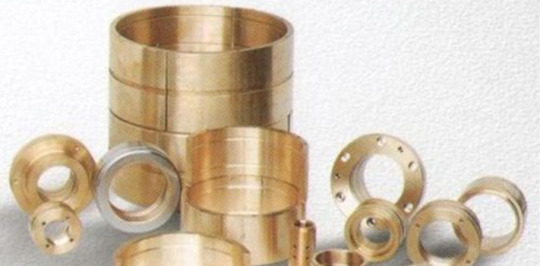
Brass an alloy of copper, as well as zinc, is just one of the most extensively made use of alloys. Understood for its attractive features as well as the brilliant gold look, brass likewise shows sturdiness, deterioration resistance, as well as high electric conductivity.
Brass sheet as well as brass plate are much more flexible than bronze, as well as usually really simple to reduce, making it beneficial in the production, building, electric as well as pipes markets.
Over the centuries, a variety of various procedures have actually been created for making brass, with extra steels, such as lightweight aluminium, lead, as well as arsenic in construction of buildings.
Uses that would surprise you
As a result of its broad adaptability, brass has actually discovered its method right into an unusual variety of applications, consisting of:
> Ammo cases Stimulate immune, low-friction, corrosion-resistant, and non-magnetic, brass can be quickly rolled right into slim sheets as well as created right into cartridge coverings. It is likewise very easy to reuse for ammunition reloading.
> Marine equipment As a result of its solidity, sturdiness, as well as rust resistance also in the visibility of seawater brass was utilised for centuries as sheathing on the hulls of wood marine ships, for navigational devices, as well as later on, aquatic engines as well as pumps.
> Digital circuits For electric panel board buttons as well as relays, in addition to PCB plug pins, outlets and incurable blocks, the flexible, non-magnetic nature of brass, as well as the truth that it sets you back much less than silver and gold, makes it an outstanding selection of product.
> Radiator cores, tubes as well as storage tanks Brazed copper-brass radiators for vehicles set you back much less than lightweight aluminium radiators, are much easier to produce, last much longer, as well as are a lot easier to reuse, that makes them much more power reliable. They have likewise been revealed to have a reduced air-side stress decrease than lightweight aluminium radiators.
These are just some of the functional uses of brass in different industries. But they have a hell lot more usage in the Building and Construction industry. So, it is advisable to check out aluminium and brass manufacturers as well as dealers from a known reputed business directory IBPHub to have you connect easily with the suppliers in your building and construction-related tasks under progress.
Source: https://www.ibphub.com/blog/Local/4-things-you-would-be-surprised-to-know-made-from-brass-22
1 note
·
View note
Text

HLS-13F-4
transparent 14PIN 4C 10A power relay PCB QUICK PIN HLS-13F-4
Dielectric Strength Between Open Contacts:1000VAC 50-60HZ( 1minute)
Dielectric Strength Between Contacts And Coil:1500VAC 50-60HZ (1 minute)
Operate Time:25ms max
Release Time:25ms max
Ambient Temperature:-40 ℃ to+70 ℃
0 notes
Text
6-channel speaker selector
At the beginning of 2018, we developed the first version of the 6-channel speaker selector using PIC16F88 MCU and ULN2803 Darlington transistor array. In this new design, we redesign it with low-cost MCU and Darlington transistor arrays. This design also provides the same functionality as the 6-channel speaker selector switch we designed earlier.
This new speaker selector uses STC15W201 MCU. This MCU is a low-cost 8051 MCU designed by STC micro. At the time of this writing, the STC15W201 can obtain for less than US$ 0.8. To drive the seven segments and to control the relays, this design uses the popular 74HC595 8-bit shift register ICs.

To select each speaker channel, we use pair of 12V DPDT relays. These relays interface to 74HC595 through a ULN2001D 3-channel Darlington transistor array IC. This 3-channel Darlington driver IC is functionally equivalent to the famous 8-channel ULN2003 IC. This ULN2001D version is an 8-pin IC and is available in both DIP-8 and SOP-8 packages.
This new board is designed to work with a 12V DC power supply and in our prototype build, we use a 12V/5A SMPS unit to power the whole system.
To get the optimal results with this circuit, use an Omron G2R-2-12DC or an equivalent type of relay with a coil current lower than 100mA.
The firmware of the STC15W201S is developed using SDCC. To flash the MCU, we use stcgal. Thanks to the built-in bootloader, we can program this MCU using a generally available 5V USB to UART module/dongle.
The complete build process of the speaker selector is shown in the video below:
youtube
The functionality of the firmware is almost identical to the old PIC16F88 firmware. After powering up the system, the active speaker channel is displayed on the seven-segment display. To switch to a different speaker channel, press the button repeatedly with short intervals.
To mute or disconnect the current speaker channel, press and hold the same button for more than 3 seconds.
As described above, all functions of this circuit can be the control using a single push switch.

The PCBWay sponsored this project. PCBWay offers high-quality PCB manufacturing and assembling services. Also, they offer CNC and 3D printing services. The Speaker selector PCB is available to order from PCBWay. Check out the PCBWay website for its manufacturing capabilities and pricing.
This project is an open-source hardware project. All its design files, schematics, and firmware source codes are available at Github.com.
The PCB design, schematic, and other design files of this project are covered with a CERN-OHL-W 2.0 license. Firmware source code is released under the terms of the MIT license.
#audio#8051#STC15W201#ULN2001D#74HC595#switch#speaker-selector#electronic-switch#AMS1117-5.0#PCBWay#prototype#SDCC#Relay#STC#Youtube
0 notes
Text
50 pin molex connector

#50 pin molex connector full
#50 pin molex connector series
Product Pictures Molex 2. Service: Wiring Harness OEM Certificate: CE, RoHS Pin & Socket Connectors PLUG WHITE 94V-0 420 WHITE 94V-0 4202106. Temperature operating temperature, fixed installation: -40☌ to +105☌ Electrical Performance: Rating voltage: 300V AC Rating Current: 3A (22AWG)Ģ.
#50 pin molex connector series
SL Crimp Terminal, Series 70021, Male, ReelĠ.38µm Selective Gold (Au) Plated Contactġ. of 170 watts 50-1037 Transformer/Barrel Jack Male Adapter Cable - Power. SL Crimp Terminal, Series 70021, Male, Reel Packing 6 (+2) pin PCIe connector, a SATA connector, and a Molex connector contents. With its large number of options and configurations, SL Modular Connectors and Assemblies deliver ideal wire-to-wire solutions and its varying PCB termination methods, including reflow process capable versions, support a range of wire-to-board applications.ġ.1 Molex 70400 Series SL 2.54mm pitch wire-to-wire connector housing The Connector housing is male, single row, version A, without mounting ears, 3 circuits, black. China Shenzhen Xaja 50 Pin 30pin to 20 Pin LG LCD Hirose Molex Jst Connector Lvds Cable Type, Find details about China Jst Connector Lvds, Hirose Lvds Cable from Shenzhen Xaja 50 Pin 30pin to 20 Pin LG LCD Hirose Molex Jst Connector Lvds Cable Type - Shenzhen Xi Ang Ju An Electronic Co., Ltd. 50-57-9407 - Molex Heilind Electronics We use cookies to make your experience better. Estimated manufacturer lead time is for quantities greater than shown above. 50-57-9407 - Pin and Socket Housings by Molex at Heilind 1 distributor of connectors, relays, sensors, switches and other electronic components. Molex pins we used were P/N 08-50-0113, and they work with the KK series. 50-84-2150 from Molex Incorporated at Allied Electronics & Automation. Molex SL 70107-0002 3 Pin 2.54mm Pitch Wire-to-Wire Connector Cable AssembliesįLECONN can custom molex sl 70107-0002 2 3 4 5 6 7 8 9 10 11 12 pin 2.54mm pitch wire-to-wire connector cable assemblies. Similarly, you can add Molex connectors to Power Functions wires. 240 V ac at 50/60 Hz Server Power Supply Pinout - Simon Wyss Fortunately.
Waterproof Enclosures/ Housing/ Box Design Buy it with This item: Molex Connector Housing, Plug, 9Pos - 50-84-1090. A qualified PMC IEEE 1386 standard connector that provides a rugged housing and protected pin interface for reliable signal transmission, a slim-body housing that minimizes airflow obstruction and the versatility to be arrayed to increase circuit size. pin MOLEX 39-29-9202 connector and 20 pin MOLEX 39-01-2200 connectorThis.
#50 pin molex connector full
Connectors & Cables Connectors PCB Connectors Pin Headers, Receptacles systems Molex FFC/FPC connector Total number of pins 50 Contact spacing: 0.5 mm 5019515000 2000 pc(s) Tape on Full reel. Jack & DC Plug for IRIS auto camera lens Molex FFC/FPC connector Total number of pins 50 Contact spacing: 0.5 mm 512965094 3000 pc(s) Tape on Full reel. Back to Pin Headers, Receptacles systems.If it is determined during the customer’s evaluation of suitability, that higher performance is required, please contact Molex for possible product options. 6 YRS 4.9 (7) Contact Supplier 1 / 6 Custom auto wire harness 30 40 50 pins with connectors auto electrical pin connector 1.00-8.00/ Piece 1 Piece (Min. The Connector housing is female, single row, version C. Order) CN Dongguan Lanbo Electronics Technology Co., Ltd. FLECONN can assemble molex 2.54mm pitch 70066 series 50-57-9212 sl 12 pin connector wire harness. The customers using this product must determine its suitability for use in their particular application through testing or other acceptable means as described in end-product glow-wire flammability test standard IEC 6 and any applicable product end-use standard(s). 50 Pin Right Angle Male Shrouded PCB IDC Socket Box header Electrical Connector for Cars 0.06-0.30/ Piece 1000 Pieces (Min. This Molex product is manufactured from material that has the following ratings, tested by independent agencies :Ī) A Glow Wire Ignition Temperature (GWIT) of at least 775 deg C per IEC 6.ī) A Glow Wire Flammability Index (GWFI) above 850 deg C per IEC 6.and hence complies with the requirements set out in the International Standard IEC 60335-1 5th edition - household and similar electrical appliances - safety section 30 Resistance to heat and fire.
0 notes
Text
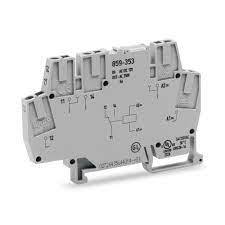
Channel Relay Module: Everything you need to know
The 4 Channel Relay Module controls high-voltage, high-current load such as motor, solenoid valves, power lamps, and AC load. The 4 Channel Relay Module comprises four 5V relays and the associated switching and isolating components, making the interfacing with a microcontroller or sensor easy with minimum features and connections.
Relay modules can be used across industries, including process technology and power engineering, railway applications, machine engineering, and general control cabinet construction.
Technical Data
• Number of digital outputs: 4 • Total number of channels (module): 4 • Actuator connection: 4 x (1-wire) • Output circuit design: 4 make contacts Relay • Output characteristic: potential-free • Switching frequency (max.): 0.33 Hz; 3 A / 250 VAC, 30 VDC • Switching frequency (max.) (2): 0.1 Hz; 5 A / 250 VAC, 30 VDC • Load type of switching frequency: 3 A / 250 VAC, 30 VDC • Switching voltage (max.): 250 VAC; 30 VDC; 110 VDC at 0.4 A • Switching current (max.): 2A • Switching current (note): 5 A for single-channel use • Switching power: 1250 VA / 150 W; cos ϕ max. = 0.4; L/R max. = 7 ms • Pull-in time (max.): 10ms • Drop-out time (max.): 5ms • Bounce time (typ.): 1ms • Electrical switching operations (min.) (at max. resistive load): 100 x 10³ switching operations • Mechanical switching operations (min.) (at max. resistive load): 20 x 10⁶ switching operations • Output data width (internal) max.: 4bits • Supply voltage (system): 5 VDC; via data contacts • Current consumption (5 V system supply) 95mA • Isolation: 1500 V (system/field) • Indicators: LED (A-D) green: Status relay 1 … relay 4
Features
• Input supply 12 VDC @ 170 mA • Output four SPDT relay • Relay specification 5 A @ 230 VAC • Trigger level 2 ~ 5 VDC • Berg pins for connecting power and triggering voltage • LED on each channel indicates relay status • Power Battery Terminal (PBT) for accessible relay output and aux power connection • Four mounting holes of 3.2 mm each • PCB dimensions 88 mm x 68 mm
Four-Channel Relay Module Usage
The most significant advantage of the 4 Channel Relay Module is that it can switch multiple loads at the same time due to four relays present on the same module. This type of relay module provides the perfect solution for home automation. It can be placed in the main switchboard, connected to loads in other parts of the house, and controlled from a central location using a microcontroller.
Benefits of Relay Modules
• Electromagnetic relays have a fast process and speedy reset • They can be operated for both AC and DC systems for the safety of AC and DC equipment • Electromagnetic relays operate at speeds that can manage in milliseconds and are also possible • Relay Modules are simple, robust, compact, and reliable • These relays are almost instantaneous. Though quick, the operating time of the relay varies with the current. With different setups like dashpot, copper rings, etc., slow operational duration and reset can be possible.
How does it work?
This relay module has three high voltage terminals (Normally Closed (NC), Common terminal (C), and Normally Open (NO)) that attach to the device you want to handle. The other side has three low voltage pins (Ground, Vcc, and Signal) that join Arduino.
0 notes
Text
Boss Muff
I love Boss pedals, they are bomb proof, have a great form factor, work well, and look great. They don’t make a couple effects that I like. For example you can’t get a Big Muff in Boss. I had the idea to rehouse some effects in Boss enclosures. Here is the Boss Muff.
The Boss Muff is a Green Russian Big Muff in DS-1 enclosure
Sourcing enclosures
I couldn’t find empty Boss enclosures for sale anywhere so I had to recycle. Boss pedals keep a good resale. It’s hard to find these for less than $40. Often used Boss pedals go for $100 or more. I didn’t want to pay $40 for an enclosure but I wasn’t going to pay $100, especially for something I might want to keep.
After some research on Reverb I found the Boss DS-1 was cheapest. Typically they go for ~$40. The historical prices show sales a range of $25 to $45. Reverb says the estimated price is $25 to $35.
Check out historical sales on Reverb here: Boss DS-1 Distortion (Silver Label) 1994 – 2021
Note! New Boss DS-1 and Boss SD-1 go for about $50. If you have a discount or see a sale it might be good to buy a new pedal since places like Sweetwater offer free shipping.
Watch the shipping! People will ask $15 on average which is really high for something where the asking price is $40. Typically I can mail a pedal for $6 to $10 USPS.
This is the donor DS-1 for ~$40 from Reverb.
The enclosure and parts
The enclosure is great, it’s pretty spacious, pre-drilled, and it comes with some usable parts. It’s even partially pre-wired!
It comes with jacks, LED, battery clip, a momentary SPST switch, knobs, and some pots. It also comes with a DC power jack but, this was mounted to the original PCB, there will be nothing to anchor it to when I replace the board so I couldn’t use it.
The contents of the DS-1 and the replacement boards.
The Jacks are useable and the wiring can be repurposed. There’s nothing special about these jacks. It is interesting the way they fit the enclosure. You don’t need hold them from the inside when you tighten the nut.
The LED is mounted to a small board. I used the LED and board. I just replaced the wires because I needed a little more length. The LED is a typical red 3mm type. Nothing special here.
I usually don’t use a battery but, since the clip was there and partially wired it was easier to just keep it! I wired up the battery snap for this build.
I went with a relay switching system, more on this below, the existing switch worked well for this! I left the existing switch in place along with the wires.
The pots from the DS-1 were B100k, B100k, and B20k. Since I was building a Big Muff I needed 3 x 100k pots. I kept two of the original pots and replaced the 20k pot with a A100k pot. The two B100k pots were 16mm and B20k was a 9mm pot with pins at 90 degrees. It looks like you could fit 3 x 16mm pots but I didn’t test this theory and just brought another 9mm pot.
Pots from the original DS-1 mounted to the new PCB with the original ribbon cable.
All of the pots had a small PCB with a ribbon cable running to the main PCB. I used these small boards and the existing ribbon cables.
Note! The ribbon cables use thin solid core wires. These seem like they would break easily but Boss glues both ends to their respective boards with some kind of industrial glue, maybe epoxy. I took their lead and glued the end of the ribbon cable to the PCB with some gorilla glue. The glue anchors the end of the wire where it’s prone to breaking.
Small PCBs mounted to pots
Ribbon cables glued to PCB
They did the same with the DC jack, this type of jack is prone separating from the board on other pedals, I’ve fixed a few of these in the past. Not on Boss pedal! The jack is soldered then glued to the board! I’m surprised other manufacturers haven’t caught on to this.
I reamed the enclosure to fit a standard DC jack. I used a couple of those plastic washer to keep the jack from extending too far out of the enclosure.
Add some washers
Ream the enclosure
Mounting the DC jack
Adding the DC Power jack to the Boss enclosure
The knobs are nothing special. They use splined knobs rather than knobs with a set screw. I kept the pots so I kept the knobs. I had to get a new knob for the replaced 9mm pot since I couldn’t get a 9mm pot with a splined shaft or at least a 9mm pot with 90 degree pins with a splined shaft.
Switching
Boss uses an electronic switching system paired with a buffered bypass. Seems like you could use this some how. This might be a future project…
For this project I decided on something I could more easily understand. I went with a relay switching system. This is an electronic DPDT that includes a circuit that also handles the LED. The system uses a Microcontroller that tracks the SPST, powers the LED and switches the relay.
Madbean Softie (left) and Rabbithole (right) PCBs
I went with the Madbean pedals Softie system. It has some good features. It is also true bypass. The effect path through the relay is essentially a wire connection all the way through. A nice feature of the Softie is if the power goes off it switches to bypass. The relay has an estimated failure of 100k clicks so it should outlast a stomp switch.
I chose the Softie 2 board. Madbean offers three PCB versions 1, 2, and 3. The Softie 2 is made for 1590B sized boxes. I thought this would good but I wasn’t thinking in 3D. This board mounts parts on both sides which makes it taller even though the footprint is smaller than the other boards. I still made it work but, a wider flatter board, with all the parts on one side, would work better in this enclosure.
Softie PCB and relay
Softie PCB
The Softie works well. Assembly is easy. Some of the parts you’ll need to order from Mouser so it won’t be as cheap as a 3PDT switch. Wiring is easy. Overall I’d recommend this for other projects.
Cost estimate
ItemCost Used Boss DS-1$40 Madbean Rabbit Hole PCB$6 Madbean Softie PCB$4 Relay 80-EC2-4.5NU$2 Other parts$5 total estimate$57
Cost estimate to build a Big Muff in a Boss enclosure
But What about the finish?
I didn’t paint the enclosure. This would have added a lot of time, cost, and effort to the project. Admittedly it would have looked far more amazing when it was finally finished. I was not super excited to try and peel off that rubber pad on the foot switch and glue it back on. You might be able to mask this. Also sanding the enclosure did not inspire me.
I think I might just slap a label on this to remind me what’s in the box. As it is the existing labels: Tone, Level, and Dist work for the Big Muff. Though the arrangement is not what I would have done. The small center knob is Level. Intuitively I reach for the upper left when I want to adjust the Volume. Sounds!
Here is a short video clip of a stock Boss DS-1 next to the Boss Muff. I built the Boss Muff to the spec of a Green Russian Big Muff. Not sure if I made a mistake or if it’s the nature of the green Russian but it has lots of bass. This would be great for bass.
youtube
Conclusion
So was it worth it? The whole process was easier than I thought it would be. The cost was higher than building other projects but not as high as I thought it might be. Reusing parts from the DS-1 saved on costs for pots, jacks and knobs which are some of the more expensive parts.
I could have shaved the costs down if I could have traded for a Boss pedal or watched Reverb for a couple weeks looking for a deal. I just bought the cheapest DS-1 I saw and paid the asking price. Besides waiting for a $25 DS-1 to show up on Reverb and then see $15 shipping is a little anticlimactic.
Overall the experience was informative. I think I enjoy having the rehoused Big Muff. I’ll probably use this pedal. The process revealed some of the tech used by Boss in their pedals. I’m definitely going to do a follow up…
Check out this Make Guitar Podcast where we talk about building the Boss Muff:
youtube
Boss Muff was originally published on Super-Freq
1 note
·
View note
Photo

The L293D motor driver is available for providing users with ease and user-friendly interfacing for embedded applications. L293D motor driver is mounted on a good quality, single sided non-PTH PCB. The pins of L293D motor driver IC are connected to connectors for easy access to the driver IC’s pin functions. The L293D is a Dual Full Bridge driver that can drive up to 1Amp per bridge with a supply voltage of up to 24V. It can drive two DC motors, relays, solenoids, etc. The device is TTL compatible. Two H bridges of L293D can be connected in parallel to increase its current capacity to 2 Amp.
https://www.campuscomponent.com/products/l293d-motor-driver-board/2208614000001862485
0 notes
Text
Classification of digital elements
Resistors: plug-in film (colour ring) resistors, steel film resistors, metal oxide film resistors, carbon film resistors, cord wound resistors, cement resistors, aluminium instance resistors, ceramic chip resistors, thermistors, pressure-sensitive resistors, and so on.
Capacitors: aluminium electrolytic capacitors, tantalum capacitor factor capacitors, polyester capacitors, polypropylene film capacitors, metalized polypropylene film capacitors, ceramic capacitors, security capacitors, anti-EMI capacitors, etc.
Potentiometers: wire-wound potentiometers, conductive plastic potentiometers, metal-ceramic potentiometers, carbon movie potentiometers, trimmer potentiometers, panel potentiometers, accuracy potentiometers, straight-slide potentiometers, and so on.
Magnetic elements: wire-wound chip inductors, laminated chip inductors, axial inductors, colour-coded inductors, radial inductors, toroidal inductors, chip grains, plug-in beads, commercial regularity transformers, audio transformers, switching power transformers, pulse signal transformers, RF transformers, etc.
Buttons: slide switch, change button, light touch switch, mini switch, button switch, essential button, straight vital switch, rotating button, dip switch, membrane layer switch, and so on.
Relays: DC electro-magnetic relays, A/C, magnetic retention relays, reed relays, solid-state relays, etc.
Connectors: the row of pins and row of ladies, European adapters, bullhorn ports, easy bull connectors, IDC ports, XH adapters, VH linkers, D-SUB adapters, crystal head crystal holders, power adapters, plug jacks, IC owners, RF linkers, fibre optic wire adapters, European terminals, fencing terminals, plug-in terminals, rail terminals, spring terminals, earphones Socket plugs, round bare terminals, and so on.
Insurance parts: fuse, fuse, gas discharge tube, etc.
Filter components: piezoelectric ceramic filters, SAW oscillators, quartz crystal filters.
PCB board: paper-based PCB, glass cloth-based PCB, artificial fiber PCB, ceramic-based PCB, etc.
Motor fan: DC motor, a/c motor, AC generator, DC generator, AC follower, DC follower, and so on.
Electro-acoustic devices: speakers, microphones, receivers, transmitters, transmitter-receiver mixes, earphones, pickups, buzzers, buzzers, and so on.
Cables: enamelled cable, cord and also wire, fiber optic cable, etc.
Diodes: rectifier diodes, fast recuperation diodes, ultra-fast healing diodes, Schottky diodes, switching diodes, voltage regulatory authority diodes, transient suppression diodes, TVS diodes, varactor diodes, trigger diodes, light-emitting diodes, and so on.
Triode: PNP type triode, NPN type triode. General-purpose tiny power transistors, switching over transistors, general-purpose power transistors, Darlington tubes, low-saturation transistors, voltage drop transistors, electronic transistors, with resistance transistors, RF transistors, etc.
Integrated circuit ICs: Analog ICs Power administration ICs: linear voltage regulator ICs, voltage referral ICs, switching voltage regulatory authority controllers, functional amplifiers, voltage comparators.
Digital ICs, basic reasoning ICs: buffers, drivers, flip-flops, latches, signs up, gates, encoders, decoders, counters, transceivers, and degree converters.
Processor: CPU, Microcontroller, DSP, FPGA, CPLD.
Storage: DRAM, SRAM, PROM, EPROM, EEPROM, FLASH MEMORY.
Other classifications: user interface IC, clock IC, ADC converter, DAC to the tool, unique IC custom-made IC, microblogging IC, hybrid IC, and so on.
Crystal oscillator: average crystal oscillator, temperature complementary crystal oscillator, consistent temperature level crystal oscillator, voltage control crystal oscillator, and so on.
Display devices: digital tubes, LED gadgets, OLED display screens, LCD liquid crystal screens, and so on.
Sensing units: Hall sensing units, temperature sensing units, etc.
0 notes
Text
Electronic Spices Stabilizer 3,5 Step Universal PCB BOARD 3 STEP LOW CUT With all
Electronic Spices Stabilizer 3,5 Step Universal PCB BOARD 3 STEP LOW CUT With all
Price: (as of – Details) Microcontroller based technology. Easily adjustable with any specified and capacity transformer upto 20 KV. Relay operated with zero crossing for getting low sparking and highly durability. Instant start and low cut off onfigurable pin available on PCB. Single preset ajustable with all step functionaliyt. Highly voltage accurate 10 bits ADC. Combo power supply, zener and…

View On WordPress
0 notes
Text

HLS6-4100H
SPDT 6PIN 3A telecom relay PCB PIN HLS6-4100H
0 notes
Text
Obtain The Single Sided PCB Machine at Shree Ram Electronics
As India is moving towards a democratic country so many industries in India nowadays are preferring to manufacture their own appliances rather than preferring any foreign brands. They are using their own raw materials and manufacturing by their own manpower. Moreover, as our pm has taken the initiative of the Make in India concept so this has added additional progress in the above mention field. Keeping this the first priority we at Shree Ram Electronics we are the manufacturer as well as the distributor of different types of PCB machines. Those are the single-sided and the double-sided ones. The double-sided PCBs are complex ones as compared to the single-sided ones but both devices are best in their own ways. In the past, these machines were made in convenient methodology but now it is being manufactured by the latest technology and invention. There are various single sided pcb manufacturer in india but Shree Ram Electronics is the perfect one.
This company is dedicated to manufacturing high-quality, innovative, and cost-effective end-to-end electronics appliances to valuable customers. Our main objective is to satisfy our customers irrespective of their demands so we make things precise and convenient. We are expertise in PCB with a minimum hole diameter of 0.025mm, less track width 0.304mm, More Board Thickness 0.2mm to 3.2mm, Copper Plating Thickness-18u,35u,70u, less SMD Pin Width 0.25mm. We are also serving our customers multilayer PCB, metal PCB, and flexible pcbs. We always keep the following mention factor as our first priority like the customer vision is our goal, we serve products as per the customer satisfaction, manufacture more number of products within less time of span, deliver high-quality products, the quality is the best in the market. Once any customer will visit our store and purchase the products then he will never even think about the second option as we are the organization that never lags behind any point when it comes to customer satisfaction.
The Single-sided PCB is a admired circuit board that comprises of a single conductive copper layer above the substrate. The electrical components are organized onto one side of the board and the whole circuit can be seen through the other side.
These circuits are measured as one of the best options for a wide range of applications due to the numerous advantages it serves. As the design is very simple so it is less expensive and affordable because of the simple design. The boards are very simple to design so it helps the manufacturer to build a number of PCB at very little time of span, as a result of which these circuits are being used in very various appliances and electronics circuits.
The simplicity of these devices is the most crucial factor that makes them different from the rest devices. Not only these are used in simple applications they are applicable for various complex applications like Power supplies, Relays Timing circuits, Sensor products, LED lighting, Radio and stereo equipment, Packaging appliance, Printing devices, Coffee machines, Vending machinery, Solid-state devices, and Camera systems many more. If you are wondering from which single sided pcb manufacturer in india to trust? Then you are at the right place. Now explore the PCBs by visiting our official website at www.shreeramelectronics.com.
1 note
·
View note