#Relay switch circuit
Explore tagged Tumblr posts
Text
https://www.futureelectronics.com/p/electromechanical--relays--power-relays/3-1415055-1-te-connectivity-7479868
What is a Power Relay, Power relay module, Transistor relay switch
SR4 D/M Series 24 V 8 A PC Pin PCB Mount Force Guided Contact Relay
#Relays#Power Relays#3-1415055-1#TE Connectivity#P module#Transistor relay switch#reverse power relays#power relay assembly#Power relay circuit#relay socket#power relay switch#High power relay switch#Relay switch circuit
1 note
·
View note
Text
Relay Switch Circuit, NPN Relay Switch Circuit
2-1415898-3 RT1 Series 12 V 16 A 360 Ohm PCB Mount Inrush Power Relay
#TE Connectivity#2-1415898-3#Relays#Power Relays#Relay Switch Circuit#NPN Relay Switch Circuit#Common Emitter Darlington relay#PNP Collector Configuration#Automotive Relays#Reed Relays#High Power Relay#signal relays
1 note
·
View note
Text
https://www.futureelectronics.com/p/electromechanical--relays--solid-state-relays/cpc1017ntr-littelfuse-3938842
Power switch, SSR solid state, Quick connect auto, SPST, non latching, DIP,
CPC1017N Series 100 mA 60 V SPST Surface Mount OptoMOS® Relay - SOIC-4
#Relays#Solid State Relays (SSRs)#CPC1017NTR#Littelfuse#Power switch#Quick connect auto#SPST#non latching#DIP#Solar Inverter Relays#High voltage#Reed relay circuit#aromat#Electromechanical relay#Clare#Integrated Circuits Division
5 notes
·
View notes
Text
youtube
Old pinball machines are amazingly complex
#technology connections#pinball#electromechanical systems#solenoids#relays#switches#complete the circuit
2 notes
·
View notes
Text
Transistor relay switch circuit, High voltage relays, reverse power relays
CPC1025N Series SPST-NO 120 mA 400 V SMT Solid State Relay - SOIC-4
0 notes
Text
https://www.futureelectronics.com/p/electromechanical--relays--power-relays/3-1461491-6-te-connectivity-5315767
Power relay switch circuit, Power relay socket, Panasonic Electric Works
PCN Series 3 A SPST (1 Form A) 24 VDC PCB Mount Slim General Purpose Power Relay
#Relays#Power Relays#3-1461491-6#TE Connectivity#switch circuit#Power relay socket#Panasonic Electric Works#4 pin relay wiring diagram#SPDT#SPST#latching power relays#24VDC Power relay#12VDC power relays#Power relays by Potter
1 note
·
View note
Text

Quality You Can Trust: Elevate Your Projects with Our Electromechanical Parts!
Electromechanicals for Sale are premier supplier of electromechanical components and industrial automation spare parts. Explore our extensive catalog of electromechanical parts and components. As the premier supplier, we offer industrial automation spare parts and components for all your needs such as Servo Motors Active, Passive, & Sensor Parts, Power Supplies, Circuit Protection, Industrial Automation, Switches Automation, Control Gear, Electronic Connectors Relays and more. We supply electromechanical parts for leading manufacturers of Industrial automation.
Here at Electromechanicals for sale, quality is of the utmost importance. All parts found on our website trace back to leading automation spare parts suppliers and manufacturers that we trust, and countless listings undergo varying levels of testing, inspection, and document verification prior to shipment.
#Electromechanical Parts#Industrial Automation#Electronic components#Electronic industry#Industrial Lighting#Marine Electronics#Electronics Component Connectors#Electrical Switches & Relay#Circuit Board Accessories
1 note
·
View note
Text
https://www.futureelectronics.com/p/semiconductors--optoelectronics--isolation-components-optocouplers/ps2501l-1-f3-a-renesas-1397785
Optocoupler as a switch, opto-isolator Optocoupler relay, optocoupler ic
PS2501 Series Single Channel 80 Vce 5000 Vrms SMT Photocoupler - DIP-4
#Renesas#PS2501L-1-F3-A#Optoelectronics#Isolation Components#Optocouplers#switch#opto-isolator Optocoupler relay#Phototransistor#High speed optocoupler#Optocoupler circuit#isolated circuits#opto coupler
0 notes
Text
https://www.futureelectronics.com/p/electromechanical--relays--power-relays/1415898-6-te-connectivity-2059108
What Is a Power Relay, latching power relays, power relay switch circuit
RT1 Series SPST (1 Form A) 16 A 12 V PCB Mount General Purpose Power Relay
#Relays#Power Relays#1415898-6#TE Connectivity#module#power relay de-energized#power relay switch#latching power relays#power relay switch circuit#Power relay socket#Power windows#switch on/off#power relay control circuit
1 note
·
View note
Text
Optocoupler relay, isolated circuit, Optocoupler circuit, High voltage optocoupler
DIP6 SMT 1 Channel 400 V 4170 Vrms Zero-Cross Triac Optoisolator
#Optoelectronics#Isolation Components#Optocouplers#MOC3043SR2M#Onsemi#opto-isolator module#Triac opto isolator#Phototransistor Optocoupler#High speed#switch#Optocoupler relay module#isolated circuit#circuit#High voltage
1 note
·
View note
Text
Understanding Relay Module Circuits: A Comprehensive Guide
Introduction:
Relay module circuits are essential components in various electronic and electrical applications. These circuits act as switches, allowing control signals from one circuit to activate or deactivate another circuit. Relay modules provide an efficient way to isolate high-power devices from low-power control systems, ensuring safety and protection. In this comprehensive guide, we will delve into the fundamentals of relay module circuits, their working principles, applications, and address some frequently asked questions (FAQs) to provide a complete understanding of this crucial aspect of modern electronics.
I. What is a Relay Module Circuit?
A relay module circuit consists of an electromechanical relay mounted on a PCB (Printed Circuit Board). The relay is an electromagnetic switch that is actuated by a control signal, which can be either digital or analog. When the control signal triggers the relay, it closes or opens the electrical contacts, allowing current to flow through the output terminals and control external devices or circuits.
II. How Does a Relay Module Circuit Work?
Electromagnetic Coil: The relay module circuit has an electromagnetic coil that serves as the input or control element. When an appropriate voltage is applied to the coil, it creates a magnetic field, causing the relay's armature to move.
Normally Open (NO) and Normally Closed (NC) Contacts: A relay typically has two sets of contacts: Normally Open (NO) and Normally Closed (NC). In the resting state, the NO contacts remain open, and the NC contacts remain closed.
Switching Action: When the coil is energized, the armature moves, causing the NO contacts to close and the NC contacts to open. This switching action completes or interrupts the circuit, depending on the application.
III. Types of Relay Module Circuits:
Single-Pole, Single-Throw (SPST) Relay: SPST relays have one set of contacts and can either be Normally Open or Normally Closed.
Single-Pole, Double-Throw (SPDT) Relay: SPDT relays have one set of normally open contacts and one set of normally closed contacts. When the relay is energized, the NO contacts close, and the NC contacts open.
Double-Pole, Single-Throw (DPST) Relay: DPST relays have two sets of contacts that operate simultaneously, making or breaking the circuit.
Double-Pole, Double-Throw (DPDT) Relay: DPDT relays have two sets of NO contacts and two sets of NC contacts. They provide two separate circuits that can be independently controlled.
IV. Applications of Relay Module Circuits:
Home Automation: Relay modules are commonly used in home automation systems to control lighting, heating, ventilation, and air conditioning (HVAC) systems.
Industrial Automation: In industrial automation, relay modules are used to control motors, pumps, solenoids, and other high-power devices.
Automotive Electronics: In automobiles, relay modules are utilized to control various electrical systems, such as headlights, windshield wipers, and electric windows.
Robotics: Relay module circuits are used in robotics to control the movement of actuators and motors.
Security Systems: In security systems, relay modules are used to trigger alarms and control access points.
V. Advantages of Using Relay Module Circuits:
Isolation: Relay module circuits provide galvanic isolation between the control circuit and the load, ensuring safety and protecting sensitive components.
Low Power Control: Relay modules allow low-power control systems to switch high-power devices, eliminating the need for high-power control circuits.
Versatility: Relay module circuits are available in various configurations and voltage ratings, making them versatile and suitable for a wide range of applications.
Simple Operation: Relay modules are easy to install and operate, making them a popular choice in many electronic applications.
FAQs:
Q1. Can relay module circuits be used for both AC and DC applications? Yes, relay modules are available in both AC and DC versions, allowing them to be used in a wide range of applications.
Q2. What is the difference between a relay and a relay module? A relay is the basic electromagnetic switch, while a relay module includes the relay mounted on a PCB with additional circuitry for ease of use and integration into other systems.
Q3. Can relay modules handle high-current applications? Yes, relay modules are available in different current ratings, and they can handle high-current applications as per their specifications.
Q4. How do I choose the right relay module for my application? When selecting a relay module, consider the voltage and current requirements of your application, the type of load (AC or DC), and the number of contacts needed.
Q5. Can I use a relay module to control multiple devices simultaneously? Yes, some relay modules have multiple sets of contacts (DPDT or more), allowing you to control multiple devices independently.
Conclusion:
Relay module circuits are versatile and indispensable components in modern electronics and electrical systems. Their ability to provide isolation, low-power control, and versatility makes them ideal for a wide range of applications in various industries. By understanding the working principles and different types of relay modules, along with their numerous applications, designers and engineers can make informed decisions when integrating these circuits into their projects. Relay module circuits continue to play a critical role in enhancing the efficiency and control capabilities of electronic systems, contributing to advancements in automation and smart technologies.
0 notes
Text
High-speed switching, Power relays, Solid State Relays (SSRs)
1415898-6 24 Vdc 650 mW 250 Vac 16 A Power PCB Relay
#Relays#Power Relays#1415898-6#TE Connectivity#High-speed switching#Power relays#Solid State Relays (SSRs)#types of relays#transistor relay switch circuit#reverse power relays#digital relays#low power relays#low voltage relay switch circuit
1 note
·
View note
Text
https://www.futureelectronics.com/p/semiconductors--optoelectronics--isolation-components-optocouplers/ps2501l-1-f3-a-renesas-1397785
Optocoupler as a switch, opto-isolator Optocoupler relay, optocoupler ic
PS2501 Series Single Channel 80 Vce 5000 Vrms SMT Photocoupler - DIP-4
#Renesas#PS2501L-1-F3-A#Optoelectronics#Isolation Components#Optocouplers#switch#opto-isolator Optocoupler relay#Phototransistor#High speed optocoupler#Optocoupler circuit#isolated circuits#opto coupler
1 note
·
View note
Text
Mosfet gate, mosfet model, power Mosfets, mosfet switch, mosfet module
1415898 RT1 Series SPST (1 Form A) 16 A 12 V PCB Mount General Purpose Power Relay
#TE Connectivity#1415898#Relays#Power Relays#Mosfet gate#mosfet model#power Mosfets#mosfet switch#mosfet module#Mosfet switch#high current mosfet#High current mosfet#mosfet explained#Mosfet transistor#Mosfet circuits
1 note
·
View note
Text


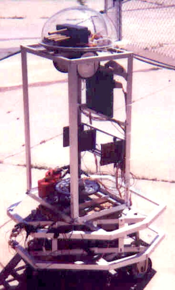
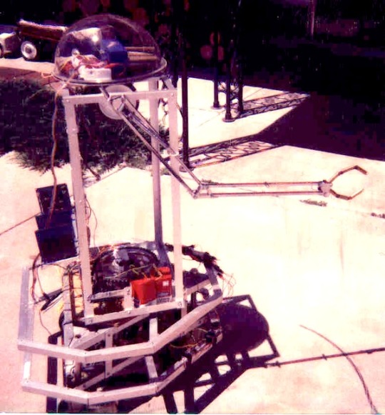
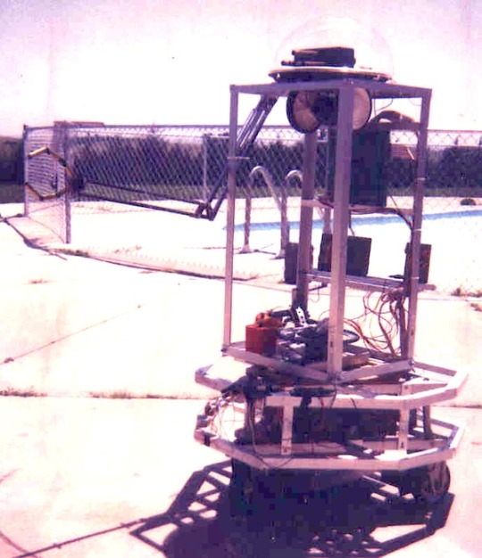
S.A.M by "Bill" (1978). "S.A.M (Short for "Sentient, Autonomous Mechanism" or "Smart Ass Machine", depending on his (and my) mood on a given day, was one of my first real robot projects, started in 1978 when I was around 15. His "brain" was a single-board Z-80 computer (the big square object in the middle of his "back" in this picture), with many bits of TTL I/O, a couple of serial ports, a bunch of counter-timers, and several D/A & A/D channels. The base was taken from the book "How to Build a Computer Controlled Robot" by Todd Loofbourrow - I had built the robot in the book, and had used my KIM-1 to control it. Later, I decided that just a little platform was kind of boring, so I added the upper torso shown here. The torso (mounted on a "lazy-susan" turntable bearing) is rotated by a heavy-duty gear motor driving a chain and sprocket assembly from a bicycle. The base is powered by two of the (apparently no longer available, which is sad) all-metal rubber-tired "motorized wheel" assemblies that Herbach & Rademan used to sell, with a large rubber-tired caster in front. The head platform (mounted on a small "lazy-susan" bearing) was originally rotated by a surplus gearbox from a Mattel "Big Trak" with some rubber-tired wheels mounted on the output shafts. This arrangement was later replaced by a small gear-head motor driving a large gear mounted to the center of the turntable. The device in the head with the tubes sticking out the front is a directional light tracking device. Each tube has a CDS photocell at the bottom, and is painted flat black inside. A comparator circuit tells the computer which direction the brightest light is coming from. This device could also tilt up and down with a small gear-head motor, to track light sources vertically. Most of the circuitry was installed on small plug-boards from Radio Shack, mounted in a card rack below the CPU card. This rack could be tipped back 90 degrees to facilitate easier access for testing. In addition to motor driver circuits, there was a "Sweet Talker" speech synthesizer board so he could talk. Power came from a large "gel-cell" marine battery (for powering trolling motors on boats), which was slung near the ground in the center of the base. Two 6V lantern batteries (later replaced by a 12V motorcycle battery) provided separate power for the electronics. All motors were isolated from the electronics via relays and/or opto-isolators. After these pictures were taken, a set of metal panels was installed on the "facets" of the base, with lever switches behind them for collision sensing. A Polaroid sonar range-finder was also added later. If you check out the other photos of S.A.M., you will notice an "arm" sticking out the front. This was a prototype made from an old swing-arm desk lamp and some "fingers" from a robot hand design using brass tubing, bicycle chain, and 1/16" steel cable to allow natural bending of each finger. It was later replaced with a much heavier duty aluminum framework arm operated by two 12VDC linear actuators." – My Home Robot Projects, by Bill.
25 notes
·
View notes
Text

On this day:
UFO SUCKS POWER OUT
On August 17, 1959, in Brazil, the automatic breakers at Minas Gerais electric power plant unexplainably switched themselves open, cutting off current flowing to the trunk lines. Technicians checked the system and found nothing amiss. An employee from one of the substations called and was warned about drinking on the job when he reported that a UFO flying so low overhead had caused the keys to automatically disconnect, breaking the circuit and stopping the electricity from flowing. The chief engineer at the main station began to turn the breakers back on, but when he flipped the final switch, they all popped open again. From outside, cries of alarm were heard, and the chief ran out in time to witness a spectacular flying saucer coming up the path of power lines from the disabled substation that had called in. Once the UFO had left the area, the power was restored with no ill effects.
In 1963, Denver, Colorado was the victim of an abrupt power outage when the electricity was mysteriously blocked, disabling relay lines due to an overload of power to further cities. Nearly an hour and a half later the current began to flow again. Equipment was thoroughly checked for malfunctions but nothing could be found.
Electrical interference is often reported in connection with UFO sightings. Hundreds of cases from around the world have been documented. Once the alien craft has left the area, operations usually return to normal.
Text from: Almanac of the Infamous, the Incredible, and the Ignored by Juanita Rose Violins, published by Weiser Books, 2009
19 notes
·
View notes