#NPN Relay Switch Circuit
Explore tagged Tumblr posts
Visit Tumblr Blog
Explore Tumblr blogs with no restrictions, modern design and the best experience.
Last Seen Tumblr Blogs


Fun Fact
Total funding amounts to $125.3M.
Text
Relay Switch Circuit, NPN Relay Switch Circuit
2-1415898-3 RT1 Series 12 V 16 A 360 Ohm PCB Mount Inrush Power Relay
#TE Connectivity#2-1415898-3#Relays#Power Relays#Relay Switch Circuit#NPN Relay Switch Circuit#Common Emitter Darlington relay#PNP Collector Configuration#Automotive Relays#Reed Relays#High Power Relay#signal relays
1 note
·
View note
Text
Factory of FUZZ (fuzz factory clone)
I’m always looking for the cheapest way to build pedals. I found these boards on OSH Park.com. Besides being a service for prototyping boards it’s also an open source repository of projects uploaded by the community. A board uploaded to OSH Park marked public can be ordered by anyone. The search function is not so great but it is searchable. I spent a day searching OSH Park for stompbox projects and found more than a few things that look worth building.
The OSH Park standard service is $5 per square inch with the requirement that you order three boards, and shipping is free. This usually cheaper than ordering boards from vendors but there is no support. One of the projects I found was a this Fuzz Factory. It looked well laid out and the cost was $7.75 for 3 boards, about $2.50 per board, which was pretty reasonable.
Order some of these boards here: https://oshpark.com/shared_projects/xaBILSTV. Check out my projects page for links to some OSH Park boards I designed. I have documentation here on my site.
With no build Docs you’re on your own. The Fuzz Factory is not a complex pedal and the schematic is readily available. Some OSH Park projects will link to documentation and other do not. This is a good way to level up your skills!
Getting Started
The Fuzz Factory is not a hard pedal to clone. The toughest part is wiring the pots. Getting a board where the pots mount directly to the board is a great help. Here three of the five pots mount to the board and two require off board wiring which makes a pretty easy build.
The Fuzz Factory has only a handful of parts. I soldered everything except the pots and the two germanium transistors. You’ll want to test a few transistors if you’re using germanium to get some that sound best. That said really everything even silicon can sound good in this circuit.
The Enclosure
For the enclosure I used a black powder coat 1590B from Tayda. For the logo and labels I milled the box using a desktop mill. The powder coat is removed to reveal the design. I created the design in Sketch on the computer exported some SVG files and loaded these into the mill.
Switching
I decided to try out a relay switching system. This uses a soft touch momentary SPST switch and some circuitry. I used boards from DIYGuitarPedals.com. Their system uses some discreet logic and a relay to handle switching and the status LED.
The PCB is designed to fit a 1590B or larger enclosure. It requires a few parts which are mostly easily available. The relay is available through Mouser. Erik over at DIYGuitarPedals was generous enough to send me two boards and the relays, thanks again Erik! Check out their web site and their YouTube channel.
The system uses a relay which is an electromechanical switch in a little box. The switch in this case is the RY9W-K. It’s a DPDT but rather than being engaged by a button or lever it’s engaging by an electrical voltage applied to a control pin.
In the picture below you can see the relay has 8 pins. The 6 pins on the left are the switching connections, each row is one switch, the center is the common connection that bridge to the outer connections depending on the state of the switch. Hey those six pins on the left are just like the pins on a regular DPDT switch-. The two pins on the right are the control and ground.
The board, relay, SPST switch, and other parts make up a single assembly that replace the 3PDT switches typically used for guitar pedals. You can see it neatly fits the lower bout of the 1590B enclosure.
Here is what the whole system looks like assembled. This is complete and could be dropped into any pedal replacing the standard blue 3PDT.
How does it work?
Unlike many relay systems that rely on a micro controllers this circuit uses only discreet logic. There are pros and cons to each. Using a micro controller requires some extra circuitry since the Micro Controller runs on 5v. They can be proprietary since someone has to write the software that runs the system. Using a Micro controller you can fit all the logic into an 8 pin DIP and add new features or up date the existing code. Using discreet logic your system can run on 9v, might have fewer parts, and won’t suffer from software bugs.
This system relies on the 4011 quad NAND gate to handle the switching logic. Check out this video for a more in-depth explanation of the switching logic.
youtube
Assembling the NAND Bypass board is pretty easy. Easier than making the Fuzz Factory board. It’s got very few parts and there is plenty of room to work. If you wanted to give this type of switching a try this would be a good place to start.
Building and wiring the Fuzz Face
The board mounts the three 10k pots and will accept 9mm or 16mm pots. If you are trying to fit this into a 1590B box in portrait orientation you’ll need to use 9mm pots! The two 5k pots are mounted off board. You could also build this in portrait with all 16mm pots.
I mounted the pots in the enclosure then soldered them to the board to make sure they were perpendicular to the enclosure.
I had some ribbon cable salvaged from an old computer. I used this to wire the off board 5k pots. The board marks the pins 1 and 3. Pin 1 also has a square pad. I used 16mm pots with pins that stick out perpendicular to the shaft. I cut a couple pieces strip board to interface the wires and the pots. This made for some nice clean wiring.
The bottom of the PCB is pretty close the corners of the enclosure. I’ll have to be careful it doesn’t short out there! This was a test fit. I needed to mark the positioning for the power, input and output jacks, then disassemble everything and drill these.
Once I got everything drilled I added some wires and reassembled everything. I realized I needed to move the two pots in the second row inboard a millimeter or two. You can see I had to file the holes a little.
I also installed the switching board. I stuck a little piece of wood to the side of the switch to brace it against the back of the enclosure. There was no way to brace the switch when tightening the nut.
You may have noticed the two germanium transistors are missing. Since these are notoriously inconsistent I decided I wanted to audition a few before selecting which would be used for this project. I have a bag of 40 I’ll test and measure these to find suitable pairs.
I have this TC1 Multi-function Tester. This cost about $17 on eBay. Well worth the money. It tests resistors, capacitors, diodes, transistors, and more. It will tell you all of the most useful information. It will also differentiate NPN, PNP, JFET, and MOSFET devices, and tell which pin is the base, collector, emitter, gate, source, or drain. Super handy.
Germanium transistors have a high degree of variation. Their hfe and leakage is very inconsistent across devices with the same part number. There is a lot of debate about what hfe values work best for different circuits. Some people like to judge by the numbers others like to use their ears. I’m going to go with a hybrid approach use the numbers to get in the ballpark and then audition by ear.
I measured all of the Germanium transistors in the parts bin, marked each with a number and made a spreadsheet of all the values I measured with the TC1.
https://docs.google.com/spreadsheets/d/10O7FYfs_f0x301CYvcvC7pWFFp8Ld2-e3oANXK-AOtc
This is a Fuzz Factory I built using a board from AionFX, it has a few extra knobs. I used sockets for the transistors. I figure I can plug some transistors into this to hear how they sound before soldering them into the new Fuzz Factories.
Here I wired up everything in the box. The NAND Bypass board is well laid out and labeled making wiring easy. Input and output jacks go to the input “In Jack” and “Out Jack” and the input and output from the PCB go to the “To PCB Input” and “To PCB Output”. It’s paint by numbers really!
At this point I gave it a test. I the LED worked, and bypass was working. So we’re goo to go. The last step is finding and installing some Ge transistors.
Tested some transistors in the green fuzz factory and decided on 1 and 9 from the spreadsheet. They had numbers that seemed to be the right range and sounded good.
Taco Fry Fuzz #1
The first us out of the way time to audition a couple more transistors and make the second box.
Tested a few more transistors and decided on #60 for Q2 70 hfe, and #21 for Q3 190 hfe. These sound good and we’re very close to the values for the first pedal. Which should make these sound very close.
What does it sound like?
The Fuzz factory is a highly variable fuzz. The sounds range from standard distortion to fuzz into high gain. It’s possible to dial in gated fuzz and zipper sounds. Not all of it useful in many cases. It’s all fun and inspiring.
youtube
Factory of FUZZ (fuzz factory clone) was originally published on Super-Freq
2 notes
·
View notes
Text
Choosing The Best Transistor Circuit And GPRS/Gsm Module In The Market?
The very first question you must ask is – what is a transistor and then what is the GPRS/gsm module? A transistor acts as a switch and signal amplifier. Although they come now in integrated circuits there are still some places where discreet arrays and elements are required. A GPRS/gsm module is a device or chip that facilitates wireless communication with the gsm/GPRS network, meaning – it allows internet connectivity which is like the most essential need of today’s world.
Now choosing among the best manufacturer of transistor and GPRS/gsm module can be a tough battle. But no worries, we are here. We recommend using the STA401A transistor. Developed by Sanken Electric, a Japan-based company, STA401A is a silicon NPN triple diffused Darlington transistor array with sink driver arrays. It has built-in avalanche diodes, high DC gain, and can be used in relay driver, solenoid driver, lamp driver, LED driver, and stepping motor driver.
For GPRS/GSM module chip, use CINTERION MC37iR3. Having dual frequency bands of GSM 900 and GSM 1800 MHz these are small MS module chips which are just state of the art tech. Using power supply between 3.3V to 4.8V they allow ambient operating temperatures thus giving better functionality at varying temperatures in the range -20° C to +55° C. Weighing exactly 6g these modules are fully compliant with EU RoHS Directive. USSD, SMS, Cell broadcast text, PDU Mode, sim card storage, fax, adaptive multi-rate AMR are some of the main features of this particular model. It also enables one to use handsfree operations, echo cancellations, noise reduction and gives 7 different tones to the user.
Choosing the best circuit allows one to developed the best tech thus giving the perfect functionality and as Bill Gates has famously quoted – “Tomorrow's Leaders Will be Those That Empower Others” – use these circuits to empower your tech.
1 note
·
View note
Text
A Semi-Automatic Turntable: Part 1
Part 1: Intro & Subsystems
For a while now, I've been considering using an Arduino in order to automate the operation of the turntable on my layout. After considering several 'bolt-on' additions, I realised that trying to add indexing to the existing, DC-motor mechanism would be cumbersome. As such, I decided to replace the drive mechanism with a stepper motor, and use that for indexing.
My original plan was to just add indexing, with a keypad to select the desired track. ��But then I realised that I could take it a step further, and make it fully automated. This didn't quite work out, and I instead ended up with a semi-automatic version. This is how it ended up working:
youtube
I decided on this approach for two reasons: 1) I couldn't find sensors which would give me the accuracy required while being hidden. That is, there was always a trade-off between accuracy and visual impact. 2) My layout is a backwoods operation, with operating ground throws to change the turnouts.
As such, I wanted to have a hands-on element to the turntable's operation. While testing the fully automatic version, I found that I felt a bit 'disconnected' from what was happening. So in this series of posts, I'll be covering how I built this final version, and some of the things I learned along the way.
This first part will cover the construction and testing of the subsystems that make up the turntable controller. Some of these were built or adjusted after I'd decided to go from a fully automatic to a semi-automatic system.

I started by working out how to operate the stepper motor, a 12-volt NEMA-17 motor. This was the key to the whole system, and I'd never used one before. In order to drive it, the Arduino controls an A4988 chip. This is the red board in the photo above, with a silver heatsink on it. It takes a control signal from the Arduino, and a completely separate power supply for the motor itself. The only additional component required is the capacitor, to protect the inputs for the motor power supply, as well as a 10K ohm resistor to hold down the motor step pin when not in use.
The A4988 offers the option to drive the motor in 'microsteps', in which each pulse moves the motor by a fraction of a full, 1.8-degree step. Pins MS1, MS2 and MS3 on the A4988 are used to set which fraction is used. Setting them high, in various combinations, allows the A4988 to drive the motor in increments as little as 1/16 of a step. At this point in the build, I wasn't sure what resolution I would need. As such, I added a 4-way DIP switch between these three pins and the +5v rail, to allow me to try them. One of the switches from the DIP switch wasn't used.
Working from what I'd worked out on the breadboard, I built a motor driver board to be used in the final build.

My next step was to test that the motor had enough torque to move my locomotives. My heaviest locomotive is my boxcab, which was built on an Athearn blue-box mechanism. As such, it weighs in at around 450g.

I cut a length of wood to the same length as the turntable bridge. After finding the centre, I attached the driveshaft adapter I'd had 3D-printed by Shapeways. This fits around the shaft of the stepper motor, with a flat section where the drive shaft is flattened. It took a few tries at different sizes before it fit perfectly.

To simulate the load, I used a box of old motors I'd bought at a sale at my model train club. They were the only thing I had to hand which were heavy enough. I taped them to the top of the board, until it weighed 500g (for a bit of wriggle room). I then placed it on the end of the driveshaft.
youtube
The motor was able to move the load without any problems. With that confirmed, I started working on the components for the control panel.
The original, fully-automatic design had two 3mm LEDs on it, one red and one green. These were to have been 'stop' and 'go' signals for when the automated turntable was operating. The other component for the control panel was a 4-digit LED display to show the address of the currently selected locomotive. Owing to the change in focus for this project, the design of the control panel changed slighlty between the initial and final versions. But before I could build it, I needed to build the 4-digit LED display.

I'd done one of these on the base station for my DCC system. On that occassion, I'd made the display from four individual 7-segment displays, driven my a MAX7219 LED driver chip. This time around, I decided to use a 4-digit display, driven by the same chip. With the four digits in the one package, it only needs 12 connections for full functionality. I wired the 4-digit display to the MAX7219, leaving out the connections for the decimal points between the digits. They weren't needed.
To test it, I wrote an Arduino sketch (program) that counted up to 10,000 in 0.01 second increments and ran it. I was able to re-use a function I'd written for the base station, which will take a number up to 9,999 and display it across the four digits of such a display.
With that done, I was able to build the control panel itself.

When I decided to go from automatic to semi-automatic operation, I replaced the red LED on the panel with a single-pole, double-throw momentary contact switch. This is used to turn the turntable, via the stepper motor. I'd used a length of Cat5 network cable to connect the control panel to the Arduino, to keep things organised. This had a spare wire left in it. As such, I was able to wire the switch to the ground connection, then use the original wire for the red LED and the spare wire to connect to each side of it.

In order to get the program to work properly, there are a couple of points at which it pauses to prevent a false triggering while the locomotives move on and off the turntable. After initial testing, I realised it would make things clearer if there were an indication of when these pauses were occurring. So I added a yellow LED to the control panel, to indicate when the system was active. If this LED is on, then the turntable can be turned, locos can arrive and depart, etc. If it's off, then the system is paused.
Once completed, this control panel was installed in place of the original control panel on the fascia. The original panel had just had two switches, a DPDT rocker to control the DC turntable motor, and a 12-position rotary switch to select track power.

Next up was the occupancy detector, to determine when a train was on the bridge. The design of this turntable provides constant power to the tracks, with an auto-reverser reversing the polarity as needed. After a bit of experimentation, I found that wrapping the wire at least four times through the coil was enough to allow it to detect the current of a sound decoder at idle. At least, that's what I thought.
It's the first time I've used a coil like this, and it was sold amongst other Arduino modules. As such, I thought I would be able to plug it straight into an analog pin of the Arduino, and take a reading from that. This was not actually the case. As DCC is very close to AC current, I ended up getting several values from the coil over the course of a second, including 0, which would create false negatives. After asking about this on the Arduino forums, I learned that the way these coils work is by generating AC current, in response to the current going through them. I thought they just sensed it. As such, I'd accidentally been putting 38v of AC into the analog pin I was using, and had damaged it.

In order to use the coil for DCC occupancy detection, some supporting circuitry is needed. I found this article here, outlining how to build a sensor out of such a coil. I didn't have the exact same transistor, and instead used a BC548 NPN general-purpose transistor. The yellow wires off the board go to the two sides of the coil, and the green one goes to the Arduino.
Once I'd built this, I tested it with my locomotives before connecting it to the Arduino. This was where I discovered something interesting. The circuit is designed to give a digital output, in which anything less than 1.5v on the Arduino pin is counted as a 0, and anything above it as a 1. When testing it, I found that it produced an output of 3.7 volts when no locomotive was present, and that this dropped when one was detected. However, about half of my locomotives only dropped it to a value above the 1.5v required for a digital 0, yet less than the 3.7v of the 'nothing detected' state. As such, I connected it to another analog pin on my Arduino. These voltages translated to an analog read value above 900 when nothing was detected, and below 900 when something was. Thus, I used an analog reading with a threshold of 900 in the program function to detect occupancy.
At this point, the next item to be tested was a socket for an XBee wireless module. I'd already used these to make my DCC system, as well as to transmit the address of the incoming locomotive to my automated staging controller. As such, I pulled out a spare XBee, and configured it identically to the one for the staging controller. It'll be used for the exact same purpose, receiving addresses when a locomotive is dispatched. I tested it by connecting it to the Arduino, then rigging up the Arduino to display the received locomotive address on the LED display.

The next step was to prepare the Arduino shield. I usually use prototyping shields for the connections to the Arduino, as this means that I can just unplug the shield and pull the Arduino out if any software updates are needed. I've found it's easier to solder two wires together under the layout, than it is to solder to a shield. So I added small lengths of decoder wire to each output.
My turntable has 11 tracks around it, and I didn't have 11 spare pins on the Arduino. Instead, I used a 16-channel multiplexer with channels 1-11 wired to a bank of relay switches. I started counting at channel 1 instead of 0 in order to make the software code a bit simpler. The resistor on pin 4 is 220 ohms, and is connected to the green LED on the control panel. At this point, I hadn't added the yellow LED to the control panel. When I did, I added a 220 ohm resistor to pin 13, and connected this LED in there.
The other component of note is the variable resistor connected to pin A1. I was originally going to have a light detecting resistor in the turntable lead track, to trigger the Arduino when a train was leaving or arriving. However, after getting the occupancy sensor working reliably, the LDR was no longer needed.

The final building block was the relay bank. I'd bought a 16-relay module off eBay, and I installed it behind the fascia, next to the control panel. The wires from the original 12-way rotary switch to the tracks came out here, so by putting it in this position, I didn't have to do too much in the way of rewiring. Each track was wired to the normally-open contacts on the first 11 switches, with wires from the common side of the relay going to the track bus. The multicoloured ribbon cable on the far side of the relay bank goes to the Arduino, with two wires for the power supply and the other wires for the track control.
With all the building blocks worked out, the next step was to install the stepper motor and modify the turntable. This will be covered in part 2 of this writeup.
4 notes
·
View notes
Text
Classification of digital elements
Resistors: plug-in film (colour ring) resistors, steel film resistors, metal oxide film resistors, carbon film resistors, cord wound resistors, cement resistors, aluminium instance resistors, ceramic chip resistors, thermistors, pressure-sensitive resistors, and so on.
Capacitors: aluminium electrolytic capacitors, tantalum capacitor factor capacitors, polyester capacitors, polypropylene film capacitors, metalized polypropylene film capacitors, ceramic capacitors, security capacitors, anti-EMI capacitors, etc.
Potentiometers: wire-wound potentiometers, conductive plastic potentiometers, metal-ceramic potentiometers, carbon movie potentiometers, trimmer potentiometers, panel potentiometers, accuracy potentiometers, straight-slide potentiometers, and so on.
Magnetic elements: wire-wound chip inductors, laminated chip inductors, axial inductors, colour-coded inductors, radial inductors, toroidal inductors, chip grains, plug-in beads, commercial regularity transformers, audio transformers, switching power transformers, pulse signal transformers, RF transformers, etc.
Buttons: slide switch, change button, light touch switch, mini switch, button switch, essential button, straight vital switch, rotating button, dip switch, membrane layer switch, and so on.
Relays: DC electro-magnetic relays, A/C, magnetic retention relays, reed relays, solid-state relays, etc.
Connectors: the row of pins and row of ladies, European adapters, bullhorn ports, easy bull connectors, IDC ports, XH adapters, VH linkers, D-SUB adapters, crystal head crystal holders, power adapters, plug jacks, IC owners, RF linkers, fibre optic wire adapters, European terminals, fencing terminals, plug-in terminals, rail terminals, spring terminals, earphones Socket plugs, round bare terminals, and so on.
Insurance parts: fuse, fuse, gas discharge tube, etc.
Filter components: piezoelectric ceramic filters, SAW oscillators, quartz crystal filters.
PCB board: paper-based PCB, glass cloth-based PCB, artificial fiber PCB, ceramic-based PCB, etc.
Motor fan: DC motor, a/c motor, AC generator, DC generator, AC follower, DC follower, and so on.
Electro-acoustic devices: speakers, microphones, receivers, transmitters, transmitter-receiver mixes, earphones, pickups, buzzers, buzzers, and so on.
Cables: enamelled cable, cord and also wire, fiber optic cable, etc.
Diodes: rectifier diodes, fast recuperation diodes, ultra-fast healing diodes, Schottky diodes, switching diodes, voltage regulatory authority diodes, transient suppression diodes, TVS diodes, varactor diodes, trigger diodes, light-emitting diodes, and so on.
Triode: PNP type triode, NPN type triode. General-purpose tiny power transistors, switching over transistors, general-purpose power transistors, Darlington tubes, low-saturation transistors, voltage drop transistors, electronic transistors, with resistance transistors, RF transistors, etc.
Integrated circuit ICs: Analog ICs Power administration ICs: linear voltage regulator ICs, voltage referral ICs, switching voltage regulatory authority controllers, functional amplifiers, voltage comparators.
Digital ICs, basic reasoning ICs: buffers, drivers, flip-flops, latches, signs up, gates, encoders, decoders, counters, transceivers, and degree converters.
Processor: CPU, Microcontroller, DSP, FPGA, CPLD.
Storage: DRAM, SRAM, PROM, EPROM, EEPROM, FLASH MEMORY.
Other classifications: user interface IC, clock IC, ADC converter, DAC to the tool, unique IC custom-made IC, microblogging IC, hybrid IC, and so on.
Crystal oscillator: average crystal oscillator, temperature complementary crystal oscillator, consistent temperature level crystal oscillator, voltage control crystal oscillator, and so on.
Display devices: digital tubes, LED gadgets, OLED display screens, LCD liquid crystal screens, and so on.
Sensing units: Hall sensing units, temperature sensing units, etc.
0 notes
Text
Persamaan Transistor Fdb 8447L
Persamaan Transistor Fdb 8447l Dari
Persamaan Transistor Fdb 8447l Dengan
Persamaan Transistor Fdb 8447l Pada
Persamaan Transistor Fdb 8447l Indonesia
FDD 8447L N-CHANNEL TRANSISTOR
Order Code:FDD 8447LPacking unit:1Net price per pack:2.67 EURIncluding VAT 23%:3.28 EUR
40V N-Channel PowerTrench MOSFET, FDB8447L datasheet, FDB8447L circuit, FDB8447L data sheet: FAIRCHILD, alldatasheet, datasheet, Datasheet search site for Electronic Components and Semiconductors, integrated circuits, diodes, triacs, and other semiconductors. Cheap Motor Driver, Buy Quality Home Improvement Directly from China Suppliers:10pcs/lot FDB8447L TO 263 FDB 8447L MOSFET N CH 40V 15A D2PAK FDB 8447L 8447 FDB 8447L Enjoy Free Shipping Worldwide! Limited Time Sale Easy Return.
Show Shopping Basket How to Contact us and Order
Please note:

prices exclude shipping costs.
minimum order value (total order): 30.00 €.
prices are plus 23% VAT (only for irish customers and private customers within the EU).
prices are subject to change.
Technical data and pictures are subject to error!
Search Terms: ordering, cross reference, delivery time, equipment, genuine, part, repair, repair kit, replacement parts, replacement type, sale, shop, shopping basket, substitute, substitution, supply
Article Groups
This product is listed in the following article groups:
Price in Other Currencies
3.14US$US Dollar2.31UK£British Pound346¥Japanese Yen3.99CADCanadian Dollar4.30AUDAustralian Dollar234.40₨Indian Rupee16.48R$Brazilian Real303.31ARSArgentine Peso2.90SFr.Swiss Franc4.54NZ$New Zealand Dollar12.28złPolish Złoty234рубRussian Ruble27.35krSwedish Krona28.25krNorwegian Krone26.98YTLTurkish Lira68.61KčCzeck Koruna13.15leiRomanian Leu46.14ZARSouth African Rand
Persamaan Transistor Fdb 8447l Dari
Exchange rates as of 31-Jul-2021
Persamaan Transistor Fdb 8447l Dengan

1Jan
Persamaan Transistor Fdb 8447l Pada

Persamaan Transistor Fdb 8447L
About product and suppliers: Alibaba.com offers 94 mosfet fdb8447l products. About 8% of these are transistors, 5% are integrated circuits. A wide variety of mosfet fdb8447l options are available to you, such as field-effect transistor, triode transistor. You can also choose from throught hole, surface mount. Download ebook sejarah peradaban islam badri yatim. There are 17 mosfet fdb8447l suppliers, mainly located in Asia. The top supplying country is China (Mainland), which supply 100% of mosfet fdb8447l respectively.

October, 2011 − Rev. 10 1 Publication Order Number: The MJE13009G is designed for high−voltage, high−speed power switching inductive circuits where fall time is critical. They are particularly suited for 115 and 220 V SWITCHMODE applications such as Switching Regulators, Inverters, Motor Controls, Solenoid/Relay drivers and Deflection circuits. TIP120, TIP121, TIP122 (NPN); TIP125, TIP126, TIP127 (PNP) Preferred Devices Plastic Medium-Power Complementary Silicon Transistors Designed for general-purpose amplifier and low-speed switching applications. A transistor: average junction temperature and second breakdown.
Persamaan Transistor Fdb 8447l Indonesia
Mosfet fdb8447l products are most popular in North America, Eastern Europe, and Southeast Asia. You can ensure product safety by selecting from certified suppliers, including 1 with BRC certification.
0 notes
Text
Buy NTE NTE3041 Optoisolator NPN Output 6 Lead DIP Transistor Y19495 | Semiconductors | Partsmine.com
General Purpose Switching Circuits Interfacing and Coupling Systems of Different Potentials and Impedances Regulation Feedback Circuits Monitor & Detection Circuits Solid State Relays
Price: $2.11 Visit Now: https://partsmine.com/semiconductors/nte-optoisolator-npn-output-6lead-dip-transistor-y19495

0 notes
Text

MJE3055T NPN Power Transistor
The MJE3055T is an NPN Transistor that is commonly used in general-purpose switching and audio amplifier circuits. The IC is a TO220 package replacement for the popular 2N3055 Audio Amplifier Transistors. MJE3055 NPN Transistor also has a high collector current and hence can be used in high power switching circuits also. Commonly applications include, audio amplifier and pre-amplifiers, solenoid or relay control and medium power switching circuits. It also has an equivalent PNP transistor called MJE2955T.
Specifications of MJE3055:
Collector-Emitter Voltage(max): 60V
Base-Emitter Voltage(max): 5V
Collector Current(max): 10A
DC Current gain: 100
Bandwidth: 2MHz
Buy This Power Transistor: https://quartzcomponents.com/products/mje3055t-npn-power-transistor
0 notes
Text
Revenue from the Sales of Small Signal Transistors Market to Witness Relatively Significant Growth During 2018 - 2028
Global Small Signal Transistors Market: Introduction
Small signal transistors are transistors or solid state components used to generate electric signals, control and amplify them. Small signal transistors are of two types, namely NPN and PNP transistors. Small signal transistors can be used as amplifiers and switches for various applications. Nowadays, small signal transistors are offered with the latest silicon planar technology that ensures fast switching performance high reliability. Usually for small signal transistors the hFE values range between 10 and 500, whereas the IC ratings of small signal transistors ranges from 80 to 600 mA (milliamperes).
Small signal transistors can be used for amplifying small signals such as using mA of current and a few volts. Whereas one should use power transistor in place of small signal transistor when using larger voltage and current. Small signal transistors can withstand high voltages and temperatures and therefore are ideal components UPS (Uninterruptible Power Supply) and PS (Power Supply Unit). The small signal transistor segment is becoming further extensive in more small packages with numerous combination of resistance value for space saving. Some of the applications of small signal transistors in different segments are LED diode driver, relay driver, bias supply circuits, infrared diode amplifier, timer circuits, audio mute function, on/off switches for general use and telecom wire line interface circuits.
To remain ‘ahead’ of your competitors, request for a sample here@ https://www.persistencemarketresearch.com/samples/27973
Global Small Signal Transistors Market: Dynamics
Automation helps in controlling the systems effectively and efficiently and hence it is being adopted in various industries at a very rapid pace. Thus implementation of automation is one of the major trends in small signal transistor market. Hence increasing automation in different industries is anticipated to drive the growth of the small signal transistor market during the forecast period. The increased switching speed of small signal transistor helps to reduce the noise, which further reduces the energy consumption, fueling the growth of the small signal transistors market over the projected period. Due to the benefits offered by IoT there is growth in demand of IoT in different sectors such as consumer electronics, communication industries automotive and other industrial purposes. Thus IoT requires low power small signal transistors which consumes very less power. Thus increasing adoption of IoT, will in turn increase the demand of small signal transistor during the forecast period. However, decrease in sales of electronic gadgets such as tablets and desktops leads to low demand of small signal transistors, is hindering the growth of the market over the projected period of time.
Global Small Signal Transistors Market: Segmentation
The global small signal transistors market can be segmented on the basis of type, application, and region.
Small Signal Transistors market by type:
PNP
NPN
Small Signal Transistors market by application:
Automotive application
Industrial applications
Consumer electronics
Communications
Others
Global Small Signal Transistors Market: Competition Landscape
Key Vendors
Some of the key vendors in the small signal transistors market are Renesas Electronics, Infineon Technologies, NXP Semiconductors, STMicroelectronics, Maxim Integrated, Central Semiconductor Corp., Diodes Inc., Taiwan Semiconductor Manufacturing Company, Limited and Fairchild Semiconductor International, Inc.
For critical insights on the keyword market, request for methodology here @ https://www.persistencemarketresearch.com/methodology/27973
0 notes
Text
Be1 Bernini Controller
Be1 Bernini Controller | Auto Start Front Panel

Auto Start Front Panel
The Be1 is a user-friendly generator AUTO START MODULE. By adding only a few automotive relays you can make an auto start panel in a few time. Be1 interfaces with any kind of sensors: analog or digital. You can use Be1 to refurbish the control panel of any style of engine: gas, gasoline or diesel. In case you need to control the engine by remote, Be1 features a powerful serial interface that supports the MODBUS protocol. Software is provided free of charge. Thanks to the high-quality silicon gasket the Be1 features an IP65 ingress protection. The START/STOP push buttons are redundant, in this way you can expect a long life even in harsh environments. Be1 features 'avionics grade' display that will allow you full visibility of the instruments in between -30 up to 70 degree Celsisus. In case of shuts down the Be1, in addition to alarm messages on the display turns on a red light in case of Engine Failure (Oil, Temperature...), Over Speed and Fail to start
Generator Auto Start Kit Specifications
Battery supply voltage: 5.5Vdc to 36Vdc. Supply current: 10 mA to 80mA. Inputs: digital (switch) or analog (0-1000 OHM).
Dimensions: 96X96X 47(mm). Panel Cut-out: 91mm X 91mm. Ingress protection: IP65. Outputs: 300mA, NPN short circuit proof.
Operating temperature range: -30 deg C up to +70 deg C. Humidity range: 5% up to 95% non-condensing.
Weight: 350 gr., Vibration: 40mm/sec. Pick-up Input: Voltage input: 2 - 60Vac; 0-10KHz
Generator Monitoring: Operating up to 600Vac. Accuracy: +/- 1,5%. Frequency: 20-70Hz
http://cumminsz.com/bernini-controller-c-212_252/be1-bernini-controller-p-1394.html
0 notes
Text
Biomed Grid| A Guide to Select Sensors for Biomedical Propose
Abstract
After Implementing an external device in a patient, it is crucial to monitor it. The challenge of being inside the patient and the need to perform the chirurgical operation to observe the evolution and state is a major step to do. Also, the communication process is not easy. On the top, the rejection avoidance of a strange body and the critical environment presents an additional motivation. The present paper presents a detailed study sensor for a wide range of biomedical proposes and applications. It aims to explain and synthetize complex technical knowledge in a simple and comprehensible language.
Keywords: Sensor, Monitoring, Nanotechnology, Biomaterials, Implants, Data acquisition, Medical
Introduction
In basic terms, the sensor is a device that makes the detection and responds with an input from the physical environment. But what could be these inputs? The light, heat, motion, moisture, pressure, or any detectable in an environment variable entry are examples. Thus, when a specific sensor receives input from the environment, it sends an output, generally a signal which is capable of being converted to be read by the processor or transmitted electronically through a data network. Sensors are associated with transducers, assembling measurements, supervising and control devices. They are used together. Sensor means a device que detects a change in the physical environment and transforms it into a signal que can be measured and recorded while the term transducer is defined as a device que transfers energy from one system to another, which may be the same as or converted form (other than the original). The sensor is applied to detect itself while the transducer is applied to the sensing element associated with any circuit. Figure 1 shows the cascade chain of the sensoring process[1].
Figure 1: Mitral Veg.
The sensors are used in a variety of applications in industries, services and even for households. Basically, the sensor is a device that has the function to detect and respond to any stimulus efficiency. Various types of sensors respond to different stimulus, such as: heat, pressure, movement, light and others. After the sensor receives the stimulus, its function is to send a signal that can be converted and interpreted by other devices. The choice of sensor depends solely on the purpose of its installation. So, one needs to assess environmental conditions and choose the most appropriate sensor for that activity.
Types of Sensors
Acoustic Sensor
This type of sensor uses the echo return That spreads the speed of sound, one of the sensor types used to capture distances. The acoustic sensor was used in Polaroid camera and is used in many studies That Work with sonar system. Another use of the acoustic sensor is in the parking system of the most modern cars (Table 1).
Table 1: Acoustic Sensor.
Electric Sensor
Table 2: Electric Sensor.
Electric sensors detect variations in electrical parameters such as an Increase in electric correte or even varying the voltage. These changes cause some sort of signal to change the status of a specific circuit, the relay switch. Use of this type of sensor is very common in voltage detection circuit, overcurrent or overvoltage protection relays (Table 2).
Magnetic Sensor
Sensors of this type are widely used to detect the opening of doors or windows. The magnetic sensor Consists of a small plastic box That has in its inside two metal blades fractionally spaced. The action of the magnetic field is precisely When They These blades close, allow current flow. This magnetic field is Obtained by a magnet! (Table 3).
Table 3: Magnetic Sensor
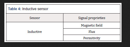
Inductive sensor
Are Also magnetic sensors sensors Inductive, These sensors create a small magnetic field at its tip and When the metal goes next to it disturbing the magnetic field, the cam sensor to capture this disturbance and sends a signal que can be interpreted by a circuit connected to the sensor (Table 4).
Table 4: Inductive sensor
Mechanic Sensor
These sensors are the ones who have the ability to detect the positions, movements or presence through mechanical means. Among the main applications, we can mention the presence of objects in a Certain place, the detection locks or door openings, and the limit switch sensor is one of the best known. The AIMS limit to Prevent sensing an engine to keep running even after the moving part reach the peak (Table 5).
Table 5: Mechanic Sensor
Optic Sensor
These sensors are also known as photovoltaic and use the propagation of light for its operation. The optical sensor is used to index objects and can also be used to measure the distance at which the object is in relation to the sensor. This type of sensor is used on elevator doors in computer mouse, bar code reader, in more modern vehicle reversing systems and many others (Table 6).
Table 6: Optic Sensor
Thermal sensor
This sensor gives a certain response when subjected to a temperature change. There are various types of thermal sensors and are several applications. The best-known thermal sensor is the thermometer that almost everyone has at home. It is used to measure body temperature. This type of temperature sensor is often used in environments where it is necessary to maintain a certain temperature, such as cold chambers. In this case, the sensor sends a response when it perceives that the temperature is outside of the ideal, and in accordance with this response refrigeration is switched off or activated(Table 7).
Table 7: Thermal sensor
It is important to know that there are specific sensors that fit within these mentioned groups which are the most common. There is a wide range of sensors for the most diverse applications. Following are some examples that may be used in devices embedded in the human body are presented. Indicative prices to be able to have an order of magnitude and make appropriate comparisons are presented [2,3]. The prices presented are based on historic benchmarking and experience of the author.
Proximity and Motion
The Distance ultrasonic sensor is capable of measuring distances of 2cm to 4m with great precision and low price. This module has a ready coupled to a receiver for measurement.
The reflection optical Reflective Phototransistor sensor is coupled in the same device has an infrared sensor (LED) and a phototransistor (receiver). It is specially designed to block light of other bands than the emitter itself, preventing ambient lighting interferences.
The Proximity Sensor Infrared is a photoelectric reflection module which includes an InfraRed (IR) transmitter and an IR receiver. This sensor has a longer range than traditional ones, ranging from 3 to 80 cm with the adjusting screw at the rear of the sensor.
The Absolute Orientation Sensor provides the possible to obtain the absolute position in three axes, useful to set up a project involving virtual reality [4-6].
The PIR Motion Presence Sensor can detect the movement of objects that are in an area up to 7 meters. If something is moving around in this area the alarm pin is activated.
The combined motion sensor on a single chip contains an accelerometer and a gyroscope MEMS type. They have 3-axis accelerometer and 3-axis gyroscope, providing 6 degrees of freedom (6DoF).
The obstacle IR sensor is a circuit composed by a transmitter, an IR receiver, and an IC comparator, which facilitates its connection with Arduino, PIC or Raspberry Pi, since its voltage is 3, 3-5V.
The Reed Magnetic sensor is a switch that works by magnetic field, closing the internal contacts when approaching. When taking the magnet, the contacts open again.
The Encoder speed sensor is used to perform engine speed measurements, pulse count and positioning controller. It can be used with many more drivers and boards such as Arduino, Raspberry Pi and PIC.
The Vibration sensor is designed to detect vibrations. Its applications are numerous but are mainly divided in a useful signal to process and a noise signal to remove. When the intensity is below the preset value (i.e., the value set at the potentiometer), the output is in a high state, otherwise the output is in the low state.
This Hall sensor has high sensitivity based on the Hall effect to measure magnetic fields around them. The magnetic signal is then converted into an electrical signal with high reliability and sensitivity and can be used in a very practical way with an Arduino. Alarms can be used in projects, accountants and other electronic circuits. The Grove magnetic sensor contains a reed switch on the board and can be used to set up alarm systems and proximity sensors based on magnetic fields.
The Vibration sensor Tilt Grove is used to detect movements and make the sign reading in a microcontroller as Arduino, Raspberry or Beaglebone plates and other applications in electronics design. The sensor can be used in monitoring systems and alarms systems, for example.
The gestures and RGB sensor are a plate with a sensor that provides ambient light measurement approach and signals. With Gesture Sensor and RGB it is possible to control a project, a computer design or a robot using only the movement of the hands.
The Distance Laser sensor is different from all the others: it uses a thin and invisible laser light source, and a circuit for detecting how long the light took to reach an object and return to the sensor. It can measure distances of between 30 and 1000mm with high degree of accuracy, has I2C and accepts power from 3 to 5V.
The analog line IR sensor varies the output value according to the amount of infrared light reflected to the sensor. When more light is detected by the IR receiver, the lower the voltage at the analog output.
The accelerometer module is a 12-bit resolution device with low power consumption, perfect for a virtual reality design using microcontrollers.
The Inductive Proximity Sensor is an NPN sensor capable of detecting metal objects up to 4mm away and generate a signal in the sensor output, which can be read by a microcontroller like Arduino.
The IR digital line sensor triggers the digital output according to IR light (infrared) received by the sensor. It is ideal for systems with only I / O available digital pin.
The 3-axis accelerometer has a new version provided now with a built-3.3V voltage regulator.
A Photo Interrupter Breakout Board was developed for easy connection to the component’s microcontroller. For complex projects involving accelerometer, gyroscope and magnetometer it is used an Absolute Orientation Sensor 9-DoF. It can be challenging to extract the necessary data of these sensors and convert them to a 3D world, requiring consolidating the data from these sensors, send them to I2C interface and saving work assemble complex algorithms or perform fine adjustments to extract the data needed.
For even more complex projects a 10DoF Sensor with Barometer, accelerometer, magnetometer and gyroscope is used. This is a powerful sensor IMU (Inertial Measurement Unit) that reaches 10 DOF, with 3-axis gyroscope, 3-axis accelerometer, 3-axis magnetometer and the pressure sensor and temperature.
Expected Price in March 2019 from €1.90 to €267.90
Temperature
The waterproof temperature sensor will allow you to take measurements in wet environments and wet with only one interface of one wire.
The regular temperature and humidity sensor allow temperature readings from 0 to 50° C and humidity 20 to 90%, widely used for projects with Arduino. The wider range temperature and humidity sensor allows temperature readings from -40 to +80° C and humidity from 0 to 100%, and very easy to use Arduino, Raspberry and other microcontrollers because it has only one output digital pin.
The temperature sensor with I2C communication is an accurate sensor, with typical accuracy of ± 0.25 ° C from -40° C to + 125° C + and resolution of 0.0625° C. The Temperature sensor is a sensor easy to use, communicating with the microcontroller via the I2C interface and sending temperature information in digital form, unlike traditional analog sensors. The Sensor Type K thermocouple with measuring range of -50 to 400° C is for use in multimeters and measurement equipment.
The temperature sensor can be a great option when looking for precision, and has easy communication with microcontrollers such as Arduino, PIC, ARM and Raspberry Pi. Widely used for home automation projects or even industrial.
The thermistor is a temperature sensor projects with widely used in microcontrollers, performing measurements in the range of -40 to 125° C based on a 10K Ohm NTC thermistor.
The temperature sensor Grove using a NTC thermistor for measuring the ambient temperature, generating an output voltage which is sent to the microcontroller.
The IR temperature sensor is a high-precision component that detects body temperature or objects by infrared without direct contact with the sensor is needed. It has already been calibrated at the factory and detects temperatures between -40 and 125° C with a precision of 0.5° C, still having multiple configurable user calibration methods.
The temperature and humidity sensor, for Sonoff is capable of measuring temperature and humidity providing data through its digital output. With its plug 4-pole, the sensor is perfectly compatible. The temperature and humidity sensor Son off have a resistive sensor capable of measuring temperature and a capacitive humidity sensor. Data is provided through its digital output. With its plug, the sensor is compatible with Sonoff TH10 / TH16. Sonoff is an affordable WiFi smart switch that provides users with smart home control.
The temperature sensor Waterproof Sonoff allows the functions similar to a thermostat, which can control any equipment according to the temperature.
The Digital Temperature Sensor performs temperature measurements accurately using only one pin of the controller.
The temperature and humidity sensor Grove is a module that contains a sensor on plate being connected to the microcontroller through a standard 4-pin cable Grove. This sensor comes pre-calibrated and is characterized by low power consumption and ease of use.
Expected Price in March 2019 from €2.40 to €80.90
Luminosity
The Brightness 5mm LDR (Light Dependent Resistor) sensor is a component whose resistance varies with the intensity of light. The lighter falls on the component, the lower the resistance. The light sensor can be used in projects with Arduino and other microcontrollers for alarms, home automation, motion, etc.
The Infrared (IR) receiver is useful in electronic projects such as motor control, lighting, alarms and circuits in general. It is user friendly with microcontroller circuit using Arduino, PIC or Raspberry Pi.
The IR Receiver Module is used in electronics design, remote control systems and alarms, for example.
The ambient light sensor module is a simple module to use but very powerful, as it has greater precision than standard modules using LDR (light dependent resistors). The sensor used is NPN phototransistor and the module has an analog output signal that can be read for example by a plate as Arduino. The higher the incidence of light, the higher the value in the output.
The photo Switch is an optical switch that operates with infrared, and on one side have an LED IR emitter establishing a light beam which is detected by the IR receiver on the opposite side. The distance between the transmitter and the receiver is 10mm.
The LDR Light Sensor (Light Dependent Resistor) is designed to detect light and has a digital and analog output that can be connected directly to a microcontroller as the Arduino.
The Infrared Phototransistor LED 5mm receiver is sensitive to infrared light and acts as a receiver of this type of light for use in electronics design as motor control, lighting, alarms and circuits in general. It is easy use with microcontroller circuit using Arduino, PIC or Raspberry Pi.
The UV Sensor is capable of detecting UV solar radiation using a simple chip. It can be easily configured for projects with Arduino to monitor UV Index, analyze UV-A lamps or DIY projects as plant growth analysis.
The Lux Light sensor can determine the amount of light (measured in lux), which is focusing on the sensor, and show that result in a display or trigger microcontroller ports in certain situations to light. Expected Price in March 2019 from €0.90 to €85.90.
Moisture
The humidity sensor Grove is composed of a rod and sends information to the microcontroller according to the humidity level detected by the sensor.
The Hygrometer Humidity Sensor is designed to detect the humidity changes, and when it is dry the sensor output is in the high state and low state when in wet.
The Rain Sensor is used to monitor a variety of weather conditions, but it can be used in liquid drops. When the surface is dry the sensor output is in a high state and when there is a liquid drop the sensor, output is in down state. Expected Price in March 2019 from €9.90 to €13.90.
Temperature and Moisture
The Temperature and Humidity High Precision Sensor and I2C communication with the microcontroller for use in electronics design, weather stations, room temperature control and medical equipment, among others. The sensor has 14-bit resolution and accuracy of 2% humidity and temperature of 0.2° C, providing accurate and reliable information as well as an extremely low power consumption in sleep mode. Expected Price in March 2019 around €65.00.
Chain
The Current Sensor Non-Invasive is an optimal device to measure AC current and is not invasive. It is widely used in projects with home automation Arduino like electrical current meters, protection of AC motors, lighting and others, but the non-invasive propriety is a boost to medical application.
The Current sensor performs current measurements accurately since it uses the Hall effect to detect the magnetic field generated by a current generating at the module output (OUT pin), a proportional voltage 66mV / A.
The DC Current Sensor provides measurements in circuits with DC voltage between 0 and 26V with DC current sensor, a I2C communication module and easy integration with devices such as Arduino, and other I2C interface. Expected Price in March 2019 from €26.90 to €58.90.
Touch
The Touch Sensor Capacitive is a component capable of detecting touches. Its operation is very simple: by touching the indicated region, the output of the sensor is activated. Without touching the sensor, there is no activity on output. It can be used as replacement of a push button.
The flexible sensor is a sensor of Sparkfun whose resistance varies as the sensor is bent. The greater the force applied, the greater the resistance in the sensor output.
The Force Sensor Resistive can make measurements between 100 g and 10 kg, depending on the force applied in the detection area (approximately a 15mm circle). Expected Price in March 2019 from €8.90 to €74.90.
Biometric
The Heart Rate Sensor allows to obtain data very useful when riding an exercise routine, studying daily physical activity or even for teaching purposes. The heart monitor pulse sensor performs reading of the heartbeat using an optical sensor amplified and sends this data to the microcontroller as the Arduino via a single signal pin.
The MyoWare Power Shield is a card designed for use with the Muscular Sensor MyoWare and uses two batteries. The Fingerprint Sensor can be used in projects with high complexity existing in this process.
The Muscular Expander Electrodes MyoWare Sensor allows you to place up to two electrodes directly on the board, being an interesting option for wearable designs (wearables). However, you often need a larger number of electrodes, or more distance between the electrodes and the sensor, and that’s where the Expander MyoWare electrodes. With Expander Electrodes Myoware, you can connectup to three electrodes using the cable MyoWare sensors (not included) connected to the expander through a P2 plug.
The Biomedical Electrode is the component responsible for forwarding to the sensor the electric signal captured during the movement of muscles. It can be connected directly to the Muscular Sensor or cable sensors.
The Sensor Muscular Myoware is a control device with the strength of your muscles. This is a plate designed for use with Arduino and using a sensor electromyography (EMG), which measures the electrical activity of a muscle. Muscular Myoware sensor generates at the output a voltage between 0 volts, and Vs, where Vs is the sensor voltage. The greater muscle activity, the higher the voltage at the output.
The cable Sensor is an accessory to be used in conjunction with the Expander electrodes and allows you to connect up to 3 electrodes in muscle sensor.
The strike sensor and Heartbeat Oximeter is a module consisting of two LEDs and a photodetector circuits that detect heart beats and indirectly measure the amount of oxygen in the blood. The sensor is suitable for projects in the medical field, fitness and wearables, among others. Expected Price in March 2019 from €12.90 to €374.90.
Barometric
The Pressure and temperature sensor have gains in terms of accuracy and power consumption beyond the size 63% smaller, making common their use in mobile and portable devices.
The Pressure and temperature sensor are fully compliant in terms of firmware and interface, including using the same Arduino library. It is a compact sensor with low power consumption (about 0.5μA), being a good choice for projects powered by batteries.
The Air Pressure Sensor measuring range of 0 to 40kPa and using MEMS technology miniaturization of components in a package DIP (dual in-line package). Expected Price in March 2019 around €20.00.
Others
TThe Water Flow Sensor measure water flow for your electronic projects is now no longer a problem with this Water Flow Sensor. It is installed in line with the pipe to measure the amount of water flowing through it, sending PWM pulses to your Arduino and Raspberry Pi for example. Expected Price in March 2019 around €35.00.
The Load Cell Weight Sensor uses the weight sensor load cell together with the module and build its own scale based on Arduino, Raspberry, or other PIC microcontroller. Expected Price in March 2019 around €20.00.
The Water Level Sensor is a liquid level sensor for use in water tanks, reservoirs, tanks and other containers. The level sensor functions as a power switch that can trigger switches, pumps, lamps or send a signal to the microcontroller as the Arduino, Raspberry Pi or Pic. Expected Price in March 2019 around €15.00.
The Color sensor detects the color of objects quickly and accurately with the color recognition sensor. The sensor recognizes light levels RGB (Red, Green and Blue, or red, green and blue) and sends this data to a microcontroller as Arduino, Raspberry, PIC and other models, allowing you to create efficient color detection systems. The Color RGB sensor with IR filter can recognize colors quickly and effectively. Based on chip, this sensor has RGB light sensors which together with the IR filter minimizes the influence of the IR spectrum, such as lights, leaving a much more accurate measurement. Expected Price in March 2019 around €65.00.
The sound sensor Grove is a plate with a microphone that detects the sound system and generates a variable signal at the output according to the intensity of the captured sound. Expected Price in March 2019 around €40.00.
Conclusions
There is a wide range of diferente sensors with diferente applications, advantages and strenghts. Knowing what best suits a real situation is crucial to extend life long. Also, it is important to understand how the sensor communicates the acquired data in order to find the appropriate acquisition and processing signal board.
Read More About this Article: https://biomedgrid.com/fulltext/volume2/a-guide-to-select-sensors-for-biomedical-propose.000583.php
For more about: Journals on Biomedical Science :Biomed Grid
#biomedgrid#Journals on Biomedical Imaging#Journals on Medical Microbiology#Journals on Medical Casereports#Journals on Medical drug and theraputics#Open Access journals on surgery
0 notes
Text
N1-§2 What is the Structure of a Solid-State Relay?

The solid-state relays are four-terminal active devices, two of the four terminals are input control terminals, and the other two terminals are output control terminals. Although the types and specifications of SSR switches are numerous, their structures are similar and consist mainly of three parts (as shown in Figure 2.1): Input Circuit (Control Circuit), Drive Circuit, and Output Circuit (Controlled Circuit).
Input Circuit:
The Input Circuit of the solid state relay, also called control circuit, provides a loop for the input control signal, making the control signal as a trigger source for the solid state relay. According to different input voltage types, the input circuit can be divided into three types, DC input circuit, AC input circuit and AC/DC input circuit.
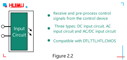
The DC input circuit can be further divided into Resistive Input Circuit and Constant Current Input Circuit. 1) The Resistive Input Circuit, whose input current increases linearly with increasing input voltage, and vice versa. If the control signal has a fixed control voltage, the resistor input circuit should be selected. 2) The Constant Current Input Circuit. When the input voltage of the constant current input circuit reaches a certain value, the current will no longer increase obviously as the voltage increases. This feature allows the use of a constant current input solid state relay over a fairly wide input voltage range. For example, when the voltage variation range of the control signal is kind of large (e.g., 3~32V), the DC solid state relay with constant current input circuit will be recommended to ensure that the DC solid-state relay can work reliably over the entire input voltage range. Some of these input control circuits have positive and negative logic control, inverting and other functions, as well as the compatibility of logic circuits. Thus, solid state relays can be easily connected to TTL circuits (Transistor-Transistor Logic circuits), CMOS circuits (Complementary Metal Oxide Semiconductor circuits), DTL circuits (Diode-Transistor Logic circuits), and HTL circuits (High Threshold Logic circuits). At present, DTL has been gradually replaced by TTL, and HTL has been replaced by CMOS. And if the Pulse Width Modulated signal (PWM) is used as input signal, the ON/OFF switching frequency of the AC load supply should be set to less than 10Hz, or the output switching rate of the output circuit of the AC SSR cannot keep up with it.
Drive Circuit:
The driving circuit of solid state relay includes three parts: Isolation Coupling Circuit, Function Circuit and Trigger Circuit. However, according to the actual needs of solid-state relay, only one/two of these parts may be included.

1. Isolated Coupling Circuit:
The isolation and coupling methods for I/O circuits (Input / Output circuit) of solid-state relays currently use two ways, Optocoupler Circuits and High Frequency Transformer Circuits. 1) Optocoupler (also called photocoupler, optical coupler, opto-isolator, or optical isolator) is opaquely packaged with an infrared LED (Light-Emitting Diode) and an optical sensor to achieve isolated control between "control side" and "load side", because there is no electrical connection or physical connection between the " Light emitter " and the " Light sensor" except the beam. The types of “source-sensor” combinations normally include: "LED-Phototransistor" (Phototransistor Coupler), "LED-Triac" (Phototriac Coupler), and "LED-Photodiode array" (the stack of photodiodes is used to drive a pair of MOSFETs or an IGBT). 2) The high frequency transformer coupling circuit uses a high frequency transformer to convert the control signal at the input to the drive signal at the output. The detail process is, the input control signal produces a self-oscillating high frequency signal that will be transmitted through the transformer core to the transformer secondary, and after processing by the detection/rectification circuit and the logic circuit, the signal will eventually become the drive signal to drive the trigger circuit.
2. Functional Circuit:
The functional circuit may include various functional circuits, such as detection circuit, rectifier circuit, zero-crossing circuit, acceleration circuit, protection circuit, display circuit, etc.
3. Trigger Circuit:
The trigger circuit is used to provide a trigger signal to the output circuit.
Output Circuit:
The output circuit of the solid-state relay is controlled by a trigger signal to enable on/off switching of the load power supplies.
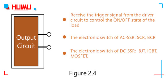
The output circuit is mainly composed of an output component (chip) and an absorption loop (which acts as a transient suppressor), and sometimes includes a feedback circuit. Up to now, the output component of solid state relays mainly include:Bipolar Junction Transistor(Bipolar Transistor or BJT, which divided of two types, PNP and NPN), Thyristor (Silicon Controlled Rectifier or SCR), Triac (Bi-directional Triode, Bi-directional thyristor, Bi-directional Controlled Rectifier or BCR), Metal-Oxide-Semiconductor Field-Effect Transistor (MOSFET), Insulated Gate Bipolar Transistor(IGBT), Silicon-Carbide MOSFET (SIC MOSFET, a kind of wide bandgap transistor with the industrial grade highest operating junction temperature of 200°C, low power consumption and compact size), and so on. The output circuit of the solid state relay can be divided into three types: DC output circuit, AC output circuit and AC/DC output circuit. The DC output circuit typically uses bipolar component (such as IGBT or MOSFET) as the output component, and the AC output circuit usually uses two Thyristors or one Triac as the output component.
0 notes
Link
Sell TOKO TK10659MTL New Stock #TK10659MTL TOKO TK10659MTL New , TK10659MTL pictures, TK10659MTL price, #TK10659MTL supplier ------------------------------------------------------------------- Email: [email protected] https://www.slw-ele.com/tk10659mtl.html ------------------------------------------------------------------- Shunlongwei Inspected Every TK10659MTL Before Ship, All TK10659MTL with 6 months warranty. Part Number Manufacturer Packaging Descript Qty TP-3142S2OmronTouch panelOmron Touch panel TP-3142S2 TP-3142S2 touchscreen 183 PCSZ85C3008VSGZILOGPLCC44IC 2 CHANNEL(S), 4.1M bps, MULTI PROTOCOL CONTROLLER, PQCC44, PLASTIC, LCC-44, Serial IO/Communication Controller 2080 PCSTLP598GATOSHIBADIP6Solid State Relay, TRANSISTOR OUTPUT SOLID STATE RELAY, 2500 V ISOLATION-MAX, PLASTIC, 11-7A8, DIP-6 10460 PCSSSM3J15FVTOSHIBASOT-723 64087 PCSS-80824CLPF-B6JTFGSIISNT-4APower Supply Support Circuit, Fixed, 1 Channel, +2.4VV, CMOS, PDSO4, LEAD FREE, SNT-4 116713 PCSRT9809-29CV//PVRiChTekSOT23 1240 PCSLM3200TLXNSBGA10IC 1.2 A SWITCHING REGULATOR, 2200 kHz SWITCHING FREQ-MAX, PBGA10, ROHS COMPLIANT, THIN MICRO SMD, 10 PIN, Switching Regulator or Controller 9385 PCSCX27465-12MNDSPEEDPBGA624 4162 PCSBC847PN E6327INFINEONSOT-363 18903 PCSDSS4140V-7DIODESSOT-563Small Signal Bipolar Transistor, 1A I(C), 40V V(BR)CEO, 1-Element, NPN, Silicon, GREEN, ULTRA SMALL, PLASTIC PACKAGE-6 15090 PCS
0 notes
Text
Small Signal Transistors Market 2018 International Industry Growth Rate And Key Opportunities
Global Small Signal Transistors Market: Introduction
Small signal transistors are transistors or solid state components used to generate electric signals, control and amplify them. Small signal transistors are of two types, namely NPN and PNP transistors. Small signal transistors can be used as amplifiers and switches for various applications. Nowadays, small signal transistors are offered with the latest silicon planar technology that ensures fast switching performance high reliability. Usually for small signal transistors the hFE values range between 10 and 500, whereas the IC ratings of small signal transistors ranges from 80 to 600 mA (milliamperes).
Small signal transistors can be used for amplifying small signals such as using mA of current and a few volts. Whereas one should use power transistor in place of small signal transistor when using larger voltage and current. Small signal transistors can withstand high voltages and temperatures and therefore are ideal components UPS (Uninterruptible Power Supply) and PS (Power Supply Unit).
The small signal transistor segment is becoming further extensive in more small packages with numerous combination of resistance value for space saving. Some of the applications of small signal transistors in different segments are LED diode driver, relay driver, bias supply circuits, infrared diode amplifier, timer circuits, audio mute function, on/off switches for general use and telecom wire line interface circuits.
Global Small Signal Transistors Market: Dynamics
Automation helps in controlling the systems effectively and efficiently and hence it is being adopted in various industries at a very rapid pace. Thus implementation of automation is one of the major trends in small signal transistor market. Hence increasing automation in different industries is anticipated to drive the growth of the small signal transistor market during the forecast period.
The increased switching speed of small signal transistor helps to reduce the noise, which further reduces the energy consumption, fueling the growth of the small signal transistors market over the projected period. Due to the benefits offered by IoT there is growth in demand of IoT in different sectors such as consumer electronics, communication industries automotive and other industrial purposes. Thus IoT requires low power small signal transistors which consumes very less power.
Thus increasing adoption of IoT, will in turn increase the demand of small signal transistor during the forecast period. However, decrease in sales of electronic gadgets such as tablets and desktops leads to low demand of small signal transistors, is hindering the growth of the market over the projected period of time.
For Detailed Insights On Enhancing Your Product Footprint, Request For Sample Report Here @ https://www.persistencemarketresearch.com/samples/27973
Global Small Signal Transistors Market: Segmentation
The global small signal transistors market can be segmented on the basis of type, application, and region.
Small Signal Transistors market by type:
PNP NPN
Small Signal Transistors market by application:
Automotive application Industrial applications Consumer electronics Communications Others
Global Small Signal Transistors Market: Regional Outlook
Geographically, the small signal transistors market can be segmented into North America, Western Europe, Latin America, Eastern Europe, Asia Pacific excluding Japan (APEJ), Middle East and Africa (MEA), and Japan.
Asia Pacific is expected to be an emerging market, owing to increasing demand from emerging economies such as India and China. Increasing urbanization in these countries is providing growth opportunities for the small signal transistors market.
The Asia Pacific region is expected to hold the largest market share of the small signal transistor market over the forecast period. The share of small signal transistor market in APAC region is anticipated to be followed by the Europe and North America’s market share owing to the increasing demand of IoT in this regions. The Asia Pacific is expected to dominate the small signal transistor market throughout the forecast period.
Regional analysis includes:
North America small signal transistor market U.S. Canada Latin America small signal transistor market Argentina Mexico Brazil Rest of Latin America Western Europe small signal transistor market Germany France U.K. Spain Italy Nordic Benelux Rest of Western Europe Eastern Europe small signal transistor market Poland Russia Asia Pacific small signal transistor market India ASEAN Australia and New Zealand Rest of SEA and Others of APAC Japan small signal transistor market China small signal transistor market Middle East and Africa small signal transistor market GCC Countries North Africa South Africa Rest of MEA
The power capacitors market report is a compilation of first-hand information, qualitative and quantitative assessment by industry analysts, and inputs from industry experts and industry participants across the value chain.
It provides an in-depth analysis of parent market trends, macro-economic indicators, and governing factors, along with market attractiveness as per segment. It also maps the qualitative impact of various market factors on market segments and geographies.
For Critical Insights On Global Small Signal Transistors Market, Request For Customization Here @ https://www.persistencemarketresearch.com/request-customization/27973
Global Small Signal Transistors Market: Competition Landscape
Key Vendors
Some of the key vendors in the small signal transistors market are :
Renesas Electronics, Infineon Technologies, NXP Semiconductors, STMicroelectronics, Maxim Integrated, Central Semiconductor Corp., Diodes Inc., Taiwan Semiconductor Manufacturing Company
The report covers an exhaustive analysis on:
Market Segments
Market Dynamics Historical Actual Market Size, 2013-2017 Market Size and Forecast 2018 to 2028 Supply and Demand Value Chain Current Trends/Issues/Challenges Competition and Companies Involved Technology Value Chain Market Drivers and Restraints
#Small Signal Transistors Market Growth#Small Signal Transistors Market Opportunities#Small Signal Transistors Market Challenges#Small Signal Transistors Market Drivers#Small Signal Transistors Market
0 notes
Link
relays are electromechanical devices that use a magnet to control a combination of movable contacts from an open position to a closed position. non latching relay or bistable switches are switching devices with 2 stable states for switching of all reasonably electrical loads. Those switches operate while not power consumption in operating switch-on position and with a really small consumption per pole.
0 notes