#power relay 120v
Explore tagged Tumblr posts
Visit Tumblr Blog
Explore Tumblr blogs with no restrictions, modern design and the best experience.
Last Seen Tumblr Blogs


Fun Fact
Tumblr.com rank in the US is 25.
Text
https://www.futureelectronics.com/p/electromechanical--relays--power-relays/2-1415898-3-te-connectivity-5076008
PCB Mount Power Relay, Pin PCB Relay, Power windows, Power relay socket
RT1 Series SPST (1 Form A) 16 A 12 V PCB Mount General Purpose Power Relay
#TE Connectivity#1415898-3#Relays#Power Relays#Tyco Electronics#Socket power relay#PCB SPST#latching#PCB Mount#Pin PCB Relay#Power windows#Power relay socket#Power relay switch#Solid state relay#Power relay module#power relay 120v
1 note
·
View note
Text
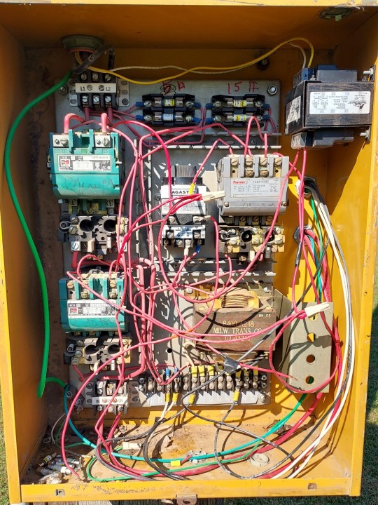


We did it, we fucking did it.
This is a 1986 Federal Signal Thunderbolt 1000BSC, currently in service in Julian, Nebraska. This siren used to belong to Cooper Nuclear Power Plant and was removed and sold when they upgraded their system. This replaced a Federal Signal Model 5B. This siren has been having issues for a good few years due to a piss poor wiring job on the RCM and lack of maintenance. I started working on this alongside the town hall board in late November 2023, I couldn't get the control box to work, so I contacted my siren enthusiast buddies in Omaha to help out. After two weeks of them getting everything corrected and functional, it was time to put it back together. Saturday, December 16th, 2023, was the final day for all major work to be completed. A new 120v relay was added for a more effective way of sounding off the siren rather than the transformer seen. At 4:26 PM CST, the Sheriff's office sounded the siren for the final test. It roars like a Thunderbolt once again. The siren will be maintained by me and my buddies from Omaha from now on.
27 notes
·
View notes
Text
Reading more about inrush current control techniques now, all I knew before this was that you use Negative Temperature Coefficient parts to control it without affecting overall efficiency too much.
I've never had to design a board that drew much power, or didn't just use an off the shelf power supply. Power supply design is black magic so even major companies usually just buy certified open frame units to avoid redoing a ton of regulatory work, it's what's best for everyone. All the appliances at First Job just had a 24V Great Wall open frame units jammed in there, plus consumer 12V supplies for the network gear.
You can do some clever things involving having the NTC take itself out of the loop with a relay and a zener diode if you have really high efficiency targets to hit or you don't want to fry your NTC as the current picks up. I love these kinds of self-contained feedback tricks, they're super handy. And of course there's digital current controllers for high precision applications.
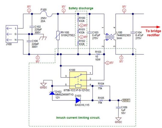
Figure 5 shows the relay circuit for a 1kW power supply. The relay is initially turned off. During power up, the input current flows through a 10Ω/10W cement resistor. Once the power supply is energized, a regulated bias voltage, 12V2, turns on the relay to minimize the power dissipation on the current-limiting circuit during normal operation.
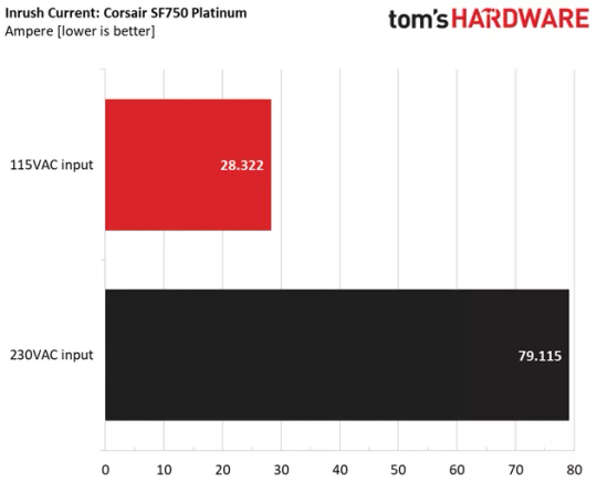
Anyway. Reading specs it looks like there's a systematically higher inrush current in computer PSU's when you connect them to 230V, which is probably just Ohm's Law at work. A lot of supplies with really good 110V inrush limiting have utterly dogshit 230V inrush limiting.
An interesting problem I realize this might cause is that, because most tech reviewers are Americans with 110V, they won't pick this up as often. E.g. the highly recommended SF750 from Corsair has fantastic 120V inrush of ~30A but on 230W it's almost 80A, which would definitely trip a lot of home breakers.
10 notes
·
View notes
Text
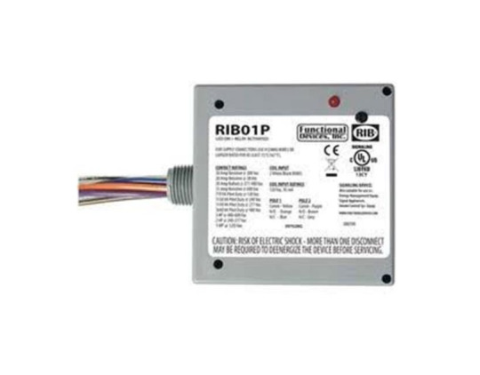
Functional Devices Rib01P30-120V 30A Dpst-N/O Pwrcntrlrly | PartsHnC

The Functional Devices RIB01P30 is a heavy-duty power control relay designed for HVAC, lighting, and industrial applications. Operating at 120V, it features a 30A current rating and a double-pole, single-throw (DPST) normally open (N/O) configuration for controlling larger loads. Built with durable materials, it ensures reliable performance and long operational life.
#Functionaldevices#hvacparts#airconditionerparts#furnaceparts#partshncbuzz#partshnc#RIB01P30#Powercontrol
0 notes
Text
Functional Devices Rib01P-120V 20A Dpdt Power Control Relay - PartsHnC
The Functional Devices RIB01P Power Control Relay is a versatile and reliable solution for controlling electrical loads. Designed for a 120V AC input, this relay features a 20A DPDT (Double Pole Double Throw) contact configuration, offering flexible switching capabilities for various applications. It is commonly used in HVAC systems, lighting controls, and general power management.
#partshnc#partshncbuzz#airconditionerparts#furnaceparts#hvacparts#FunctionalDevices#FunctionalDevicesParts#RIB01P#PowerControlRelay
0 notes
Text
Resideo RA832A1066 Transformer Relay | PartsHnC

Manufacturer Name: Resideo Product Number: RA832A1066 OEM Part Number: RA832A1066
The Resideo RA832A1066 Transformer Relay is a durable component used to control HVAC systems and other electrical applications. This DPST (Double Pole Single Throw) relay has a 120V power supply and a 24V AC coil, making it suitable for activating or deactivating HVAC equipment. It uses a control circuit with a two-wire connector for easy installation.
0 notes
Text
Turbochef NGC-3005 Solid State Dual Voltage Relay, 120/240V/40A | PartsFe

Manufacturer Name:Turbochef
Product Number: NGC-3005
OEM Part Number:NGC-3005
The Turbochef NGC-3005 Solid State Dual Voltage Relay is a high-quality replacement part designed for commercial kitchen equipment. It operates at both 120V and 240V with a capacity of 40A, ensuring compatibility with various power configurations.
0 notes
Text
Understanding the Basics of Control Transformers: A Comprehensive Guide

In the world of electrical engineering, control transformers are vital components that play a crucial role in various applications, particularly in industrial settings. These specialized transformers differ from power transformers in their design and function, serving the specific purpose of supplying power to control circuits, such as relays, timers, and contactors. This comprehensive guide aims to provide an in-depth understanding of control transformers, their functions, applications, and essential considerations in selecting and using them effectively.
Control Transformer Basics
Control transformers, often referred to as machine tool transformers or industrial control transformers, are designed to provide a stable, low-voltage power supply to control circuits. These circuits are commonly used to operate and control electromechanical devices, such as motors, solenoids, and heating elements. Unlike power transformers, which are used to step up or step down voltage for transmission and distribution, control transformers primarily step down the voltage to a lower level suitable for control and automation systems.
Control transformers are characterized by several key attributes:
Low Voltage Output: They typically provide low voltage output, often in the range of 24V, 120V, or 240V, although custom voltage levels can be designed to suit specific requirements.
Isolation: Control transformers are designed to provide electrical isolation between the primary (input) and secondary (output) windings. This ensures that the control circuit remains separate from the power circuit, improving safety and preventing electrical interference.
Efficiency: These transformers are built to be energy-efficient and generate minimal heat, which is especially important for continuous operation in industrial environments.
Compact Size: Control transformers are generally more compact and lightweight compared to power transformers, making them easier to integrate into control panels and enclosures.
Applications of Control Transformers
Control transformers find extensive use in various applications across industries, where precise control and operation of electrical systems are necessary. Some common applications include:
Motor Control: Control transformers are often used in motor control centers to provide the necessary low-voltage power for motor starters and control devices.
Heating Systems: They are employed in electric heating systems to control heating elements, such as those used in ovens, furnaces, and industrial heaters.
Lighting Control: Control transformers play a role in lighting control systems, allowing for the efficient operation of relays and timers in lighting circuits.
Automation and Robotics: In industrial automation and robotics, these transformers provide power for relays and solenoids that control various processes and machinery.
HVAC Systems: Heating, ventilation, and air conditioning systems often use control transformers for managing the operation of fans, dampers, and other components.
Selecting the Right Control Transformer
Selecting the appropriate control transformer is essential to ensure the reliable and safe operation of electrical control systems. When choosing a control transformer, consider the following factors:
Voltage Rating: Determine the voltage requirements of your control circuit. Control transformers come in various voltage ratings, and selecting the right one is crucial to avoid overloading or underpowering the system.
KVA Rating: The kVA (kilovolt-ampere) rating of the transformer indicates its capacity to deliver power. Calculate the total kVA load of your control circuit and select a transformer with a suitable kVA rating to handle the load.
Isolation: Ensure that the transformer provides adequate electrical isolation between the primary and secondary windings to prevent interference and enhance safety.
Mounting and Size: Consider the available space and the mounting requirements within your control panel or enclosure. Control transformers come in various sizes and mounting options, such as panel-mounted or DIN rail-mounted.
Environmental Conditions: If the transformer will be exposed to harsh environmental conditions, such as extreme temperatures or high humidity, choose a transformer designed to withstand such conditions.
Efficiency: Opt for an energy-efficient control transformer to minimize energy consumption and reduce heat generation, particularly in continuous operation scenarios.
Compliance: Ensure that the selected transformer meets relevant industry standards and certifications, such as UL, CE, or RoHS, to guarantee its safety and performance.
Installation and Maintenance
Proper installation and maintenance of control transformers are essential for their longevity and trouble-free operation. Follow these guidelines:
Proper Mounting: Mount the transformer securely to prevent vibration or movement that can lead to wear and tear.
Cooling: Ensure adequate ventilation around the transformer to prevent overheating. Proper ventilation is especially important for transformers operating at or near their rated capacity.
Periodic Inspection: Regularly inspect the transformer for signs of wear, loose connections, or damage. Address any issues promptly to avoid potential problems.
Environmental Considerations: Protect the transformer from exposure to excessive moisture, dust, or corrosive substances.
Qualified Maintenance: If maintenance or repairs are required, it is advisable to seek the assistance of a qualified electrician or technician with experience in control transformer systems.
In conclusion, control transformers are integral components in electrical control systems, providing the necessary low-voltage power for the efficient and safe operation of various devices and machinery. Understanding their functions, applications, and the factors to consider when selecting and maintaining them is essential for ensuring the reliability and longevity of control circuits in industrial and commercial settings. With the right control transformer and proper care, electrical control systems can operate seamlessly and efficiently, contributing to the success of diverse industries.
0 notes
Text
CIRCUIT BREAKER VS. DISCONNECT SWITCH
Is it possible to use a circuit breaker as a switch interchangeably, or are they separate entities?
Circuit breakers and switches are not new technologies; in fact, Thomas Edison first developed the idea for a circuit breaker in 1879.
These items are often taken for granted as they work behind the scenes, and yet they are crucial for safety in homes and in industry.
For industrial purposes, both the switch and the circuit breaker need to be able to handle a higher capacity of electricity than a residential one would.
But what are the differences between a switch and a circuit breaker?
A Disconnect Switch
An electrical switch serves the purpose of controlling the flow of electrical current to a circuit. It can be used to both remove the flow of the current or to initiate it. There are many types of switches. Relays and contactors are two other types that are commonly used in electrical controls.
A disconnect switch performs the task of manually cutting or reconnecting power from an electrical supply by creating or closing an air insulation gap between two conduction points.
They’re known as binary devices, which essentially means it has two states, open (O) and closed (|).
A Circuit Breaker
A circuit breaker is a safety device to prevent damage to devices in a circuit, such as electric motors, and wiring when the current flowing through the electrical circuit supersedes its design limits. It does this by removing the current from a circuit when an unsafe condition arises. Unlike a switch, a circuit breaker automatically does this and shuts off the power immediately, or darn close to immediately. In this way it works as an automatic service protection device.
A switch is typically used as an isolator, turning power on and off to a particular device. A circuit breaker, on the other hand, can be used to protect a circuit that contains many switches or devices. An exception to this is a disconnect switch, which is used to connect or disconnect power to an entire control panel, or machine.
Simply put, a switch is designed to switch power on and off, a circuit breaker “breaks” the circuit in an overload or fault condition. Switches switch and breakers break. These differences are crucial to understanding their safety and practicality.
The BIG Difference
When it’s all said and done, a big reason NOT to use a circuit breaker as a disconnect switch is a question of endurance. Disconnect switches are designed for a high number of operations, how many times the disconnect switch is turned on and off . Circuit breakers are typically not rated for nearly the same amount of operations.
A miniature circuit breaker is a deceiving simple device. It is a much more complicated device, with more parts, than a switch. Cycling a breaker on and off numerous times will result in its eventual failure.
However...
Circuit breakers can be rated for switching duty for lighting circuits. Circuit breakers applied in 120V or 277V fluorescent lighting circuits must be marked SWD or HID. SWD stands for Switching Duty. HID signifies rated for High Intensity Discharge lighting. The UL489 Standard for MCBs states that an SWD circuit breaker can be rated up to 20A, no more. HID breakers are rated up to 50A.
Which Will It Be Then?
The question still begs, even though it’s obvious by now, can you use a circuit breaker like a switch in an industrial control panel? It’s quite evident that though they share a similar function on a basic level, they are two separate entities.
Circuit breakers may work as effective as safe switches, but they are not switches. They are not interchangeable. Therefore, using a circuit breaker as a switch is not recommended.
Can I Use A Switch In Place Of A Circuit Breaker?
No. Don’t ever do this. A switch cannot detect and interrupt an overload or fault condition. This can lead to an unsafe or potentially dangerous condition, putting equipment and more importantly, people at risk.
0 notes
Text
What is Electrical Control Panel?
Electrical control panels are designed and wont to control mechanical equipment. Each one is designed for a particular equipment arrangement and includes devices that permit an operator to control specified equipment. Electrical panel managed electricity control in every industry.
It’s difficult to clarify all combinations because every industry and most Control Panel Manufacturer Companies have defined part preferences.
Type of Electric Control Panel
MCC Panel
PCC Panel
APFC Panel
LT Panel
Safety Ratings
Short Circuit Current Rating (SCCR) = 5kA
3rd Party Safety Certification = UL508A (cULus)
Enclosure Ratings
Material: 304 Stainless Steel
NEMA Rating: NEMA 4X Outdoor
Mounting: Wall Mount
Door Mechanism: Lockable Handle with 3 Point Door Latch
Main Power
Incoming Power
Outgoing 480V Power
480V 3 Phase through a Main Circuit Breaker
480V 5.0 HP Fan through a Motor Starter
480V 1.0 HP Pump through a Motor Starter

Control Power
120V and 24VDC
480V-120V Transformer
120V-24VDC Power Supply
Outgoing 120V Power
Chemical Pump through a Power Relay
Why Choose Expert Engineers
Expert Engineers is professionally managed control panel manufacturing company, engaged in fabricating state of the art and tailor-made low voltage electrical switchboard panels, electrical control panel, catering to the needs of your building, power and other industrial verticals. The skilled and professional electrical engineers employed in the company leave no stones upturned to fabricate cutting edge panel solutions to empower and enlighten the lives of the people.

We deal in array of quality products including
Auto transformer starter,
Power and distribution boards,
Cable trays, Cable Raceways,
SCADA systems and many more.
#Electrical control panel#Control panel manufacturers#Control panel manufacturers in india#Panel manufacturing#Control Panels Manufacturer in Delhi#Electrical Control Panel Manufacturer#Panel Manufacturing Company
2 notes
·
View notes
Text
10 Things Everyone Hates About AC repair in Milpitas
™20 Finest Shopper Service Jobs In Salinas, Ca
Then, customers needn't have to differentiate if the DC power is available on the hot terminal or at the neutral terminal of socket 172, and thus won't endure a wrong polarity problem. For instance, if a consumer plugs any AC device, similar to an AC to DC energy adapter, having simply two plug terminals, e.g. sizzling and impartial, into socket 172, there will be no energy quick issues because the hot and neutral terminals are at the similar DC potential. 120V AC/DC circuit breaker circuit 200 additional includes two energy output wires, a power output wire 260 tailored to couple to AC scorching wire a hundred and forty four and a impartial output wire 265 adapted to couple to AC neutral wire 154. DC safety device 230 and DC voltage detector circuit 235 include local floor 126 connections. Single-pole switch 220 can be managed manually to enable the DC energy enter to chose particular person 120V AC/DC circuit breaker circuit 200, e.g. 120V AC/DC circuit breaker circuit 136, in service panel a hundred and five.

When single-pole change 220 is switched off, then solely AC energy shall be output from 120V AC/DC circuit breaker circuit 200. 1 and 5, AC & DC security device 527 is configured to watch, on the service panel, an AC and/or DC power surge and/or irregular thermal situation related to a minimum of one energy connection wire, e.g. AC hot wire 144 and/or AC neutral wire 154, at energy output wire 260 and/or power output wire 265 respectively. 2 depicts a simplified exemplary schematic of a 120V AC/DC circuit breaker circuit 200 configured to adaptively select between AC energy enter 118 and DC power enter 121 for supply of AC energy or DC power to AC scorching wire a hundred and forty four and AC impartial wire 154 as depicted in FIG. 1 and a couple of, 120V AC/DC circuit breaker circuit 200 could correspond to 120V AC/DC circuit breaker circuit 136 and/or to 120V AC/DC circuit breaker circuit 138.
The first power wire is linked between a socket and the circuit breaker when the circuit breaker is put click here in in a service panel of the building. The circuit breaker additional includes a detection circuit adapted to watch a voltage stage of the DC energy enter. three depicts a simplified exemplary schematic of a 240V AC/DC circuit breaker circuit 300 configured to adaptively select between AC power input 118 and DC power enter 121 for delivery of AC power or DC power to two AC scorching wires one hundred fifty, 152 as depicted in FIG. 1, 2 and three, 240V AC/DC circuit breaker circuit 300 consists of the identical parts and capabilities as 120V AC/DC circuit breaker circuit 200 with the next exceptions. 240V AC/DC circuit breaker circuit 300 could correspond to 240V AC/DC circuit breaker circuit 142.

four depicts a simplified exemplary schematic of a 120V AC/DC circuit breaker four hundred that uses a single-pole, double-throw relay to implement the automated power switching operate between AC energy and DC energy. The output wire 260 on the output of circuit breaker four hundred and impartial 215 form a legacy AC distribution circuit in some countries. The circuit breaker 400 is configured to adaptively choose between certainly one of both AC energy inputs 120, 122 and DC energy enter 121, for supply of AC energy or DC power to a single AC scorching wire a hundred and forty four of one of the multitude of power distribution circuits as depicted in FIG. 1, in accordance with one embodiment of the current invention. 1, 2 and four, 120V AC/DC circuit breaker circuit 400 consists of the same components and features as the DPDT 120V AC/DC circuit breaker circuit 200 with the following exceptions. In this embodiment, 120V AC/DC circuit breaker 400 may be put in and electrically connected in service panel one hundred and five when the socket and/or associated existing AC energy distribution circuit do not embrace a ground wire, e.g. floor wire 162, and e.g. the socket contains only two terminals as a substitute of three. According to at least one embodiment of the present invention, a circuit breaker includes a first terminal adapted to couple to an AC power enter, a second terminal adapted to couple to a DC power enter, and a 3rd terminal adapted to couple to a first energy wire of a power distribution circuit in a constructing.
AC neutral terminal 215 isn't related to switch pole 2 NC terminal 267, but is as an alternative configured to attach on to neutral wire 160 when 240V AC/DC circuit breaker circuit 300 is installed and electrically linked in service panel 105. Coupling DC power to each AC scorching wire one hundred forty four and AC impartial wire 154 is advantageous in existing wiring installations where socket 172 uses three terminals, e.g. sizzling, neutral, and ground, which offers each security and user friendliness features.
1 note
·
View note
Text
Functional Devices Rib013P-120V 20A 3Pst-N/O Pwr Control Rly | PartsHnC

The Functional Devices RIB013P is a power control relay designed for heavy-duty applications, operating with a 120V power supply and a 20A current rating. It features a three-pole, single-throw (3PST) normally open (N/O) configuration, ideal for controlling larger loads in HVAC, lighting, and industrial systems. With its robust design, the relay ensures reliable operation and long life, even under continuous use.
#Functionaldevices#FunctionaldevicesParts#partshnc#RIB013P#partshncbuzz#Powercontrol#hvacparts#furnaceparts#airconditionerparts
0 notes
Text
Schneider Electric (Square D) 9050Jck70V20-120V 10A Dpdt 11Pin Relay | PartsHnC

The Schneider Electric (Square D) 9050JCK70V20 is a 120-volt AC (VAC), 10-ampere DPDT (double-pole, double-throw) relay with 11 pins designed for a variety of control applications, including HVAC systems. The coil of the relay is powered by the low-voltage control signal, which is typically 24 volts AC in HVAC systems. When the coil is powered, it creates a magnetic field. One of the two permanent contacts on each pole is connected to a moving contact that is actuated by the magnetic field, which causes it to change positions. The control signal decides which circuit is completed by the ordinarily open (NO) or normally closed (NC) contact on each pole based on whether the relay is powered or not.
#partshnc#partshncbuzz#airconditionerparts#furnaceparts#hvacparts#SchneiderElectric#9050JCK70V20#11PinRelay
0 notes
Text
Ge fanuc versamax ic200udr005-bc

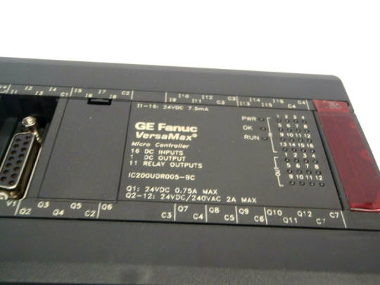
Battery (IC200ACC403) is required for data retention. Qty of 24, 14 point PLC, (8) 120VAC In, (6) Relay Out (2 at 10 amp & 4 at 2 amp), 120V/240VAC Power Supply Battery (IC200ACC403) is required for dtat retention. Battery (IC200ACC403) is required for long-term data retention & Real Time Clock Qty of 24, 23 point PLC, (13) 24VDC In, (1) 24VDC Out, (9) Relay Out, (2) Analog In & (1) Analog Out, 24VDC Power Supply. Battery (IC200ACC403) is required for data retention Tool box, 28 point, (IC200UDR005) 24VDC In/Relay Out, requires 120VAC Power, VersaMax SE (IC200SET001) with all software, cables (IC640VPS002)and manuals. Tool box, 23 point, (IC200UAL006) 24VDC In/Relay Out, requires 120VAC Power, VersaMax SE (IC200SET001) with all software, cables (IC640VPS002)and manuals. Tool box, 14 point, (IC200UDR001) 24VDC In/Relay Out, requires 120VAC Power, VersaMax SE (IC200SET001) with all software, cables (IC640VPS002)and manuals. Tool box, 10 point, (IC200NDR001) 24VDC In/Relay Out, requires 24VDC Power, VersaMax SE (IC200SET001) with all software, cables (IC640VPS002)and manuals. Includes (IC200UDR164) 24VDC In/Relay Out, AC Power Supply, (IC200USB001) RS-232 option board with (2) 0 -10VDC analog in with Proficy software, manuals and cables (IC646MPM101) Tool box, 28 point (IC200UDR005) 24VDCIn/Relay Out, 24 P/S, VersaMax DataPanel DP45 with Programming software and cables, (IC640VPS00, IC752DDZ000, IC200CBL555) Tool box, 23 point (IC200UAL006) 24VDCIn/Relay Out, 2 Analog In/1 Analog out, 24 P/S, VersaMax DataPanel DP45 with Programming software and cables, (IC640VPS00, IC752DDZ000, IC200CBL555) Tool box, 14 point (IC200UDR001) 24VDCIn/Relay Out, 24 P/S, VersaMax DataPanel DP45 with Programming software and cables, (IC640VPS00, IC752DDZ000, IC200CBL555) Tool box, 10 point (IC200NDR001) 24VDCIn/Relay Out, 24 P/S, VersaMax DataPanel DP45 with Programming software and cables, (IC640VPS00, IC752DDZ000, IC200CBL555) Includes (IC200UDD064) 24VDC In/24VDC Out, DC Power Supply,(IC200USB001) RS-232 option board with (2) 0 -10VDC analog in with Proficy software, manuals and cables (IC646MPM101) Tool box, 28 point, (IC200UDR005) DC In/Relay Out, AC Power Supply With software, manuals and cables (IC640VPS002) Tool box, 23 point, (IC200UAL006) DC In/Relay Out, 2 analog In, 1 analog out, AC Power Supply With software, manuals and cables (IC640VPS002)
Tool box, 14 point, (IC200UDR001) DC In/Relay Out, AC Power Supply With software, manuals and cables (IC640VPS002) Tool box, 10 point, (IC200NDR001) DC In/Relay Out, DC Power Supply With software, manuals and cables (IC640VPS002) I/O Expansion cable, 0.1 meter long (Qty 5)ġ0 point PLC, (6) 12VDC in, (4) Relay Out, (1) Analog Input (0-10VDC, 8 bit), 12VDC Power Supplyġ0 point PLC, (6) 24VDC In, (4) Relay Out, (1) Analog Input (0-10VDC, 8 bit), 24VDC Power Supplyġ0 point PLC, (6) 12VDC In, (4) 12VDC Out, 12VDC Power Supplyġ0 point (6) DC in, (4) DC Out, DC Power Supplyġ0 point (6) DC In, (4) Relay Out, DC Power Supplyġ0 point PLC, (6) 12VDC In, (4) Relay Out, 12VDC Power Supply Programming cable (RJ-45 to DB-9 pin) RS-232. RS-232 to RS-485 Converter requires IC200CBL500 or equivalent. Ge Fanuc Versamax Plc Programming Software Download Part No
0 notes
Text
Understanding Electrical Control Panels & Components

To achieve their diverse process goals, industrial equipment and machinery require specified functions and organised control. Within industrial equipment, these activities are carried out through electrical control panels.
Get insights from the best power panel manufacturer in Mohali.
An electrical control panel, in its most basic form, is a collection of electrical devices that use electrical power to manage the different mechanical operations of industrial equipment or machinery. An electrical control panel is divided into two parts: the panel structure and the electronic parts.
Components of the electrical control panel Panel Structure
An electrical control panel is made out of an enclosure and a back panel, comparable to a breaker box in a home or place of business.
Enclosures
The enclosure is a metal box that comes in many different of sizes and is often composed of aluminium or stainless steel. In most industrial applications, the size of the enclosure is determined by the number of doors (typically one or two). The enclosure will have a UL safety rating (often 508A), an IP rating, and/or a NEMA classification. These listings assist users in identifying properties such as:
Indoor/outdoor application
Waterproofing/resistance
Proofing against dust/solid contaminants
Rating for hazardous conditions
Rating for being explosion-safe
For simple identification and reference, these distinct classes should be printed on a metal plate and mounted to the enclosure. You must collaborate with a leading APFC panels manufacturer in Chandigarh and Mohali that deliver quality product and service.
Back Panel
A rear panel is a metal sheet that is positioned inside the enclosure and serves as structural support for DIN rail installation and wire duct. DIN metal rails have specified dimensions and are used to install electrical equipment. Wiring ducts help with wire routing and management while also reducing electrical noise between devices within the box.
Electronic Parts
Within an electrical panel enclosure, there are eight main sorts of electrical components that define and arrange the panel’s diverse functions. These elements are as follows:
Main circuit breaker
This is analogous to turning off the main electricity panel running into a house or workplace. In most industrial applications, main circuit breakers handle voltages ranging from 120V to 480V.
Surge Arresters
This part prevents overvoltage from harming the electrical components inside the panel caused by lightning strikes or utility power surges.
Transformers
Transformers may lower voltage to 120V for various components depending on the incoming voltage or step down the voltage to 24V in cases when the incoming power is 120V.
Terminal elements
These blocks aid in the organisation and distribution of wires from numerous sources to various electrical equipment.
Programmable Logic Controller (PLC)
This is effectively a CPU that is housed within the control panel. This device is the control panel’s brain, monitoring and controlling the numerous mechanical operations. It will incorporate numerous inputs and outputs to and from the industrial equipment’s automated operations.
For more technical details, consult an expert LT electrical panel manufacturer in Chandigarh.
Contactors and Relays
These on/off switches regulate automated functions based on PLC orders. Smaller relays are used to control things such as lighting and fans. Larger relays, known as contacts, regulate more sophisticated operations such as motors.
Network Switches
The control panel’s communication hub and network switches permit communication between the PLC and the numerous network compatible devices on the network.
Human-Machine Interface (HMI)
These components enable the operator to monitor or control certain functions of the machinery. Video displays, joysticks, buttons, switches, and keyboards are examples of common HMIs.
Electrical control panels are critical components of industrial automation. They enable businesses to design, plan, and accomplish production targets by providing higher-level monitoring and control of the many activities of production machines.
Balaji Power has long-standing experience and expertise in designing and building electrical control panels for businesses such as Food and beverages, Oil and natural gas, Pharmaceutical, Power generating and power distribution, Manufacturing, Handling fluids, Material Handling and more.
Balaji Power, a top electrical control panel manufacturer in Chandigarh offers new installations as well as updates to current systems For further information about electrical control panel solutions, please contact us.
Article Resource - https://balajipower.co/understanding-electrical-control-panels-components/
#APFC Panels#balajipower#APFC Panels in Chandigarh#APFC Panels in Mohali#APFC Panels Manufacturer in Chandigarh#Power Panel Manufacturer in Mohali#Power Panel Manufacturer in Chandigarh#LT electrical panel manufacturer in Mohali
0 notes