#Adjustable voltage regulator circuit
Explore tagged Tumblr posts
Visit Tumblr Blog
Explore Tumblr blogs with no restrictions, modern design and the best experience.
Last Seen Tumblr Blogs


Fun Fact
After the announcement of the deal with Yahoo!, there were 170K signatures of unhappy Tumblr users petitioning to prevent the sale in 2013.
Text
https://www.futureelectronics.com/p/semiconductors--analog--regulators-reference--linear-regulators/lm317d2t-tr-stmicroelectronics-3412715
Adjustable voltage regulator circuit, Fixed voltage regulator,
LM317 Series 1.2 V 1.5 A Positive Adjustable Voltage Regulator - D2PAK
#Regulators & References#Linear Regulators#LM317D2T-TR#STMicroelectronics#Adjustable voltage regulator circuit#Fixed voltage regulator#circuit#low dropout linear regulator#Linear voltage regulator types#AC voltage regulator
1 note
·
View note
Text
What is a Linear regulator, circuit, input voltage, adjustable linear regulator
NCP1117 Series 1 A 1.8 V Fixed Output LDO Positive Voltage Regulator - SOT-223
0 notes
Text
https://www.futureelectronics.com/p/semiconductors--analog--regulators-reference--linear-regulators/ncp5501dt33rkg-onsemi-4025789
Low dropout linear regulator, Battery charger, Linear voltage regulator circuit
NCP5501 Series 500 mA 3.3 V Fixed Output LDO Voltage Regulator - TO-253
#Regulators & References#Linear Regulators#NCP5501DT33RKG#onsemi#low dropout#Battery charger#Linear voltage regulator circuit#Adjustable#Output LDO Voltage Regulator#Voltage regulator#AC voltage regulator
1 note
·
View note
Text
https://www.futureelectronics.com/p/semiconductors--analog--regulators-reference--shunt-regulator/nud4700snt1g-onsemi-8877532
Low voltage shunt regulator, shunt voltage regulator, adjustable Regulator
NUD4700 Series 1 V 1.3 A Surface Mount LED Shunt - POWERMITE-2
#onsemi#NUD4700SNT1G#Regulators & References#Shunt Regulator#Low voltage#voltage regulator#what is shunt voltage regulator#Adjustable Precision Shunt Regulator#High voltage shunt regulator#shunt voltage regulator circuit#Voltage Reference
1 note
·
View note
Text
https://www.futureelectronics.com/p/semiconductors--analog--regulators-reference--linear-regulators/lm317d2t-tr-stmicroelectronics-3412715
Low dropout linear regulator, linear voltage regulator, AC voltage regulator,
LM317 Series 1.2 V 1.5 A Positive Adjustable Voltage Regulator - D2PAK
#Regulators & References#Linear Regulators#LM317D2T-TR#STMicroelectronics#Adjustable Voltage Regulator#circuit#Low dropout linear regulator#AC voltage regulator#Voltage divider network#High voltage regulators#Linear regulators power
1 note
·
View note
Text

Quick sketch for Piers’ bionic arm.

Design Features
•Aesthetics: Streamlined, ergonomic design with a minimalist look, often featuring a matte or metallic finish.
•Materials: Lightweight composites like carbon fiber and titanium, providing durability without sacrificing mobility.
•Color Options: Customizable colors or finishes, including options for skin-like textures or futuristic metallics.
Technology
•Actuation: Advanced motors and actuators that enable precise, fluid movement mimicking natural limb motion.
•Sensors: Integrated sensors (e.g., myoelectric sensors) to detect muscle signals for intuitive control and movement.
•Feedback Systems: Haptic feedback mechanisms to provide users with sensory information about grip strength and object texture.
Safety and Durability
•Water and Dust Resistance: High IP ratings to protect against environmental factors.
•Emergency Features: Manual override systems or fail-safes in case of technology malfunction.
Advanced Technological Interface
•Integrated Biosensors: Built-in biosensors that can analyze blood or interstitial fluid samples to measure viral load in real time.
•Data Analytics: Utilizes algorithms to process biosensor data, providing insights on viral dynamics and trends.
•Alerts and Notifications: Real-time alerts sent to the user or healthcare provider when viral load exceeds predetermined thresholds.
•Communication System: Integrated with a communicator on the wrist, the arm serves as a reliable device for maintaining contact with his team. This system includes encrypted channels for secure communication during high-stakes operations.
•Objective Management Display: The arm features a holographic display that provides a detailed version of the communicator’s data, allowing Piers to view mission objectives and tactical data in real-time. This feature minimizes the need for external devices and keeps critical information accessible.
Augmented Reality (AR) Compatibility
•Enhanced Visualization: The arm’s display projects augmented reality overlays, allowing Piers to see additional information, such as enemy positions, weapon stats, or tactical directions, directly in his line of sight.
•Environmental Scanning: The arm can analyze the surroundings for potential threats, detect biological or chemical hazards, and provide alerts for safer navigation through hostile environments.
Electricity Conduction and Control
•Energy Conduit Design: The bionic arm acts as a conductor for the constant electrical energy generated by Piers’ mutation. It includes specialized channels and circuits designed to manage this energy flow, allowing Piers to use his mutation’s electrical pulse without it spiraling out of control.
•Dielectric Structures: The arm’s design incorporates materials that mimic the dielectric properties of his mutated tissue, particularly in the finger joints and bones. These dielectric components help regulate and contain the high voltage his body produces, diffusing excess energy safely throughout the arm.
•Controlled Release Mechanism: To avoid overload, the arm features a controlled release system that allows Piers to release pulses of energy strategically, whether in combat or to alleviate the internal buildup. This system prevents the arm from overheating or sustaining damage from prolonged electrical activity.
Containment and Compression of the Mutation
•Compression Framework: The prosthetic was specially designed by UMBRELLA engineers to act as a containment “net” around his mutation. It includes a flexible, reinforced framework that compresses the mutated tissue, keeping it in check and preventing further growth or erratic shifts in form.
•Adaptive Pressure System: As the mutation strains against the arm, sensors detect any changes in size or energy output, triggering adaptive responses. The arm tightens or loosens as necessary to hold the mutation back, functioning almost like a high-tech brace that adjusts in real-time to maintain Piers’ arm in a stable form.
•Automatic Safety Lock: In the event of a significant spike in mutation activity or electrical output, the arm engages an emergency lock to keep the mutation from expanding. This feature is a safeguard against sudden bursts of energy that could cause the arm to revert to its mutated state.
Dependency and Risks of Removal
•Rapid Mutation Onset: Without the prosthetic in place, Piers’ arm begins to mutate almost immediately, returning to its original, unstable form. The electrical pulse that his body generates becomes unrestrained, emitting a continuous, breath-like rhythm that is both painful and dangerous, with energy leaking through protruding bones and exposed tissue.
•Uncontrollable Pulse: When uncontained, the electrical pulse from his mutation surges in intensity, lacking any natural “closure” or stopping point. This pulse causes rapid fluctuations in his vital signs and risks systemic overload, leading to loss of control over his mutation and putting him at severe physical risk.
Miscellaneous Details
•The arm has a unique serial code engraved on an inner plate, serving as an identifier for UMBRELLA technicians. This code also links to Piers’ personal health records, mutation data, and arm specifications for quick access during maintenance or in emergencies.
•Due to the intense electrical pulses generated by his mutation, the arm is equipped with an internal cooling system. Micro-fans and heat-dissipating channels prevent overheating during extended use, keeping the arm at a safe, comfortable temperature. If the arm overheats, an internal alarm alerts Piers to prevent any potential damage.
•The outer layer is treated with a UV-resistant coating to protect it from environmental damage and exposure. This ensures that prolonged exposure to sunlight or harsh conditions doesn’t wear down the arm’s exterior, making it more durable in diverse climates and situations.
•Designed for various operational environments, the arm is fully waterproof and corrosion-resistant. It functions normally underwater, which is crucial for aquatic missions or when exposed to rain, mud, or corrosive substances.
•The holographic display can be customized to show additional details, such as weather, GPS navigation, or tactical maps. Piers can also set personal preferences, like color schemes or alert tones, for a more intuitive user experience. This flexibility lets him prioritize the information he finds most critical during missions.
•The communicator has an onboard language translator, enabling Piers to communicate with individuals across different languages. The arm’s display shows translated text, and a subtle earpiece can even relay audio translations, making it easier for him to gather intel and negotiate in multilingual environments.
#𝐒𝐮𝐛𝐣𝐞𝐜𝐭 𝟏𝟑#𝐌𝐮𝐬𝐞; 𝐏𝐢𝐞𝐫𝐬 𝐍𝐢𝐯𝐚𝐧𝐬#I think I very severely fucked up my lefts and rights Ngl but oh well#resident evil#resident evil 6#piers nivans#long post
47 notes
·
View notes
Text
Covenants and other Provisions
Chapter 52
Something Blue
Rain came in thick sheets by dusk, drumming hard against the cabin’s corrugated roof—like fingers on a rusted tin drum, relentless and uneven. Each impact sent a hollow tremor down the walls, into the floorboards, and deeper still into the concrete veins of the lab.
Below, it felt like being submerged.
The hush was complete—so complete it dulled the passing of time itself. No rat wheel creaking. No bundled wires to dodge. No haphazard drifts of paper. Just current and heat and thought.
Fiddleford had called it for the night, muttering something about headaches and humidity and dinner that hadn’t agreed with him. But Ford had only been working for nine hours—nowhere near the threshold where exhaustion overtook obsession. Especially not with all the new space. The open floors, the cleaner shelves. The lingering adrenaline of adaptation.
He hovered over a circuit array, tweezers poised, shoulders hunched in concentration. The movements were infinitesimal—every adjustment a breath held steady, every connection soldered to silence. His glasses slid lower on the bridge of his nose and stayed there, forgotten.
Bill lingered inside the quiet with him—cool, coiled, and watchful. His awareness was braided with Ford’s, nested just beneath each thought, guiding every nerve.
Outside the lab, the world blurred. Just the storm—rain sheeting sideways across the clearing, the wind bending trees like fevered limbs, thunder growling at the horizon. Inside, only the ticking of the regulator. The slow, meditative exhale of machines at rest. Ford’s own breathing, matched perfectly to Bill’s—A small world, perfectly contained.
Until—
A crash—then several—split through the ceiling—and the moment broke all at once.
Glass shattered. Something heavy toppled. And somewhere in the mix—a voice. Loud. Sharp. Fiddleford.
Ford jerked. The tweezers pinged from his grip, gallium arsenide still clinging to their tips as they spiraled into shadow. But even before it struck the ground, Bill surged forward behind his ribs—a jolt of voltage and heat that shorted hesitation clean out of him.
Move, Sixer.
Ford’s chair hit the floor with a bang. He vaulted the bench, papers scattering in his wake, lab coat cracking like a sail behind him. His boots skidded on the concrete—caught, pushed off—every synapse charged with singular focus: Upstairs. Now.
The storm strobed across the kitchen—rain-slanted shadows, flashes of motion. The cabin trembled with it. Another thud. Another shout.
“—Fidds?”
Ford didn’t wait. He tore through the main room, the entryway lurching sideways for a breath before righting itself. Lightning cast the furniture in pale sheets.”
Deeper in: another crash. A full throated curse. Bill’s presence flared—hot now, almost snarling. “Careful. We don’t know what we’re walking into.”
Ford’s fingers flexed, instinct searching for the blaster that wasn’t there—still holstered on the lab rack, useless now. Too late.
His heart slammed against his ribs. His body surged forward anyway.
The hallway reeked of wet timber. Rain had soaked through somewhere, darkening the seams of the floorboards. Ford’s boots landed hard, slipping once, catching. The first door on the right—
It flung open, Ford stopped
Fiddleford was everywhere.
Drawers gaped from the sideboard like broken teeth, their contents flung in drifts across the floor—outdated manuals, crumpled blueprints, Polaroids curled in on themselves like dried leaves. A lamp lay shattered across the rug, jagged porcelain splayed like the debris of a small explosion. One of the chairs was on its back, a leg cracked clean off, splinters glinting in the dim light.
And Fiddleford—he stumbled from bookshelf to desk, not seeing where he was going, only reacting—knocking over a jar of pens, knocking over himself. His eyes were wild—unfocused, unfixed—caught mid-panic, too furious to freeze.
“Fid—whoa, hey.”
Ford raised both hands, palms open. He pitched his voice low, soothing, like approaching a shorted-out machine. “What’s going on?”
Fiddleford spun, clutching a fistful of paper he seemed to only now realize was in his hand—it looked like a letter. His chest heaved; each breath sounded like it was being pulled from under something heavy. And when he finally spoke, his voice scraped raw—half shout, half sob: “She’s leaving me.”
The words dropped like glass.
“She’s—” Fidds choked, shoved both hands through his hair, fingers knotting in the strands. He pulled, hard. “Emma Mae—she’s been—God, Ford, she’s been seein’ somebody else. Sleep in’ with some—some,” his arm swung, knocking a jar of spare change across the room. “—Prick from the hardware store!”
Fidds slammed the stack of papers down onto the desk. They scattered like frightened birds. Ford could only watch.
“Says she’s tired of it. Tired of me. Of my excuses…”
Ford stepped forward instinctively—but Fiddleford’s arm flew out, a finger pointed in Ford’s direction. Not a threat. A warning.
“You know what else she’s tired of?” he spat. His voice was splintered now, wobbling between rage and disbelief. “You,”
Ford’s brows furrowed. “Me?” he said incredulously.
“You.” Fiddleford repeated. He snatched a notebook from the desk, thrusting it toward Ford like evidence. “She says everything’s a you problem now. That everything changed when I came to work for the great Stanford Pines!”
The name caught on something in his throat, cracked against it. His hand braced on the desk. The other fisted uselessly at his side. “She wants full custody. The house—I’m leaving tonight.”
The air in Ford’s lungs felt like static. He reached forward—slowly, unsure where comfort might land without doing more damage. His hand hovered uselessly in the air between them.
“What about the contact?” he asked—fast and far too practical, the words out before he could soften them. “The project—you leaving now would put everything at risk—”
Fiddleford’s head snapped up.
And Ford recoiled his hand, stopping in his tracks.
“I don’t give a fuck, Ford. Okay?” Each syllable struck like a hammer. “That shit won’t fix my marriage.”
Fidds shoved past him, shoulder slamming hard into Ford’s, knocking him sideways a half-step. Ford caught the edge of the doorframe and turned, but the hallway already felt different—emptied.
“I have to go save my family.”
The storm outside had coiled into something monstrous—rain hammering the roof in frantic, arrhythmic fists. The gutters overflowed, releasing sluiced waterfalls that sheeted across the porch and wept from the beams. The windows rattled in their frames, their silver veins alive with each pulse of lightning.
Inside, the cabin was all motion.
Fiddleford tore through the rooms like a man caught in a house fire. He grabbed life in fistfuls—every drawer he yanked screamed on its runners; every cupboard slammed hard enough to leave the dishes ringing long after he’d moved on.
Ford hovered shortly behind, trying—still—to wedge sense between the cracks of rage. It was useless. Every word landed too late. Every attempt slid off the storm-slick surface of Fiddleford’s focus, unable to find purchase.
“Just—stay until morning,” Ford tried, following him to the door, voice swallowed even as he raised it. “You don’t have to drive in this—Fid, just wait—”
But Fiddleford was already moving into rain-laced wind, rushing past the threshold into the flickering wash of the porch light, then down the steps into the downpour. Ford followed—apologies and questions slipping loose, too many and too little to hold back what was happening.
“Fid!” he called out again, desperate now. “I need you—”
That stopped him. Just a few steps beyond the base of the steps, he paused—then he turned. Rain stippled his glasses. His jaw was set. His eyes were red—not just from the wind, not just from the cold, but he didn’t look away.
“I’m sorry, Ford,” he said quietly. “I’m not… I’m not like you.”
Lightning split the sky wide open, illuminating everything in a single, white frame.
Ford saw it all at once—the way the collar of Fiddleford’s coat flared awkwardly in the wind. The way the sleeves bunched at the elbows. The way he didn’t flinch at the cold. The way he didn’t look back again.
He hoisted his suitcase against one hip like dead weight. The Mustang loomed just beyond the fringe of the porch light, slick with runoff. He opened the door, climbed in, started the engine.
Thunder rolled overhead, long and low, and the rain surged colder, harder, washing across Ford’s shoulders in violent diagonals. The Mustang headlights flared—sharp, merciless—cutting through the downpour like teeth. The door slammed. The engine caught. Tires spun, mud churned.
The taillights bled red into the fog. Glowing like coals in a drowned world—bright, trembling, receding. The outlines blurred, then softened, then smudged. The trees closed in around them. And then—
Nothing.
Just the storm.
Ford stood frozen at the edge of the porch, one hand locked around the support post, knuckles bleached white.
Behind him, the cabin door hung ajar—gaping, crooked on its hinge, letting the storm spiral through the rooms Fiddleford had left in shambles. A mouth that couldn’t close. Couldn’t explain. Could only echo the absence it now contained.
And then—Bill stirred.
His voice surfaced like a ripple in still water—low, velvet-soft, amused. “Wow. Not even the melodrama of begging in the rain could stop him—that’s gotta sting,”
Ford didn’t move.
“Oh, if only,” Bill went on, just as softly, “there was someone’s arms you could fall into for comfort right now.”
The words landed like a tap on an open wound—casual, cutting, and achingly familiar, hanging in the flash of light as thunder rolled on.
—
Three days passed.
No word. No phone call. Not even a postmark from Tennessee—and in the vacancy Fiddleford left behind, time lost its shape.
Hours kneaded into one another, days stretching out in long, bruised smears across the calendar. The clock hands moved, but the meaning didn’t stick. The sun came and went like someone flicking a switch in another room.
Ford retreated into the lab with zeal. With something just shy of guilt and just past obsession. The kind of tunnel-vision you didn’t climb out of so much as absolve yourself through.
Bill was everywhere at once. A murmured suggestion, a pulse of approval, a bright needle of impatience. Together they burned through graphite, solder, and sleep, chasing coherence through circuits that glowed fox-fire green in the low light. Coffee cooled to sludge at Ford’s elbow; he drank anyway, accidently crunching the grit at the bottom of each cup before abandoning the mug wherever it landed—on blueprints, on notebooks, on shelves still scattered with remnants of Fidds’ organization.
When exhaustion finally pried the tweezers from Ford’s hand, Bill took him elsewhere. Into places not tethered to space or time—where they found themselves fluent in the language of curiosity and hunger.
And when Ford awoke—smiling and sated to the marrow—the answers came easy again.
Upstairs, the cabin began to forget itself.
Dirty dishes collected in the sink, stacking in careless layers, a geology of apathy. Coffee grounds formed constellations on the counter. A spoon lay just behind the grinder where it had fallen three mornings ago—now crusted into place like a fossil.
An oily hush that pooled in the corners, that wrapped around the places Fiddleford had once animated—his sighs, his banter, the scrape of his chair, the click of the space bar as he typed too loudly. At first Ford didn’t register it—there were too many voltages singing in his skull. Too many theorems to hunt.
But between those moments—when his soldering iron cooled or the paper ran out or the circuit didn’t blink the way it should, the silence would press against his eardrums. Loud. Dense. Like a question.
And Bill, always attuned, filled the gaps like incense.
But sometimes—just sometimes—on the edge of Ford’s consciousness, just before the lab dissolved into another impossible landscape, he could feel Bill listening too, waiting for an echo that refused to return.
On the fourth dawn, the rain had stopped.
The world outside lay washed clean, but the windows were still fogged with condensation, the air inside the cabin thick and sour. The back door stood propped open with a bootheel, letting damp air curl through the hallway.
Ford placed another mug beside the sink.
Porcelain clinked porcelain. A tower shifted. Several plates slid. Ford caught the stack before it would tip, steadied it, but didn’t bother washing a single one.
He stared at the mess.
At the quiet accusation.
And then turned away before the silence had a chance to ask something he wasn’t ready to answer, descending the stairs and vanishing back into the place where time had stopped tracking him.
On the fifth morning, Ford stood in the kitchen at first light. The air was thick—stale with overnight soldering and cigarette smoke, the faintest trace of something sweet gone to rot in the trash beside the sink.
The kettle hissed on the stove, its warped aluminum base stippled with rust. The coffee maker stopped working—go figure—and fixing those sorts of things was something Fidds usually did. Plus, Ford and Bill were teadering at the edge of another breakthrough after days of working at it. Samples of Shifty’s cells were proving useful in their pursuit of understanding cross dimensional chemistry—how biological molecules interact as they shift phase states. So, for now, he had to make his coffee the old fashioned way.
Steam coiled toward the ceiling in slow ribbons, catching the gray-pale light that filtered through the condensation-streaked windows. The bulb overhead buzzed faintly, flickering once, then held.
Ford moved by habit. He opened the cupboard with a practiced reach, expecting to find the same several mugs he rotated through—diner-grade things, stacked with lazy indifference. But the shelf was nearly bare now. Only a few remained, pushed far to the back—relics from when he’d first moved in—The kind of things that never got used, never rotated forward. Ghosts cast in ceramic.
With a short exhale, part sigh, part annoyance, he stretched up onto the balls of his feet, reaching into the shadowed shelf where unused things went to sleep.
His fingers found something heavy in the hand. Not the usual matte diner weight but something glazed. He drew it out.
The mug was pale blue. The glaze soft and cloudy, like morning sky over water. Across its side, in bold mid-century script, the souvenir lettering read: Atlantic City, 1962.
The paint had aged to a brittle spiderweb of cracks. Hairline crazing ran beneath the gloss, tiny fault lines mapping time. The handle bore a small dent—thumb-sized—where the clay had slumped slightly during firing—a moment in the making.
Ford’s own thumb landed in the groove without thinking. His breath hitched. A muscle fluttered beneath his right eye, small and involuntary.
The kettle hissed louder, but the kitchen had gone otherwise still.
He turned the mug slowly in his hand, letting the light catch across the sea-glass blue. A breath of memory stirred—he’d seen it before. It had been handed to him. And he had taken it, not because he wanted to, but because he didn’t want to refuse.
The kettle’s whistle scythed through the kitchen—shrill, blade-clean—but Ford just kept staring at the dent beneath his thumb.
The pale blue glaze seemed to pulse with its own slow rhythm, like blood behind skin. In the space of a blink, time thinned—and the present peeled back.
The overhead nicotine-yellow light struggled to illuminate the dinky apartment kitchen. Filbrick at the head of the kitchen table, shoulders hunched, eyes fixed—the same mug in his hands. Pale blue porcelain looked almost dainty cradled in those thick, gnarled fingers.
He tilted the cup to his lips, and above the rim, his gaze never wavered—deadlocked on the boy across the table. His son.
Outside, a lawnmower droned on the neighbor’s lawn. Inside: stillness. And the smell—Brut cologne, sharp and synthetic, clinging to Filbrick’s shirt collar, masking something meaner: The faint, acrid tang of gunpowder. Leftovers from whatever came with a “late night.”
Ford’s teenage hands stayed flat on the table, eyes pinned to his fingers—the smudges on the knuckles, watching the tremor, all while feeling the slow, smoldering pride in his father’s eyes.
The kettle screamed—Ford’s grip tightened around the mug in the here and now.
The scene fractured—A different room. Same man. Same eyes. Filbrick’s shadow looming over him as he lay on the living room carpet. His hand clamped to the back of Ford’s neck. His voice—a low snarl—serrated with something far darker than fury: “I’ll fucking kill you.”
The words still ricocheted in his skull, etched like lines on a plate.
And then—that flare. Bill lurching forward inside him—violent, reactive, razing the memory flat. The feeling was seizure-adjacent: teeth clamped, vision sparking.
The afterimage of Filbrick still lingered behind Ford’s eyelids—etched into the flash like a photographic ghost. The whistle kept screaming, a knife across his nerves. Water spilled onto the burner, hissing, snapping.
Ford’s chest seized. Once. Twice. His lungs clawed at the air, but every inhale dragged that same old stench—cheap cologne, gun-smoke, stale liquor on breath.
“Sixer?”
Ford’s lungs refused.
No warning. No negotiation. Just—lockdown.
Air stalled halfway down his throat, muscles seizing like a cranked vise. His chest strained against itself, ribs compressing, lungs fluttering uselessly like paper bags in a vacuum.
A high, electric whine surged in his ears. Not external—internal. Some private alarm bell only he could hear, bright and shrill as migraine light. His eyes fluttered. The mug in his hand blurred, doubled. His fingers went slack.
Crash.
Ceramic detonated on tile. Shards skittered under cabinets—but the sound didn’t land properly. It felt far away. Everything did. All noise collapsed inward until only his pulse remained—thudding, arrhythmic, deafening.
Ford staggered back. His palm slammed the wall, searching for something real. His shoulder hit next, then his hip—off-balance. His knees buckled but didn’t give. Another breath wouldn’t come.
His throat worked but drew nothing. A dry, stuttering wheeze. Every rib a locked gate.
“Ford.” Bill’s voice slid forward—low, deliberate. A steady pressure behind Ford’s eyes, like a hand on glass. “Breathe—easy does it.”
“I’m—I’m just windy,” Ford rasped. “Too much coffee or—fuck—”
His vision constricted. Peripheral detail drained away, the kitchen narrowing to a tunnel of warped light and scattered glass. The room tilted—floor rising at the corners like a capsizing raft. He clutched at his chest.
Bill’s tone sharpened. “Focus, IQ.”
“I can’t—” Ford gasped. His legs gave another warning tremor. Shards shifted underfoot with a sound like ice cracking. “I—can’t—”
“Ford, stop,” Bill said with a forced calm, tamping down his own rising static.
Ford began counting the erratic thuds: one-two-three-… a skipped beat that felt like a dropped elevator. Sweat prickled cold across his scalp. He drew a ragged sip of air, held it for a desperate second, let it shudder out. Again. And again. He looked down at the splintered mug, scattered memory in pieces, crunching under his feet like…like—
Snow.
Hard winter snow.
Dry and bladed. The kind of cold that bit. He felt it—through his jeans, through the floor—gritty frost rising through the seams of denim, gluing the fabric to his skin. His teeth clicked from the cold. And his knuckles ached.
Ford looked down.
His right hand was split and slick—raw, caked with half-frozen blood. His wrist throbbed with the dull ache of recent impact. The smell hit next—copper-heavy, hot and nauseating against the freeze. He tasted iron in his throat, sticky and metallic, bitter-sweet like nickels pressed to the back of his tongue.
Somewhere in the whiteout: a dull, wet thump, followed by the echo of his own ragged grunts—raspy and loud like an animal’s. Something terrible had happened. Something he did. Something they had done.
He tried to see it—but the second he reached toward detail, a black pane dropped over it, slick and final. Like tar poured over glass. It swallowed the image, deadened the sound. Bill surged forward in his mind—a flare: hot gold against polar dark—and shoved the pane harder, locking it into place.
Ford’s pulse spiked, sudden and brutal. He pressed both palms to his temples—hard enough to hurt.
“What did we do?” he choked out. His voice broke across the words, thin and scorched. “Bill—fuck—what did we do?”
But Ford’s shins still ached from the frost.
His hands came back down, palms up and open—trembling before him. He wiped them on his shirt, but no matter how many times he did, the blood wouldn’t wipe away.
Bill’s voice cracked through Ford’s skull—no velvet purr, no flippant drawl, only a sharp-edged command, raw and unvarnished, threaded with something dangerously close to fear.
“Ford. Come on—calm down. Stop.”
But the harder Bill pushed, the tighter everything locked. Ford’s lungs refused their function. His diaphragm jolted, stuttered, clenched. Each inhale rasped like torn paper—thin, useless, fraying at the edge of collapse.
The black pane—the one sealing off the snow, the blood, the truth—shimmered in his mind’s eye. A hairline crack spidered through its center and began to splinter. Behind it, bodies moved—but Bill refused.
“I said—stop!” Bill’s voice cracked like a whip.
A golden spike, clean and surgical, drove down Ford’s spine—white-hot and non-negotiable.
A full-body unspooling, slack and sudden.
Ford’s eyes rolled back, just a flash of white beneath his lids. His jaw went loose. His limbs fell open—he pitched sideways—but at the last second, one hand caught the counter’s edge reflexively.
And then—a shift.
A shiver beneath the skin.
His body lifted—not of his own volition but like something was pulling upward from inside. His spine straightened in jerks, vertebrae lining one by one. His shoulders rolled back. His neck tipped, head lolling as if testing the fit of its weight.
Bill exhaled through Ford’s mouth. A slow, clinical rhythm, coaxing breath back into order. Slowing the heart. Resetting the machine. “That’s it, Six.” came Bill’s voice, “Just settle down,”
Ford’s head tilted left, then right, jaw cracking faintly. One palm flexed on the counter. The other hovered just above the floor, fingers curling, uncurling—testing the tension, the resistance.
“You’re alright, my love.” Bill muttered, settling deeper into the borrowed shape like slipping into an old coat. “I’ve got you.”
[Previous Chapter][Next Chapter]
[Read Entire Work Here]
[Spotify Playlist!]
#hey bill that wasn’t very cool of you#one might even say#toxic#billford#bill cipher#stanford pines#gravity falls#covenants and other provisions#ford pines#billford fanfic#my writing#fiddleford mcgucket
9 notes
·
View notes
Note
tell me everything about AC to DC filters Right Now
:0
Dear god.
OK I have to make some assumptions or else this is going to get really long. I am going to assume that you already know what AC and DC are. I am going to assume that you took (and passed) geometry, so a sine wave and it's variations are familiar to you. I am also going to assume that you also know the difference between voltage, current, and resistance.
So, what are AC to DC, why do we care about that? Well, the electricity coming out of the wall is AC, but in order to, lets say, charge your laptop battery, you need DC. In fact, if you look at a laptop charger, you'll see The Brick. The thick rectangle that gets hot when charging the laptop.
THAT'S THE AC TO DC CONVERTER
I just called it converter instead of filter. Why? Because filters technically only remove a 'ripple' from DC current, so a current that's almost DC but not quite. If you are making the entire jump from AC to DC, then that's called a converter.
Now here's where things get fucked.

These are all of the parts after the plug. The load is your laptop, the regulator is your filter.
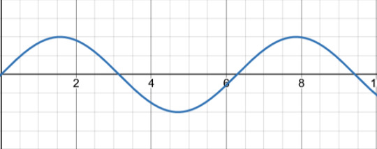
Let's say that this is your AC signal (this graph showing the voltage over time). Now, the first thing this passes through is the transformer, which only adjusts the voltage to the correct level. Some devices need it higher, some lower. Let's say that this transformer is a step up transformer, because it made the signal bigger.

The next step is the rectifier. Now, traditionally this part is taught in stages in order to show it's affect on the signal. I'm going to speed run that. I will assume that you're familiar with what a diode is. If you aren't, just know that it only allows current to flow in one direction. So, anything going backwards will be removed. Picture a one way valve.
So, if we were to send this signal through one diode, then that would leave us with
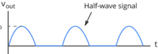
just the positive half! That's why this setup is called a Half-wave rectifier.
But what if we were to use two diodes. As in, fill in the blank spot that the negative half left with another positive bump. That would give us

This lovely thing! Which is great, but it requires another AC signal that is 180 degrees off from the original one in order to exist. Which, transformers exist which can provide that, but it's not cost effective. So, that leaves us with the most common setup, the Bridge Rectifier.
I've been skipping the circuit diagram so far, but now it's important.
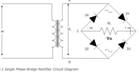
THIS thing is a bridge rectifier connected to the transformer (yes that's what transformers look like according to circuit diagram shorthand). Now, I am American, and for some reason American electricians use that up and down sharp thing in the middle of the diamond to indicate a resistor. Europe uses a rectangle. Again, I am going to assume that you know what a resistor does.
Those four black triangles with lines? Those are diodes. The line across the tip of the triangle indicates what direction they are allowing current to flow into. Now picture you were a positive signal flowing in through point A into the bridge. There's a split in the circuit, but one way (diode D4) is blocked, so you have to go across diode D1. Now you're at the edge of the diamond, once again two ways you can go. You head towards diode D2, because diode D3 won't let you through. What that looks like is this
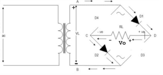
What about the other direction? Well that looks like
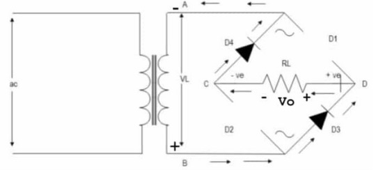
Notice that the edges of the diamond are called out? Points C and D. That's the money makers. You see, if you plug into point D as your positive and C as your negative, you get a full wave signal! (so sorry for not going fully in depth on why that works just trust me it's a bit of a mess and should really be taught with the actual circuit in front of you, not across the internet like this)
A full wave signal is completely positive, but it's not exactly DC yet. That's where smoothing comes in. This is done with a capacitor!

The capacitor is charged up and then slowly releases it's charge. But before it can completely discharge, it gets recharged by the next wave. Quick review, a capacitor is like a battery where it can be charged up, but unlike a battery which holds charge with chemistry, capacitors hold charge with physics. They can still wear out, but not nearly as quickly as a battery.
What does that red line look like? Well, almost like a straight line, except it has RIPPLES! That's right, we're finally back to the filter! Or the regulator as the diagram calls it. Means the same thing.
Sometimes, this step is skipped. If the device getting signal isn't too sensitive or it's just cheep, then the electricity stays bouncy. Some devices really care about any fluxuation in the signal, in which case they get a big expensive filter.
Unfortunately, the inner bits of a filter are many, so I won't be going into all of that. But you want me to go into that, so I will show a circuit diagram.

This is a diagram of the ADP1612
This website has a downloadable version of the spec sheet!
But that's a level of detail that you usually only get into if you are planning on building a circuit. The day that you're flipping through spec sheets in order to check compatibility is when you've really become an engineer.
So that's how you go from AC into DC. Yes, I just spent an hour typing this all out. I like electricity a lot.
Here's a GREAT video that goes over all of this but the guy actually has a circuit and an ossiliscope in front of him to show the signal.
#electricity#electronic#electrical engineers#physics#AC to DC rectifier#electrical engineering#mmm electricity for power#ask#literally several college classes worth of info that I am skipping in this#ough my circuit bits#I chose the perfect degree I am built for this shit
10 notes
·
View notes
Text
How do I solve the BS4 headlight problem in the Royal Enfield bullet?
Here's a comprehensive guide to solving the BS4 headlight issues in your Royal Enfield Bullet, combining technical fixes and practical solutions:
Diagnosis & Solutions Upgrade to LED/Halogen Hybrid Bulbs
The stock 35W halogen bulbs in BS4 Bullets often provide insufficient illumination. Consider:
Philips X-tremeVision 55W Halogen (direct fit, 150% brighter)
LED Conversion Kits like those from TradeChina.com with 6000K color temperature for better road coverage
Caution: Ensure LED conversions include anti-flicker resistors to prevent CAN bus errors Voltage Regulation Check
BS4 models suffer from unstable alternator output (5.5-14.5V fluctuations):
Test voltage at headlight connector using multimeter
Install voltage stabilizer (e.g., Roots VST-300) if readings exceed 14.2V
Replace corroded bullet connectors with waterproof Deutsch DT connectors Beam Alignment Adjustment
Misaligned beams cause poor illumination and glare:
Park 25ft from wall on level ground
Use 8mm hex key to adjust vertical screws on headlight nacelle
Ideal pattern: Cutoff line at 2.1" below headlight center height Housing & Reflector Maintenance
Cloudy reflectors reduce output by 40%:
Remove headlight assembly (4x 10mm bolts)
Polish reflector with 3M Headlight Restoration Kit
Apply UV-resistant clear coat to prevent yellowing Enhanced Cooling Mods
Bullet's sealed housing causes bulb overheating:
Drill 4x 5mm ventilation holes in lower housing
Install silicone-insulated wiring (reduces resistance heat)
Add heat sink kits for LED conversions
Preventive Measures Apply dielectric grease to all electrical contacts
Install TOPBIRD metal headlight ring (₹359) for vibration protection
Carry spare H4 bulbs in waterproof case under seat
Perform monthly voltage checks during chain lubrication
When to Consider Full Replacement If issues persist, upgrade to: Royal Enfield Classic 650 Twin Headlight Assembly (direct fit with modified brackets)
H4 Projector Retrofit Kit (with halo DRLs) - requires 12V relay harness
Cost breakdown: Solution Estimated Cost (₹) Labor Time LED Conversion 1,800-3,500 45 mins Voltage Stabilizer 1,200 30 mins Full Projector Retrofit 8,500 3 hrs
For persistent electrical gremlins, consult authorized service centers to check ECU lighting circuit outputs . Most BS4 headlight issues stem from voltage irregularities rather than component failures.

#led lights#car lights#led car light#youtube#led auto light#led headlights#led light#led headlight bulbs#ledlighting#young artist#car culture#cars#race cars#classic cars#car#cartoon#suv#porsche#truck#supercar#automobile#carlos sainz#headlight bulb#headlamps#build a headmate#headlamp#headlight#aftermarket new lamp#lamp#car lamp
5 notes
·
View notes
Text
Understanding Circuit Board Electronic Components: A Comprehensive Guide
In today's digital world, electronic devices have become an essential part of our daily lives. But what makes these devices tick? At the heart of every electronic device lies a circuit board—a masterpiece of tiny electronic components working together to perform complex tasks. In this article, we’ll dive deep into the fascinating world of circuit board electronic components, exploring each element’s role and how they contribute to the overall functionality of the device.
What is a Circuit Board?
A circuit board, often referred to as a PCB (Printed Circuit Board), is a flat board used to mechanically support and electrically connect various electronic components. These components work in unison to perform a specific task. Think of the circuit board as the skeleton and nervous system of an electronic device—it holds everything together and allows communication between parts.
Types of Circuit Boards
Single-sided PCB: Has one layer of conducting material.
Double-sided PCB: Contains two layers for components and connections.
Multi-layer PCB: Complex boards with multiple layers for advanced applications.
The Role of Electronic Components on a Circuit Board
Every electronic device you interact with is powered by a carefully designed circuit board filled with various components. These components might be tiny, but each one has a critical role in the operation of the device. Here's a breakdown of the most important electronic components you’ll find on a typical circuit board.
1. Resistors
Resistors are fundamental components that control the flow of electrical current. They resist the flow of electrons, hence the name "resistor." Their primary function is to reduce current flow, adjust signal levels, and divide voltages in a circuit. Without resistors, circuits would allow too much current to flow, potentially damaging other components.
Types of Resistors
Fixed resistors: Have a set resistance value.
Variable resistors: Allow adjustment of the resistance.
2. Capacitors
Capacitors store and release electrical energy in a circuit. They are often compared to small rechargeable batteries that quickly charge and discharge. Capacitors help smooth out fluctuations in voltage, filter noise, and store energy for future use.
Common Uses of Capacitors
Energy storage
Signal filtering
Voltage stabilization
3. Inductors
Inductors are components that store energy in a magnetic field when electrical current flows through them. They resist changes in current and are typically used in circuits to filter signals, manage power, and store energy.
Applications of Inductors
Power supplies
Radio frequency circuits
Noise suppression in circuits
4. Diodes
A diode is like a one-way valve for electricity, allowing current to flow in only one direction. They are vital in circuits to prevent reverse currents, which can damage components.
Types of Diodes
Light-emitting diodes (LEDs): Produce light when current flows through.
Zener diodes: Regulate voltage within a circuit.
5. Transistors
The transistor is a versatile component used to amplify or switch electronic signals. In essence, transistors are like tiny switches that turn signals on and off rapidly, making them essential in modern electronics.
Types of Transistors
NPN transistors: Allow current flow when a small voltage is applied to the base.
PNP transistors: Conduct when the base is negatively charged.
How Circuit Board Components Work Together
In a circuit, each component has a specific role, and together they form a cohesive system. For example:
Capacitors and resistors may work together to filter signals or smooth out voltage fluctuations.
Transistors and diodes ensure that signals are amplified or directed properly.
Integrated circuits handle the complex tasks, processing data, and controlling the overall system.
Choosing the Right Components for Your Circuit Board
When designing or repairing a circuit board, choosing the correct components is crucial. Some factors to consider include:
Voltage requirements
Power consumption
Signal type and frequency
Physical size and compatibility
Conclusion
Circuit boards are an integral part of any electronic device. The various components on the board each play a specific role in ensuring the device functions as intended. Understanding these components, from resistors to integrated circuits, is essential for anyone working with electronics, whether you're designing a new system or troubleshooting an existing one.
2 notes
·
View notes
Text
Electronics Components and Uses:
Here is a list of common electronics components and their uses:
Resistor:
Use: Limits or controls the flow of electric current in a circuit.
Capacitor:
Use: Stores and releases electrical energy; used for filtering, timing, and coupling in circuits.
Inductor:
Use: Stores energy in a magnetic field when current flows through it; used in filters, transformers, and oscillators.
Diode:
Use: Allows current to flow in one direction only; used for rectification, signal demodulation, and protection.
Transistor:
Use: Amplifies and switches electronic signals; fundamental building block of electronic circuits.
Integrated Circuit (IC):
Use: Contains multiple electronic components (transistors, resistors, capacitors) on a single chip; used for various functions like amplification, processing, and control.
Resistor Network:
Use: A combination of resistors in a single package; used in applications where multiple resistors are needed.
Potentiometer:
Use: Variable resistor that can be adjusted to control voltage in a circuit; used for volume controls, dimmer switches, etc.
Varistor:
Use: Protects electronic circuits from excessive voltage by acting as a voltage-dependent resistor.
Light-Emitting Diode (LED):
Use: Emits light when current flows through it; used for indicator lights, displays, and lighting.
Photodiode:
Use: Converts light into an electric current; used in light sensors and communication systems.
Zener Diode:
Use: Acts as a voltage regulator by maintaining a constant voltage across its terminals.
Crystal Oscillator:
Use: Generates a stable and precise frequency; used in clocks, microcontrollers, and communication devices.
Transformer:
Use: Transfers electrical energy between two or more coils through electromagnetic induction; used for voltage regulation and power distribution.
Capacitive Touch Sensor:
Use: Detects touch or proximity by changes in capacitance; used in touchscreens and proximity sensing applications.
Voltage Regulator:
Use: Maintains a constant output voltage regardless of changes in input voltage or load; used for stable power supply.
Relay:
Use: Electromagnetic switch that controls the flow of current in a circuit; used for remote switching and automation.
Fuse:
Use: Protects electronic circuits by breaking the circuit when current exceeds a certain value; prevents damage from overcurrent.
Thermistor:
Use: Resistor whose resistance changes with temperature; used for temperature sensing and compensation.
Microcontroller/Microprocessor:
Use: Processes and controls electronic signals; the brain of many electronic devices and systems.
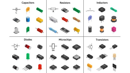
fig:google-electronics

fig:google-electronics
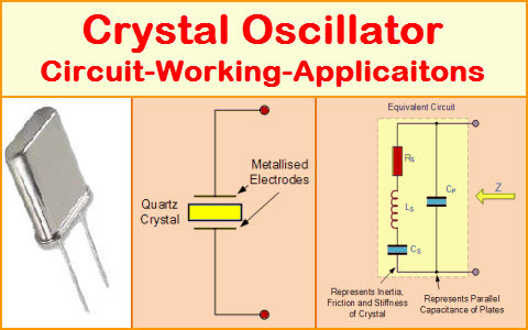
fig:Crystal-Oscillator
This list covers some of the basic electronic components, and there are many more specialized components used for specific applications within the field of electronics.
#electronic#electricity#electric vehicles#electric cars#engineering#semiconductors#wireless#cables#electronics#smartphone#hardware
4 notes
·
View notes
Text
Empowering Smart Automation with Electric Components & Precision Encoders
Where Electrical Intelligence Meets Motion Accuracy
In today’s advanced manufacturing landscape, smart automation depends on components that offer both electrical efficiency and motion precision. At Dropship Automation Solutions, we deliver industrial-grade parts that form the backbone of this transformation. This edition highlights two critical heroes in modern automation—Electric Components and Encoders—that together help build intelligent, responsive systems.
From powering equipment to tracking micro-movements, these technologies ensure your operations are not only reliable but also finely tuned to every demand.
1. Electric Components: The Power Behind Automation
🔌 What Are They? Electric components such as contactors, relays, and circuit breakers regulate, protect, and distribute electricity in automated systems. These parts ensure machines receive consistent, safe power for continuous operation.
🔧 Types & Use Cases
Types: Relays, Contactors, Circuit Breakers, Power Supplies
Applications: Control panels, industrial switchgear, automation cabinets
Benefits: System protection, voltage regulation, electrical safety
⚙️ Why They Matter An unstable power supply can disrupt even the most advanced automation. These components act as the electrical guardians—regulating flow, preventing overloads, and enabling safe startups and shutdowns. Without them, precision automation wouldn't be possible.
2. Encoders: Precision in Every Rotation
🎯 What Do Encoders Do? Encoders convert motion into digital signals, enabling automation systems to track position, direction, and speed. They're essential in environments where accuracy and control are paramount.
🔧 Types & Applications
Types: Rotary Encoders, Linear Encoders, Incremental, Absolute
Applications: CNC machines, robotics, conveyor feedback, lift systems
Benefits: High-precision control, real-time feedback, error minimization
📏 Why Encoders Matter In tasks requiring exact positioning—like aligning robotic arms or regulating conveyor speeds—encoders deliver the real-time data necessary for flawless operation. They bridge the gap between motion and intelligence.
🔄 The Perfect Pair: Power Meets Precision
Visualize a smart system where:
A relay ensures power is safely delivered to an automated lift
An encoder tracks every movement, adjusting elevation to the exact millimeter
This synergy between electrical reliability and positional accuracy drives performance, cuts downtime, and boosts production confidence.
💬 Final Thought: Building Smarter, Safer Systems
With intelligent electric components and high-resolution encoders, automation isn’t just faster—it’s smarter. At Dropship Automation Solutions, we offer more than parts—we provide the building blocks of innovation.
🛒 Explore our advanced electric components and encoders today. 📞 Call: +1 (234) 288-1755 📧 Email: [email protected] 📍 Visit Us: 1440 W. Taylor St #2555, Chicago, IL 60607
0 notes
Text
Understanding Voltage Monitoring Devices: Essential Tools for Power Reliability
interconnected and electronically driven world, maintaining a stable and reliable power supply is not just a technical preference—it’s a necessity. From industrial machinery and data centers to residential complexes and smart appliances, all electrical systems depend on consistent voltage levels to function safely and efficiently. When voltage fluctuates outside acceptable limits, it can cause equipment damage, data loss, safety hazards, and costly downtime. That’s where voltage monitoring devices come into play. These compact yet powerful tools are designed to continuously measure, record, and alert users to voltage anomalies in electrical systems. In this blog, we’ll explore how voltage monitoring devices work, why they’re essential, and how to choose the right one for your application.
What Are Voltage Monitoring Devices?
Voltage monitoring devices (also known as voltage monitors or voltage sensors) are electronic instruments that track voltage levels in real-time within electrical systems. Their primary function is to detect conditions such as:
Overvoltage
Undervoltage
Phase loss or imbalance
Frequency deviations
Voltage transients and sags
When voltage falls outside preset thresholds, these devices can trigger alarms, disconnect sensitive equipment, or activate protective circuits, depending on the system configuration.
Why Voltage Monitoring Is Crucial
1. Protects Equipment and Infrastructure
Voltage spikes or drops can severely damage motors, computers, power supplies, and control systems. Monitoring helps prevent premature wear and catastrophic failure.
2. Ensures Operational Reliability
Voltage anomalies can cause malfunctioning of automation systems, production halts, or corrupted data in IT infrastructure. Voltage monitoring maintains the stability of critical operations.
3. Improves Energy Quality and Efficiency
By identifying voltage fluctuations and imbalances, facility managers can diagnose inefficiencies and correct power distribution issues, reducing energy waste and enhancing performance.
4. Supports Preventive Maintenance
Real-time data and historical logs from voltage monitors can be used to schedule maintenance proactively, preventing unplanned outages and extending equipment lifespan.
5. Helps Meet Regulatory Standards
Industries like healthcare, manufacturing, and telecommunications are subject to power quality standards. Voltage monitors help document compliance with these regulations.
Key Features of Voltage Monitoring Devices
When selecting a voltage monitoring device, consider the following features:
Input voltage range: Ensure compatibility with your system (e.g., 120V, 240V, 480V, or custom ranges)
Single-phase or three-phase monitoring: Depending on your application
Adjustable thresholds: Customizable over/undervoltage limits
Digital display or remote communication: For local or networked visibility
Relay output: Enables automatic disconnection or alarm triggering
Data logging capabilities: For power quality analysis and reporting
DIN rail mounting or panel integration: For flexible installation
Common Applications
Industrial Automation: Protect PLCs, drives, and motors from voltage fluctuations
Renewable Energy Systems: Monitor inverter output and grid interaction
Commercial Buildings: Ensure stability for HVAC, elevators, and lighting systems
Telecom and IT Infrastructure: Prevent voltage-related data loss or equipment failure
Healthcare Facilities: Maintain consistent power to life-saving equipment
Utility Substations: Monitor and balance power distribution networks
Types of Voltage Monitoring Devices
Analog Voltage Monitors: Simple devices with fixed thresholds; suitable for basic applications
Digital Voltage Monitors: Feature precise settings, displays, and programmable logic
Multi-function Monitors: Combine voltage, current, frequency, and phase monitoring in one unit
Wireless and IoT-Enabled Monitors: Offer remote access, cloud logging, and integration with smart grids
Final Thoughts
In any electrical system, voltage stability is the backbone of reliability. Voltage monitoring devices offer a proactive and affordable solution for detecting and addressing power issues before they escalate into serious problems. By integrating these tools into your facility or infrastructure, you gain peace of mind, enhance safety, and ensure uninterrupted performance of your critical systems. Whether you're powering a factory floor or safeguarding sensitive servers, voltage monitoring isn't just good practice—it’s essential protection.
0 notes
Text
How to install car wheel lights?

1. Preparations
a. Confirm the hub light type
- Magnetic/Adhesive: Attaches or sticks directly to the surface of the wheel without removing the tire (suitable for temporary use).
- Embedded: The tires need to be removed and the light bar embedded in the inside of the hub (more stable, but complicated to install).
- Orifle type: Powered by a valve, it is simple to install but may be less bright.
b. Tools and materials
- Wheel light kit (including strip, controller, wiring harness, etc.)
- Screwdrivers, wrenches, crowbars, 3M glue
- Cable ties, electrical tapes, insulating tapes
- Jacks (if the tires need to be removed)

2. The installation steps
Solution 1: Magnetic/Adhesive Hub Lights (Easy Installation)
a. Clean the hub
- Wipe the surface of the hub with alcohol to make sure there is no oil and dust so that it can be firmly attached or adsorbed.
b. Fix the light strip
- Attach the light strip along the inside or outside of the hub and press to make sure it sticks firmly (if it is magnetic, it is directly attached to the metal hub).
c. Cable routing
- Hide the power cord along the inside of the suspension or wheel arch and secure it with a cable tie to avoid contact with moving parts.
d. Connect the power supply
- Usually connected to a 12V cigarette lighter or battery, make sure that the circuit is waterproof (a fuse can be installed).


Solution 2: Recessed Wheel Lights (Professional Installation)
a. Remove the tires
- Lift the vehicle with a jack and remove the tires to expose the inside of the hub.
b. Install the strip light
- Insert the LED light strip into the inner groove of the wheel hub (some models need to be perforated) and fix it with 3M glue or screws.
c. Wiring & Controller
- Thread from the hub to the chassis and connect to the controller (waterproofing required).
- The controller can be installed in the engine compartment or in the car, and the power supply is connected to the battery (the positive and negative poles need to be correct).
d. Test & Reset
- Test the lights before putting the tires back on to make sure the wiring harness is not pulled when the tires are turning.


3. Precautions
a. Security
- Avoid lights that interfere with the driver's vision or others (some countries have regulatory restrictions on the color/brightness of wheel lights).
- Make sure the line is away from hot or moving parts such as brake discs, suspensions, etc.
b. Waterproof and dustproof
- Use waterproof glue to seal wiring, especially areas on the inside of the hub that are prone to splashing.
c. Power supply mode
- It is recommended to connect to the ACC power supply (the light will turn on after the vehicle starts) to avoid battery power loss.
d. Debugging
- Some hub lights are controlled by APP, and the light mode (such as breathing, flashing, etc.) needs to be adjusted synchronously.
4. Frequently Asked Questions
- The light is not on: Check whether the fuse and wiring are loose and whether the power supply is energized.
- Unstable light: It may be that the voltage is unstable or the contact is poor, it is recommended to install a voltage regulator.
- Falling off problem: The adhesive type is easy to fall off at high temperatures, so it can be fixed with screws instead.
If you are not familiar with the operation of the circuit, it is recommended to install it in a professional modification shop to avoid damaging the vehicle circuit or affecting driving safety.
0 notes
Text
what do emergency lighting circuits often use
Emergency lighting circuits are critical components in modern buildings, ensuring safety during power outages or emergencies. These systems are designed to provide illumination automatically when the primary power supply fails, guiding occupants to safety exits and minimizing panic. The design and implementation of emergency lighting circuits rely on specific technologies and components to meet regulatory standards and operational requirements.
Power Supply Sources
Emergency lighting circuits typically utilize multiple power supply sources to ensure reliability. The most common configurations include:
Battery-Backed Systems: Integrated batteries within emergency lights or centralized battery banks are widely used. These systems charge during normal operation and activate automatically when power is lost. Modern LED emergency lights often use 6V or 12V rechargeable batteries, with charging circuits designed to prevent overcharging and extend battery life.
Generator Systems: For larger facilities, diesel generators or gas-powered units provide backup power. These systems are slower to activate (typically 10–30 seconds) but can sustain lighting for extended periods.
EPS (Emergency Power Supply) Systems: Specialized EPS units, which convert stored energy (e.g., from batteries) into AC power, are increasingly popular. These systems offer faster switching times (as low as 4ms for critical applications like tunnels) and support various load types, including fluorescent and LED lights.
Control Mechanisms
Emergency lighting circuits employ diverse control strategies to balance efficiency and safety:
Automatic Activation: Most systems use relays or solid-state switches to detect power loss and switch to emergency mode. For example, a relay might disconnect the main power supply and connect the battery backup when voltage drops below a threshold.
Centralized Control Systems: In large buildings, emergency lighting is often integrated into building management systems (BMS). These systems allow remote monitoring, testing, and control of individual fixtures via networked communication protocols (e.g., DALI, KNX).
Manual Overrides: Some circuits include manual switches for testing or temporary adjustments. However, these are typically restricted to authorized personnel to prevent misuse.
Lighting Technologies
The choice of lighting technology significantly impacts circuit design:
LED Lighting: Due to their low power consumption, long lifespan, and instant-on capability, LEDs dominate modern emergency lighting. Circuits for LED emergency lights often include constant-current drivers to ensure stable brightness and efficiency.
Fluorescent Lamps: Though less common today, fluorescent tubes are still used in some legacy systems. These require ballasts and may have slower start-up times, making them less suitable for critical applications.
Hybrid Systems: Some circuits combine LEDs with traditional lamps to balance cost and performance. For example, LEDs might provide immediate illumination, while fluorescent lamps activate after a delay.
Wiring and Safety Standards
Emergency lighting circuits must adhere to strict safety regulations:
Separate Circuits: Emergency lighting is typically wired on dedicated circuits to prevent interference from non-essential loads. These circuits are often protected by circuit breakers with lower trip ratings to ensure continuity during overloads.
Cable Specifications: Fire-resistant cables (e.g., mineral-insulated cables) are mandatory in many jurisdictions to maintain functionality during fires. For instance, the UK’s BS 5266 standard requires emergency lighting circuits to use cables rated for at least 30 minutes of fire resistance.
Grounding and Protection: Circuits include grounding conductors and surge protection devices to safeguard against electrical faults and lightning strikes.
Testing and Maintenance
Regular testing is essential to ensure reliability:
Self-Testing Systems: Advanced emergency lights include built-in test routines that verify battery health, lamp functionality, and charge status. These systems log test results for compliance reporting.
Manual Inspections: Quarterly or annual inspections by qualified electricians are standard. These checks include visual inspections, load testing, and documentation of maintenance activities.
Conclusion
Emergency lighting circuits are sophisticated systems that integrate power supplies, control mechanisms, lighting technologies, and safety standards to ensure reliability during crises. The evolution from traditional fluorescent lamps to energy-efficient LEDs, coupled with advancements in battery technology and centralized control systems, has significantly improved their performance. As building codes evolve, the demand for smarter, more resilient emergency lighting solutions will continue to grow. By prioritizing robust design, regular maintenance, and compliance with international standards, emergency lighting circuits remain a cornerstone of building safety, ensuring occupants can navigate safely in the darkest of times.
0 notes
Text
How Do Power, Motor & Robotics Development Tools Drive Innovation in Automation?

Introduction to Modern Development Ecosystems
As the era of intelligent machines, automation, and smart manufacturing continues to advance, Power, Motor & Robotics Development Tools have emerged as essential components in transforming ideas into functioning prototypes and commercial solutions. These tools serve as the backbone for developing precise and reliable control systems used in a wide variety of sectors—from industrial robotics to electric mobility.
With the increasing integration of microcontrollers, sensors, thermal management components, and electronic controllers, development tools offer a modular and practical approach to building sophisticated electronic and electromechanical systems.
What Are Power, Motor & Robotics Development Tools?
Power, Motor & Robotics Development Tools consist of hardware kits, interface boards, and control modules designed to help developers and engineers test, prototype, and deploy automated systems with precision and speed. These tools make it possible to manage current, voltage, mechanical motion, and real-time decision-making in a structured and scalable manner.
By combining essential components such as capacitors, fuses, grips, cables, connectors, and switches, these kits simplify complex engineering challenges, allowing smooth integration with controllers, microprocessors, and sensors.
Exploring the Primary Toolsets in the Field
Power Management Development Tools
Efficient energy management is crucial for ensuring stability and performance in any robotic or motor-driven system.
Development boards supporting AC/DC and DC/DC conversion
Voltage regulators and surge protection circuits for safe energy flow
Thermal sensors and oils to maintain system temperature
Battery management ICs to control charge-discharge cycles
High-efficiency transformers and current monitors
Motor Control Development Tools
Motor control kits are built to manage torque, direction, and speed across a range of motor types.
H-bridge motor drivers for bidirectional motor control
Stepper motor controllers with high-precision movement
Brushless DC motor driver modules with thermal protection
Feedback systems using encoders and optical sensors
PWM-based modules for real-time torque adjustment
Robotics Development Tools
Robotics kits merge both mechanical and electronic domains to simulate and deploy automation.
Preassembled robotic arm platforms with programmable joints
Sensor integration boards for object detection, motion sensing, and environmental monitoring
Wireless modules for IoT connectivity using BLE, Wi-Fi, or RF
Microcontroller development platforms for logic execution
Mounting hardware and cable grips for secure installations
Benefits of Using Professional Development Tools
Advanced development kits offer more than just experimentation—they serve as stepping stones to commercial production. These tools minimize development time and maximize productivity.
Enhance system performance with modular plug-and-play designs
Enable easy integration with laptops, diagnostic tools, and controllers
Reduce design errors through pre-tested circuitry and embedded protection
Facilitate rapid software and firmware updates with compatible microcontrollers
Support debugging with LED indicators, thermal pads, and status feedback
Key Applications Across Industries
The adaptability of Power, Motor & Robotics Development Tools makes them suitable for countless industries and applications where intelligent movement and power efficiency are essential.
Industrial robotics and pick-and-place systems for manufacturing automation
Smart agriculture solutions including automated irrigation and drone control
Automotive design for electric vehicle propulsion and battery systems
Aerospace applications for lightweight, compact control mechanisms
Educational platforms promoting STEM learning with hands-on robotics kits
Essential Components that Enhance Development Kits
While the kits come equipped with core tools, several other components are often required to expand capabilities or tailor the kits to specific use cases.
Sensors: From temperature and light to current and magnetic field detection
Connectors and plugs: For flexible integration of external modules
Switches and contactors: For manual or automatic control
Thermal pads and heatsinks: For preventing overheating during operation
Fuses and circuit protection devices: For safeguarding sensitive electronics
LED displays and character LCD modules: For real-time data visualization
How to Choose the Right Tool for Your Project
With a vast array of kits and tools on the market, selecting the right one depends on your application and environment.
Identify whether your project focuses more on power management, motor control, or full robotic systems
Consider compatibility with popular development environments such as Arduino, STM32, or Raspberry Pi
Check the current and voltage ratings to match your load and motor specifications
Evaluate add-on support for wireless communication and real-time data processing
Ensure the tool includes comprehensive documentation and driver libraries for smooth integration
Why Development Tools Are Crucial for Innovation
At the heart of every advanced automation solution is a well-structured foundation built with accurate control and reliable hardware. Development tools help bridge the gap between conceptualization and realization, giving engineers and makers the freedom to innovate and iterate.
Encourage experimentation with minimal risk
Shorten product development cycles significantly
Simplify complex circuit designs through preconfigured modules
Offer scalability for both low-power and high-power applications
Future Scope and Emerging Trends
The future of development tools is headed toward more AI-integrated, real-time adaptive systems capable of learning and adjusting to their environment. Tools that support machine vision, edge computing, and predictive analytics are gaining traction.
AI-powered motion control for robotics
Integration with cloud platforms for remote diagnostics
Advanced motor drivers with feedback-based optimization
Miniaturized power modules for wearable and mobile robotics
Conclusion: Is It Time to Upgrade Your Engineering Toolkit?
If you're aiming to build smarter, faster, and more energy-efficient systems, Power, Motor & Robotics Development Tools are not optional—they’re essential. These kits support you from idea to implementation, offering the flexibility and performance needed in modern-day innovation.
Whether you're developing a prototype for a high-speed robotic arm or integrating power regulation into a smart grid solution, the right development tools empower you to transform challenges into achievements. Take the leap into next-gen automation and electronics by investing in the tools that make engineering smarter, safer, and more efficient.
#Power Motor & Robotics Development Tools#electronic components#technology#electricalparts#halltronics
0 notes