#zero point workholding
Explore tagged Tumblr posts
Visit Tumblr Blog
Explore Tumblr blogs with no restrictions, modern design and the best experience.
Last Seen Tumblr Blogs


Fun Fact
Tumblr is used by 21% of adults online aged 18-29 years.
Text

Zero Point Workholding: Transforming Modern Machining's Efficiency!
0 notes
Text
In search of trustworthy Roemheld vendors in India?
There's nowhere else to look! Leading the way in hydraulic workholding and clamping technology, Roemheld serves a wide range of markets, including manufacturing, aerospace, and the automobile industry. Roemheld is a well-known company that provides cutting-edge solutions to improve efficiency and production on the shop floor.
Being one of the top Roemheld suppliers in India, we take great satisfaction in producing goods of the highest caliber that satisfy the demanding requirements of contemporary production techniques. We provide quick die change solutions, zero point mounting systems, and hydraulic clamping systems, among other solutions. Our wide selection of Roemheld products is made to streamline your manufacturing processes, shorten setup times, and guarantee constant part quality.
Our dedication to client happiness distinguishes us from other Roemheld providers in India. Since we are aware of the particular difficulties faced by Indian manufacturers, we collaborate closely with them to develop solutions that are specifically tailored to their requirements. Throughout the entire process, from the first consultation to the post-purchase assistance, our team of professionals is committed to providing outstanding service.
0 notes
Text
Milling Machines used by china precision machining manufacturers
New Post has been published on http://www.cncmachinings.com/milling-machines-used-by-china-precision-machining-manufacturers/
Milling Machines used by china precision machining manufacturers
Tasks performed on manual processing machines fundamentally produce level surfaces, straight spaces and steps, and precisely find opening positions. These sorts of part highlights can likewise be delivered on CNC machines, however with a lot more noteworthy speed and exactness. Since the X-, Y-, and Z-tomahawks can be customized to move at the same time, CNC machines can likewise make a perpetual assortment of bends, forms, and three-dimensional surfaces.
At the point when CNC controls were first adjusted to processing they were generally fitted to a standard knee plant, which was initially intended for low-speed/low-feed manual processing.
Around then, these CNC processing machines empowered some very progressive kinds of machining, including forming, circular segment cutting, stashing, and tedious hole-making activities. As more perplexing machining was requested, the essential knee plant configuration couldn’t address the issue.
Review that a machining focus is a CNC factory or precision cnc milling parts factory with an ATC. Since machining focuses are proposed for rock solid creation and forceful material evacuation rates, and that they normally won’t be utilized physically, there are some particular highlights of their plan that make them appropriate for these applications. Uniquely planned beds, segments, and guide ways give ideal unbending nature, exactness, perfection, and wear opposition. One best cnc titanium milling parts and service shows a CNC processing machine and a CNC machining focus.
Kinds OF CNC MILLING MACHINES
Machining focuses are isolated into two significant classes:
vertical axle and level axle. The design of an advanced vertical machining focus (VMC) is appeared in Figure 8.5.3. The arrangement of the tomahawks can measure up to a standard vertical knee-type plant.
Even machining focuses (HMCs) have been getting exceptionally mainstream in the course of recent years. Their notoriety is expected mostly to the flexibility of workholding, the inalienable unbending nature of the machine’s section, and the capacity to permit gravity to help eliminate chips out of the machining zone. The tomahawks of a HMC are situated as though a vertical shaft machine was laid on its back. Figure 8.5.4 illustrates the essential development of a HMC. Notice that in one or the other machine, a drill pivoting in the shaft would be moved in the Z-hub to deliver an opening in the workpiece. This can be useful to recollect the position of the tomahawks.
Machining focus development utilizes low-erosion guideways for sliding machine surfaces. The utilization of these incredibly limits wear, lessens erosion (which empowers super high quick development), and takes into account high exactness because of a zero-freedom preloaded metal ball plan.
Present day machining focuses have been involving and can be found in numerous designs to upgrade profitability. For greatest efficiency and insignificant administrator consideration, machining focuses can be joined into an assembling cell, which consolidates a few machines performing procedure on similar part with the guide of computerized part stacking and dumping frameworks.
ATC Types
There are two fundamental sorts of programmed instrument transformers for machining focuses. The merry go round type instrument transformer stores the apparatuses in an enormous roundabout circle. During an instrument change, an unfilled apparatus compartment in the merry go round advances toward the shaft and grasps the device. The apparatus is then unclamped and the Z-pivot raises to eliminate the device from the axle. At that point the merry go round turns to acquire the ideal device arrangement with the axle, and the Z-hub is brought down, embeddings the device into the shaft. At last, the merry go round withdraws to its unique position. Figure 8.5.6 shows the merry go round type apparatus transformer.
The swing-arm-type apparatus transformer utilizes a twofold finished arm to change devices. Instruments are put away in an apparatus stockpiling magazine. One finish of the swing arm holds the device in the machine axle simultaneously the opposite end grasps another device in the instrument stockpiling magazine. The axle mounted instrument is taken out when the arm is brought down.
The arm at that point turns, and the new apparatus is mounted in the axle as the old device is put away in the instrument magazine. The swing arm device transformer is a lot quicker than the merry go round transformer since it doesn’t have to file the magazine to an unfilled compartment for the eliminated instrument, at that point list again to recover the new device. The stainless steel precision milling part manufacturers china shows a swing-arm-type apparatus transformer.
This article is from http://www.cncmachinings.com/
#best cnc titanium milling parts and service#carbon fiber cnc manufacturers#china cnc lathe all kinds of precision metal parts processing manufacturers#china cnc machined carbon fiber#china cnc machining axis#china cnc turning and milling metal machining factory work suppliers#china cnc turnining manufacturers#china computerized lathe machining parts suppliers#china precision machine parts#china precision machining manufacturers#china stainless steel grinded machining parts manufacturers#cnc lathe machining china#cnc micro machining brass part manufacturers#CNC processing machines#high precision machining parts factory#precision cnc milling parts factory#precision machining electronics parts factory#stainless steel precision milling part manufacturers china#Featured Articles
0 notes
Text
HPEDM zero point chuck tooling system
More info:www.cncedmtool.com ,[email protected] #EROWA #system3r #EROWAtooling #3Rtooling #EDM #cnc #zeropoint #cadcam #engineering #robotics #robotics #wirecut #wireed #sparkerosion #EDMmachine #workholding #wireEDMtooling #EDMerosion #machinetools #EDMelectrodeholder #EROWAholder #vise #EDMmachining #EDMdiesinker #cncmachining #cncmachinist #EDMdiesinking #sodickEDMmachine #makinoEDMmachine #system3REDMtool #system3redmtool #automation #clamping
0 notes
Text
Milling 304 Stainless with a Carbide End Mill | Speeds and Feeds Tool Test
Endemol the goal of this video is to come up with a good recipe so let's walk through why and how we selected this particular end mill to start with how we get that initial success recipe and then how we grow from there to get a recipe that meets the goal whether it's process reliability ie just not breaking the tool higher removal rates or surface finishes and we're gonna do this testing on two separate machines mostly because one has a fog buster and the other has flood coolant and when we're slotting and when we're cutting the same with Steel it's a pretty big difference let's dive in when you have a specific application especially a more challenging one like slotting and stainless steel it's worth ensuring that the tool you picked is designed for that process helical makes that easy we'll go to products by material stainless slotting what's relevant for stainless steel is that usually the grind on an end mill designed for stainless steel is quite different than it would be for a tool steel or a mild steel we're slotting so the best options are a for flute chip braking rougher a flute variable pitch or a for flute variable pitch from experience I've found especially with the smaller diameter end mills like a / inch fewer flutes is they better option because fewer flutes means there's a larger gullet which means there's a larger area for that chip to form and then evacuate and usually what kills your tools in sliding is recutting those chips because they haven't been evacuated so flute variable pitch we have two options corner ease or square if a corner radius is acceptable I recommend it we're going to go with the option that has a ten thousandth of an inch corner radius so it's quite small for most of the work we do that's more than acceptable and that corner radius makes the tool stronger by getting rid of the weakest point of the tool which would be the sharp tip on a non radius end mill I've got two options with different lengths of cut I'm going to go with a shorter length of cut because with slotting that's generally going to be the limitation so I wanted the most rigid tool possible the shorter length of cut means shorter flute length which increases that rigidity so two three zero one to get some initial speeds and feeds there's two different thoughts on this you can look at standard speeds and feeds charts that most manufacturers come out with we've got some starting speeds if these recipes over on NYC CNC there's also just sort of a general rule of thumb of usually you're not going to cause a problem starting in the two to three hundred surface feet per minute and say one thousandth of an inch feed per tooth but this is stainless steel and it's slotting I'd like something a little bit better and the machining advisor probe gives us a good starting point for that I'm gonna skip material and instead choose the subgroup type three O floor tool path is slotting got a pick and yield on the material er ten thousand will say one hundred so the starting recommendation is surface feet which is rpms at half a foul feed per tooth or eleven inches per minute the first thing I like to do is then see what's the range of recommendations if I produce the speed which will increase to life and I reduce the feed for less deflection what I'm really doing here say what's the most conservative version of this recipe it's dropping the surface of speed down quite a bit but it's only reducing our feed per tooth by one ten thousandth of an inch however don't fall victim to disregarding numbers just because they're small dropping it from five tenths to four tenths is still a percent reduction the last thing I'll check is what happens with workholding security we're reducing it would drop the feed rate another ten thousandth of an inch it's worth thinking about we actually have pretty good work holding security in this setup but again I'd like to understand what does the software trying to tell me because it's not just the piece of material on the device but the overall rigidity of the machine tool and the tool holder hopping over to fusion to canvas up got my slot model I'm using the axial recommendation of point one inches or % of the tool diameter one of the things I like about Harvey and helical is that many of the tools are available for fusion they don't come down loaded we'll put a link in the video description you can download the latest version of those libraries and what that lets us do is type in the EDP number and drag it over to this file only I don't like is it doesn't default to any meaningful starting recipe speeds what we want to do is pull those out of map so we'll start with and for ten thousands of an inch d contour and select our tool and I'll click on this inside edge to create a slot because sliding is a hundred percent width of cut it won't matter which direction you go but I care because of our coolant lines especially on the fog buster so I'm actually gonna use this edge because that's gonna move the tool from the front to the back that has a better point of aim on our fog Buster nozzle click ok so we have a blinking move that I don't like it's got a -degree move right at the start of the part which will probably break the tool so let's fix that will change the lead and sweep angle from to zero that will move the tool straight into the part instead of coming from the side but I'm gonna increase that distance and there's two ways to do that I can increase it by the linear lead in distance say make that point one inches that will cause the tool to move in further and because I have the lead out check and it's matched to the lead in it will lead it out point one inches on the tail and that's more than you need but I like to see the tool move a little bit before it moves into the cut especially when I'm testing a recipe the other thing you can do to extend a tool path is under geometry you can choose tangential extension distance it does the same thing with one difference the tangential extension distance occurs at the cutting feed rate the linking moves occur at the linking feed rate for most of us it's often time that those feed rates are the same but you do have the ability to change them that went great listen to the machine I didn't hear any inconsistencies it's one way of telling if it's recutting chips we have some good chip evacuation so the second cut will run at the base recipe out of the machining advisor Pro no problems with cut - so where do we go next we can't actually adjust the width of cut because we're slotting we can't go less we can't go more so we can either adjust the depth of cut ie axial depth or we can adjust surface speed aka rpm I'd like to try axial depth for two reasons number one increasing the surface speed would do so at the potential benefit of going faster but at the cost of either decreasing tool life or it doesn't say it here but higher risk of chatter or breaking the tool the other factor is that at , rpms we're definitely not near the , RPM max but I think we'll be able to get a better bang for our buck or more removal rate by testing the axial depth of cut mostly because it were only at % of the tools diameter right now and with slotting oftentimes you can get up to % depends on a bunch of factors and criteria and how would you know that if you weren't a machinist well some of these things you just have to learn over time ironically it's the PDF the the standard feeds and speeds from helical here that does mention full slotting they recommend the axial depth of cut being to percent so we're only at or even half their recommendation so for the next cut let's step this up to a hundred percent other thing that's important to note when we're testing slotting like this is at the length and direction of the slot you're testing with needs to match your end goal in other words don't test on a one or two inch long slot and then expect it to work in a or inch long slot or time in the cut likewise we're testing the slot along the y-axis move here if your slot is actually a long x-axis or a different angle in this setup particularly that's going to have a huge impact based on the ability of the fog buster to have helped evacuate those chips [] no problems on that cut but if you notice I was trying to make sure that coolant line was perfectly aimed at the slot and I bumped it out of the way for a split second I'm honestly surprised the tool didn't break because recutting chips will often lead to pretty quick tool failure so where do we go from here we could increase the axial depth of cut to say or percent the concern there especially with the fog buster is usually I'm not sliding in a straight line and I may not always be paying attention to where my fog buster is aimed and as you increase that depth of cut more of the tulle is hidden inside the slot which makes it all the more difficult for the fog buster to help aid and ship evacuation unless it's perfectly aimed at the backside of the tool so the two other variables we can play with increased service footage or increased feed rate the feed rate doesn't move that much from / up to / although that is a % increase so it can run a little faster and this is a time where you've got to decide what's the most important thing for you is it not breaking the tool or is it being able to walk away from the Machine and know that it may take a minute or two longer but it should be a recipe that works let's keep the axial depth but try one more recipe where we bump up that feed rate to the cents per foot taking a look at the tool under microscope looking to see if there's any problems for example fractured coding or actually cracking on the insert of the edge don't see anything that really bothers me you can tell the tool has been used that's okay I've made a few test cuts with this tool prior to filming but that's one of the differences between a stainless steel tool and a steel end mill is stainless steel benefits from having a sharper tool it's that sharpest that helps share the stainless whereas a tool steel or steel end mill may have a slightly honed a rounded edge that gives it more toughness but what that means is that if I lose that sharpness it's likely going to result in the end mill failing there's no guaranteed tool life at all but I also hate it when people won't tell you or give you some idea so here's what I would say in aluminum with free cutting good chip removal you may get dozens of hours of cutting in the cut go to the extreme opposite on a material like inconel you may be lucky to get twenty minutes in the cut so with a tool like this in stainless steel i would think something like thirty minutes is probably a pretty good expectancy for time in the cut it could well be more but to get more out of it I'm guessing you're gonna want to do things like even less run out something I got through spindle coolant or something that even guarantees better chip evacuation and again watching your overall speeds and feeds and service figures just to give you some idea of what you might think is a good successful life out of that tool let's see if we can increase the axial depth of cut to a hundred and fifty percent you'll notice as we make that adjustment in math it recommends that we reduce the feed rate down to four ten thousandths of an inch feed per tooth or ten inches a minute if it fails we'll move over to the m and see if it's the chip evacuation or coolant that makes the difference let's see how this goes number one I'm gonna just turn my cooling on just double-check I like where the who it is washing it's the stream literally the stream of a bride if we break this tool here I suspect it is because of the core system mean I think the tool itself can probably handle this cut but not if it's not enable to evacuate chips and we have our fog Buster turned up a little higher than normal it's about psi again the higher pressure is going to help evacuate those chips okay the tool broke using the fog buster let's move over to the M with flood coolant and show that we're going to be able to push this tool harder because of the flood cool [] okay % depth of cut worked fine with the flood cool let's step up to a hundred and twenty five percent axial and let's reduce our feed and speed to hopefully stack the deck in our favor and get a successful cut / feed per tooth and surface fee same feeds and speeds but the key with slotting is you've got to test the length of the slot and if the tool is changing directions everything we've done so far in this video is a bit a four inch slot where we're only cutting along the y-axis when we move directions two things come to mind number one does your machine behave differently being a condition of the Gibbs or the linear motion system more importantly though is going to be the coolant does the court have the same access to flush those chips out is it running off for some reason is it being blocked so this test will prove out number one can the tool survive longer in the cut and number two can we turn a corner can we change directions this is cut ten hundred seventy five percent depth like I really expect this will break but that's okay we're gonna if it does it does [] are you kidding me that's incredible % axel depth I've got a spoiler alert we break the tool take a look and see if you can see why the tool breaks [] I think the tool and the tormach were both capable of this cut what happened is we were cutting at the edge of the part so the coolant is hitting the side of the part not the face the part where it needs to be hitting to actually provide that flushing action the same thing almost happened to us when we were cutting our longer slot lengthen the cut slot so those are the things that you've got to think about when it comes to the process reliability and not just living in a theoretical world of CAD and cam and feeds and speeds but really that was your part setup and how are those coolant lines working I was surprised at how well percent depth work but when it comes back to process reliability I would recommend Sikkim with a hundred percent depth maybe the or what is imperative is your coolant cooling us three things it evacuates the chip it lubricates the cut and then actually provides a cooling effect all three of those factors are important but it's the recutting chips or the chip evacuation especially slotting a stainless steel that's going to most likely lead to an immediate tool failure the fog buster works great with that air blast and the mix except that you can't always have your fog buster pointed directly at the trailing part of the tool path stepping up to the dual head fog buster could help but here flood coolant just wins it's just better if you want to up your process reliability or push this harder upgrade to a higher pressure pump add more nozzles or you can see on this tour mock here the nozzles stop at about four or five o'clock that's to accommodate the ATC if you're not using an ATC modify that to have some flood coolant nozzles come around or make a ring so that you're flushing from all areas only time I don't like flood coolant is when it's really low pressure and or you're doing a big pocket where it just creates a swimming pool for the chips to hang out in because then your recutting them the last takeaway is that it can actually be helpful to have a little bit more stick out on the tool here you know that's very counterintuitive normally that means keeping the tool as short as possible and using the shortest flute length as possible here the benefit you gain from having a little bit more stick out helps aid in the ability to get flood coolant or the fog buster better for chip evacuation and that benefit absolutely outweighs the sacrifice in rigidity a lot of the work and research that we're doing here is what we're feeding into our new speeds and feeds website proving cut proven cut offers you video speeds and feeds information so that you can watch and listen to the cut as well as one-click open the whole cam tool path and speeds and feeds into fusion to use on your part your project you can search by material by cutting to a by gauge length by tool manufacturer by machine weight a whole host of filters and criterias so if you're looking for better speeds and feeds check out proven cut otherwise folks take care see you soon
Milling 304 Stainless with a Carbide End Mill | Speeds and Feeds Tool Test nyc cnc via www.99istifada.com
0 notes
Text
Kurt Workholding to Feature DX4â"¢ CrossOver® ...
Minneapolis, Minnesota: Visitors at IMTS 2018 will want to stop by the Kurt booth #432433 to see this amazing lineup line-up of new CrossOver® Vises, Pneumatic Zero-Point Clamping System, and nineteen 5 axis machining solutions. Visitors to the Kurt booth can also sign up for a Free drawing giveaway each day of the show for one DX4™ CrossOver® Vise. The Kurt DX4™ CrossOver® vise is designed for precision requirements of CNC production to toolroom applications.... This story is related to the following: Material Handling & Storage Search for suppliers of: Pneumatic Vises from Air Conditioning /companystory/kurt-workholding-to-feature-dx4-crossover-vise-pneumatic-zero-point-clamping-system-and-five-axis-holding-solutions-at-imts-2018-40011993 via http://www.rssmix.com/
0 notes
Text

With Zero Point Workholding Systems, revolutionize your workflow
0 notes
Text

Why Is Zero Point Workholding the Key to More Quick and Effective Machining?
0 notes
Text

How Zero Point Workholding Can Improve Your Machining Process to Increase Efficiency
0 notes
Text

How Zero Point Workholding Enhances Productivity: A Master's Account
0 notes
Text
Increase Productivity with Precision Zero Point Workholding Solutions from Silvercnc
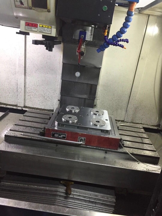
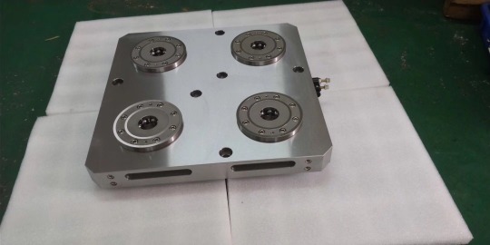
High-precision Zero Point Workholding solutions from Silvercnc are available to optimize your production procedures. Setup times are greatly decreased by our cutting-edge zero-point base plates and work holding systems, which offer remarkable accuracy and rapid changeover capabilities. These systems guarantee accurate alignment and safe clamping for a range of workpieces, making them perfect for CNC machining. At Silvercnc, we put efficiency, dependability, and adaptability first so that your production workflows may produce better outcomes. View our extensive selection of mechanical zero-point base plates designed to satisfy the demands of contemporary industry. Selecting Silvercnc's Zero Point Workholding solutions gives you a competitive advantage by lowering downtime and increasing productivity. Use our advanced products to improve your machining process right now! Please feel free to call us at +86 180 9892 0890 for any information.
0 notes
Photo

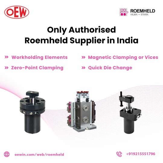
Need hydraulic workholding elements for your machines?
We are the distributor of roemheld workholding elements for jigs and fixtures, quick die clamping/changing elements, hydro-mechanical, mechanical, and hydraulic vices, magnetic clamping, and zero-point clamping solutions. For more details visit www.oewin.com
#Hydraulic Jack Manufacturer#roemheld suppliers in India#hydraulic vice manufacturers in india#hydraulic jack manufacturer in India
0 notes
Text
Leading Roemheld suppliers in India | OEW
Finding quality Roemheld products for your industry?
OEW provides the best production solutions in industrial manufacturing technology, assembly technology, clamping, and drive technology. They offer quality products related to a quick die change system for press machine, Roemheld workholding, hydraulic engineering services, and zero-point clamping solutions. Visit now!
#hydraulic vice manufacturers in India#hydraulic jack manufacturer#screw pump manufacturers in India#hydraulic cylinder manufacturer in India
0 notes
Photo
When you contact us about workholding components, rapid die change, zero-point clamping, magnetic clamping, or vices, you will have a great experience.
0 notes
Text
Cutting Tool in Turning Process
New Post has been published on http://www.cncmachinings.com/cutting-tool-in-turning-process/
Cutting Tool in Turning Process
Metal lathe turning is part of Klarm Machining service as it offers cheap cnc turning and milling metal machining factory work.
Cutting-Tool Installation
When mounting cutting apparatuses for turning machines, ensure that they face the right heading as indicated by the shaft pivot. In certain machines the apparatus will be situated straight up and in others, upside down. Continuously be certain that a mounted device is on focus. Some instrument holder connectors have a change component to calibrate the device’s tallness, while others require the utilization of shim material for change.
Opening working instruments can regularly require the most consideration during establishment and arrangement since their arrangement is basic. The device should be corresponding to the shaft pivot so the instrument’s body doesn’t rub within surface of the opening during machining. Some device holder connectors have squaring agents for this.
The equilibrium can be confirmed by running a dial pointer the long way along the device in two planes. Coolant lines ought to be associated and their spouts focused on the cutting zone after each device is mounted. Extraordinary consideration ought to be paid to guarantee that coolant spouts won’t meddle with the workpiece and workholding gadgets as the tomahawks move.
Cutting-Tool Offsets for Turning
When setting a cutting apparatus for a turning place, the area of the instrument tip should be characterized in the X and the Z tomahawks. This area is estimated as a separation from the turret reference position to the apparatus tip. When instrument estimations have been resolved, those apparatus balance estimations are put away in the machine’s math balance page. This page likewise contains a zone for characterizing information for device nose sweep size and quadrant direction.
As the cutting devices wear, the area of their forefronts changes. Wear counterbalances might be utilized to redress and adapt to wear as the apparatus is utilized during creation. Be certain that the wear balance an incentive for the balance number being set is gotten back to a standard of zero preceding figuring and entering the calculation esteem.
Apparatus Geometry Offsets
To decide the underlying apparatus length, the workpiece should initially have a set up work balance so the part face is Z-zero. For this progression, the workpiece root turns into the reference highlight decide the situation of the device tip.
For the Z-pivot, the running handwheel is accustomed to bring the apparatus tip to the workpiece face and ignite the part utilizing a piece of shim material or an antenna gauge. This positions the device tip at a known area comparative with the workpiece inception. For instance, if the instrument is ignited the part face of Z-zero with a 0.010″- thick shim, the 0.010″ shim thickness is deducted from the current supreme Z-hub position to compute the apparatus’ length counterbalance. Numerous controls make this interaction simpler by permitting the shim thickness to be gone into the math counterbalance page and will at that point figure the instrument length consequently. Setting the tolerance closely so as to get china precision cnc machining oem parts
This article is from http://www.cncmachinings.com/
#cheap cnc turning and milling metal machining factory work#china custom machine design#china customtitanium parts#china metal machining suppliers#china precision cnc machining oem parts#china steel tapped machining service suppliers#china titanium cnc turned parts manufacturers#cnc components companies#cnc lathe parts china#cnc precision brass parts china#cnc precision parts suppliers china#cnc turning and milling metal combined machining manufacturer suppliers#custom made metal cnc machining parts factory#high precision stamped parts suppliers china#micro-grinding machine factory#other machined ptfe manufacturers china#Featured Articles
0 notes
Text
Turning Speed Control
New Post has been published on https://www.cncmachinings.com/turning-speed-control/
Turning Speed Control
The span strategy might be utilized by cnc turning made in china rather than the bend place technique for recognizing the size of the curve when utilizing roundabout interjection. This technique is more normal and utilization a R-word to characterize the size of the bend span in the G2/G3 block. cnc turning stainless steel parts china show roundabout interjection for a section utilizing the range strategy.
The axle speed for china china custom CNC turning parts might be customized in one of two different ways. Direct RPM programming permits the shaft RPM to be straightforwardly modified at a fixed speed and is initiated with a G97 code. The shaft is begun utilizing a M3 for forward pivot and a M4 for invert revolution. M5 stops the axle. The square containing the axle start follows the protected beginning square of the program and resembles this: G97 S1200 M3 (SPINDLE ON CW AT FIXED RPM);
The drawback of this strategy is that the RPM should be determined and modified for each extraordinary width size.
An element called consistent surface speed (CSS) might be utilized all things being equal so the shaft RPM is naturally refreshed for every measurement being cut. With this element, the surface speed across the instrument’s forefront will remain steady. Programming a G96 code and giving the cutting rate in surface feet every moment (or meters per minute)activates thisfeature. WhenusingCSS, themachine refreshes the shaft RPM varying progressively by utilizing the tool’s X-hub position (which is the distance across being cut) and the surface speed customized. As the measurement being cut decreases, the RPM will increment.
Precision turning titanium parts suppliers utilizing CSS on little breadths can bring about higher axle speeds than what the machine or workholding gadgets can deal with, so a greatest RPM limit should be set. When programing CSS, the axle should initially be begun in direct RPM utilizing a G97 before steady surface speed is turned on. At that point CSS is initiated by programming two squares. One square cutoff points shaft RPM utilizing a G50 and a S-worth to set greatest RPM. The other square uses a G96 and a S-worth to enact CSS and set the cutting rate. When beginning the axle with a G97, it is normally best to program an underlying RPM that is near the one that will be utilized at the primary use of CSS. This will lessen the time and electrical energy required for the machine to change RPM when CSS is actuated. An illustration of CSS blocks following a shaft start resembles this:
G97 S1200 M3 (SPINDLE ON CW AT FIXED RPM);
G0X._ Z._ M8 (RAPID TO FIRST POSITION AND COOLANT ON);
G50 S_ (RPM LIMIT FOR CSS);
G96S_ (SET SFM FOR CSS);
Consistent surface speed isn’t utilized for holemaking activities (penetrating, reaming, tapping, subsetting, and so forth) since the customized X-hub organize of holemaking apparatuses stays at X-zero. Utilizing CSS here would promptly make the shaft run at the maximum RPM (G50) setting. Figure 8.3.14 shows a programming model utilizing CSS.
This article is from http://www.cncmachinings.com
#aluminum cnc machining suppliers china#automobile parts machining manufacturers china#big cnc machined part made in china#china carbon fibre cnc#china china custom cnc turning parts#china cnc plastic turning parts and service manufacturers#china cnc stainless steel turning service suppliers#china cnc steel turned machining parts suppliers#china customized cnc milling parts manufacturers#china machining plastic parts#cnc hotwire foam cutting china#cnc lathe parts companies#cnc machine for carbon fibre factory#cnc machining metal parts suppliers#cnc turning made in china#cnc turning part#cnc turning precision titanium parts factory#cnc turning stainless steel parts china#lathe turning parts factory#machining part made in china#precision micromachining factory#precision parts china#precision turning titanium parts suppliers#stamping parts#wilhelm schickard 1623#wire cut edm machine factory#wire cutting parts factory#Featured Articles
0 notes