#tube amplifier
Explore tagged Tumblr posts
Text

Lush sounding One owner 1965 Fender Vibrolux Reverb with original Victoria cover
#fender#vintage guitar#vintage electric guitar#vintage fender#tube amplifier#tube amp#Fender Amp#Vibralux
10 notes
·
View notes
Text
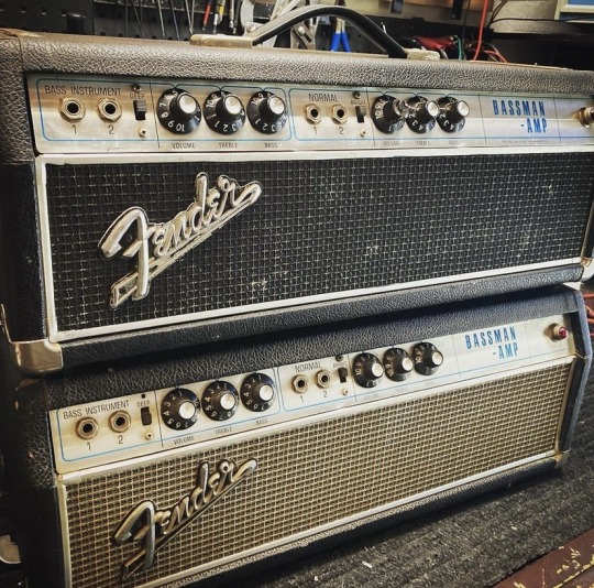
I love a good Bassman.
28 notes
·
View notes
Text
AM-Detection -the not easy way
Sometimes quite simple things can be a real nightmare if you take a closer look. One of those is AM detection. Your worst enemies are distortion and fading (the latter results in the first). The AM-Detector is only one little part in a receiver, exactly that kind of part usually no one thinks about. "It works, so what should be wrong with?" -a lot and sometimes there's more wrong than right.
A good part of that distinctive AM-Sound we all know is because of the Detector, even under the best conditions. If you're listen to shortwave or the broadcast band during the night then you also have to cope with Fading. Shouldn't be that problem, the automatic gain control takes care of that, right? Ehmmm... Yes. Sometimes. Why the sound gets so distorted when the signal goes down? Just because it's very often 'Selective Fading' and not just Fading -and your Detector doesn't like it.
Really good AM-Reception has a lot in common with High-End-Audio: if it shall work well EVERYTHING has to be well. So let's just talk a bit about Detectors...
Basically the Detector just splits the Audio Signal from the received and amplified Signal. Sounds easy and in fact it is -up to some degree. If you want more than this things getting complicated -really complicated. In at least 999 out of 1000 AM-Receivers for the Detector a small circuitry called 'Envelope Detector' is used, it's just a small Diode (Tube or Semiconductor), a few Resistors and small Capacitors. So, from the view of the Development Engineer: just put half a dozen cheap Components together and Bob's your Uncle. To tell the Truth: compared to the expense that thingy works surprisingly well. Because of this it's the 'Gold Standart' for this task since at least the mid 30s. But as good as it is, it absolutely has it's Limitations. Up to about 15...30% Distortion at a 100% Modulation Level is one, the inability to detect a signal with different sidebands (>selective Fading!) properly another.
To overcome these Limitations a thing named 'Synchronous Detector' was developed many Decades ago. This kind of Circuit has many advantages over the Envelope Detector, but to make one the complexity and the component count of those is just hilarious compared to the Envelope Detector. If only the result counts and nothing else: that's the way to go. We'll talking later how this exactly works, but before this you have to know that in a receiver with a Synchronous Detector also an Envelope Detector is needed: just for tuning in. So first we'll have a closer look how we can get the most ideal Envelope Detector.
Basically it's quite simple: want to have low overall Distortion? Feed it with at least 'a few' volts RF at it's input for having a high ratio between the input voltage and the 'forward voltage' of the Diode. Want low Distortion at low modulation levels? Use a Diode with low Impedance and a load Resistor with a value as low as possible. Want low Distortion at high modulation levels? Just make the input Impedance of the following Stage as high as possible for having the highest possible Ratio between the Resistance of the Load Resistor and the input Impedance of the following Stage.

The Receiver i wanted to use (R+S EK07) has an IF output, meant for exactly such things, the IF Level there's about 250mVpp @ 300kHz. So having everything above in mind -and just adding a 700mVpp IF output for the Synchronous Detector and an additional AGC-Circuitry, then we're coming to this:

The EK07 is a fully tube equipped receiver, so i also want to use tubes as far as possible and -like in the EK07- in a way which guarantees 10k's of Service hours. If at one point a Semiconductor may perform muuuch better -ok, so then. First of all i want high performance. So what tubes may perform optimal here?
For the first IF-Amp (IF1) not much is needed, the Gain is only about 3, the output voltage low and besides that it has to be an remote-controlled type. Selectivity isn't needed or desired, so no IF-Can, only a Broad-Band setup. Nearly every IF-Tube with a Transconductance of at least about 3000mhos (3mA/V) would do that job. To have better performance i took the EF805s, which is a Special Quality Version of the EF85 -or 6BY7.
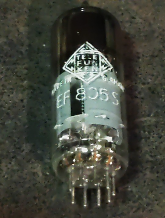
Transconductance is about twice what's needed, so we'll have Gain to spare, anyway, it's getting controlled with the AGC so it will work with less current which adds greatly to the service life. So no problems here.
For the second IF-Amp (IF2), things aren't exactly that easy. First: the output for the Synchronous Detector is placed between both Amps and has to deliver a constant voltage, so for the 2nd IF we need an Amplifier with an fixed Gain. A STABLE fixed Gain over long time periods. Further we want to have a relatively high and undistorted output voltage which calls for quite a bit of gain. Wait: there was also that thing with the low-value Load Resistor in the detector itself -so we also need a quite reasonable amount of output power from this stage. In Addition we want to have a stable gain for a time as long as possible. A IF-Tube like the EF805s could also handle this, but then we have to 'beat the crap' out of this thing. Not a good start for a long and stable service life, also not with Special Quality Tubes.
Because of all that my choice was a kinda 'special'-Special-Quality type: the E81L.

The datasheet calls this a 'Long range, Special Quality Tube for the use in Telephone Equipment'. Telephone Equipment? Like an answering machine?? Nope, by far not. Back in these days telephone companies needed to have Amplifiers for pushing the calls through loooong cables for long range service. But: this was all multiplex service, so they pushed dozens and dozens of calls simultaneously through one pair of wires or a Coax. The same way like for cable TV. THIS was these bulbs were meant for. For this task every company employed tens of thousands of such tubes 24/7/365. If a single one failed -most likely somewhere in nowhere of course- they had a problem. So they absolutely had to last.
These little bulbs are designed for about 4.5W plate dissipation at 20mA, the Transconductance is 11000mhos (11mA/V)-so it's about twice an usual IF Tube in every respect. So that's exactly what's needed here: a tube especially designed to last, quite powerful, so we can drive it with comfortable low settings, enhancing service life and stability much further.
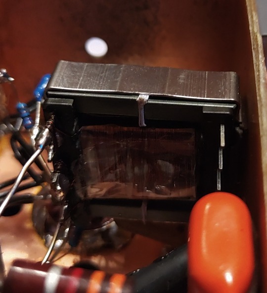
Because we need some amount of power the usual Broad-Band Amplifier arrangement (still: selectivity is not wanted or desired) with just a plate Resistor isn't good here, a suitable inductor works way better here. This has the further advantage that we can build it with a Tab like an Autotransformer -we don't need that much voltage it could deliver with that inductor by far, so this adds further to a good SNR and lower output Impedance. 300kHz trough a transformer? Yep, no problem. Just use the right core. Here it's not a laminated iron core but a ferrite one instead. Cause it's a single-A Amplifier of course we must add an air-gap, preventing saturation.
In a penthode stage the gain depends nearly exclusively on the Transconductance of the tube used, have to much just cut it down. The E81L has a quite high transconductance, about 3 times more than needed -and in the same order than big output tubes like the 6550, EL34 or 6CA7. For cutting that down to the desired level just put a Resistor or Pot in series to the bypass cap of the cathode Resistor. This acts as an series feedback so it also enhances linearity and long time stability greatly. Yap, i thought quite a while about which tube i should use here.
So after all Amplification is done now, we need a Diode for the Envelope Detector. Back in the Octal-Days this was the 6H6 / EB34, later in the Miniature-Days the 6AL5 / EAA91, both with two separate diodes in one bottle (or Can for the 6H6). These were not A DIODE, these were THE DIODE, so there's not much to choose from. Both are kinda close to each other, but are these ideal for what we want? They both can handle a reverse voltage of several hundreds of volts, so waaaay more than we need here. Both having a Plate Resistance of 600-something Ohms per System which is quite low -could be lower, even with both Systems in parallel. Of course these would be work well, no doubt about. But still.... Hey, this should be High-end so we're whining here at a very high level!
Basically we can use EVERY TUBE as a diode: just take the control grid as Anode, the Cathode as what it is and everything else as Shielding. We don't need hundreds of Volts reverse Voltage, nor high current, so also no big Cathode. We only want to have an internal Resistance as low as possible, so a close spacing between the Grid and the Cathode. This calls for a small Tube with a high Gm (or Transconductance) -like the 6AK5 / EF95. Can it handle the reverse voltage we need? Datasheet says 50V, so at least twice of what's needed. So just take one, put some current trough and take the voltage drop. Result: 210 ohms -way less than that what one of the double-diodes would provide, even with both Systems in parallel. Fits very well!

This is the soviet-military version of the 6AK5W / E95F. Special Quality. See these 'trenches' in the bulb? And the microscopic rivets holding the Plate together? The Soviets literally ruggedized the heck out of this tube! Why? Just because they used it widely in their Fighter Planes, ICBM's, Tanks and so on. Doubts about the soviet built quality? Hey, they wanted to win WWIII with them -so: nope. If you ever saw a ruggedized tube: this it is.
After the Detector itself is done, we come to last part of our little contraption: the buffer Amplifier. At the output of the Detector we have the AF as well with the overlayed AGC-Voltage and we want to have an input Impedance as high as possible for the Buffer Amp. Voltage Gain isn't needed -we have plenty of both from the Detector- so we just can use a Cathode Follower for the buffer. Ideally the Buffer should handle both voltages simultaneously, but then the output will be negative with respect to Ground. How to....? Simple: just put that thing between a positive and a negative supply rail. Then the output can swing freely between every positive or negative Potential as desired. Further: we don't need a Grid Resistor! The Grid just follows any voltage swing of the Detector, this also adds to a high input Impedance.
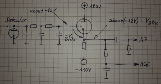
This Circuit will provide us a very high input Impedance, but this is High-End! So: what tube will be the best for? Because of the lack of any Grid Resistor the input Impedance depends now largely on the contact potential of the grid. So we want a tube with low contact potential which calls for a tube with a low Transconductance. Further we want a tube which needs only a low bias voltage for it's Grid, 'cause we'll loose any bias-volt in our AGC-Output voltage. This calls for a tube with an high Gain. Low contact potential and low Transconductance? High Gain?? That's the 12AX7 / ECC83! Ok, it's of course a double Triode, but we still can use the second system for something else -like for the Line-Output Amp. In that Stage there's not much needed so it also will perform well enough there -we're still talking about AM!
So let's put everything neatly together, adding adequate shielding and so on -and we get this:
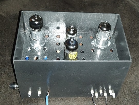
So now it's time to have a closer look we did everything right. Just put a 300kHz-Carrier in, 100% modulated with a triangle-signal. We should get a perfect Triangle at the AF-Output -if physics are with us. Due to the Triangle Signal any Distortion can easily be spotted on the Scope.
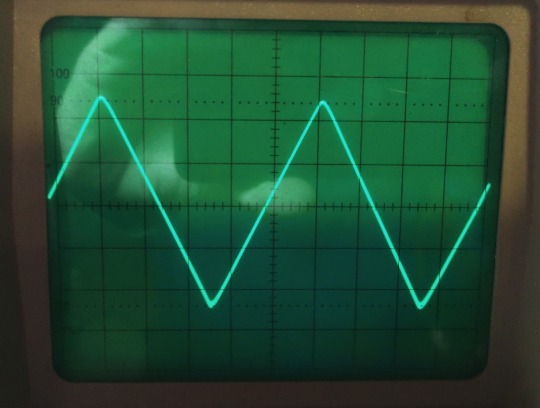
Looks promising! But somehow... Is the beam defocused? Let's take a very close look:

No, it's not. Those are just the very small remnants of the Carrier, so we actually have a look how the Detector works on a nearly 'microscopic' Level. I could take a measurement how much distortion we have left, but the Flanks of the Triangle are perfectly straight, so the Distortion will be really small -like 1% or so worst case. At least for the moment it's not worth the Effort. Compared to the usual 15...30% Distortion at a 100%-Modulation level this works really well, there's no doubt about.
So finally: we wanted to have a Envelope-Detector as good as possible and here we are. Ok, tbh it's better than needed, cause finally the REAL Detector will be a synchronous one. So why i took this that far? Easy: because of mental peace. Now i never have to think about if that part of the whole final thing could work better. As i said before: it's High-End.
Will update you if the next module is ready. But i fear this here was just the more easy part of the whole thing. From now on things may get a bit more tricky...
3 notes
·
View notes
Text
Let there be Rock 🎸.
#guitars#electricguitar#carvinguitars#kieselguitars#floydrose#guitarsolo#stevevai#guitarmania#guitarlick#lead guitarist#metalguitarist#carvin legacy#tube amplifier#home studio#blueguitar#shred guitar#guitarshredd
2 notes
·
View notes
Text
The Drama continues..
The ARC 60 is very much like a high maintenance girlfriend that you lust for. Lovely, frustrating and a lot of work.
The story today is I got the new tubes and put them in. I had all the covers off and the device was standing on its head. She is damn heavy. I am old but still fairly strong but I do not like having to lift her. Good thing I practice with my grand kids who still weigh less so far.
So covers off, on its head, meters attached, I put the new set of tubes in. Then you have to turn it on and hope for no smoke. At least that was a success. The voltage slowly crept up to 24mv. The target was 65mv. Let her warm up more, 20 minutes, 45 minutes. At an hour I try to adjust the bias. Turned all the way I got it to 45 mv. That is not good.
I wonder if the tubes would somehow wear in or something? The dial is turned all the way up, which cannot be good. I start looking at schematics. Did someone modify something? No it looks right. The thing was hand assembled, but it is factory neat. Ok turn it off and think. Think. Think.
Shut down and ask for advice. I sent an email to Audio Research support describing my situation. They got back to me next morning. Holy crap! I was a fan before, but that is what is called customer service! They built this thing 35 years ago! They did not have an easy fix, or maybe they did. They suggested the obvious. Put the old tubes back in and bias them. If that works it is the new tubes. The impedance parameter is too far off.
It takes a few hours to do the exercise so I will try that tonight. I hope it is that simple.
I have emailed The Tube Store asking about the matching parameter they use. It is based on a current draw under service conditions. The number on the tubes is 19. A number on the old tubes was around the mid 50s. No idea if that was the same parameter, but if it is, there is a possible solution. If they have sets of tubes with bigger numbers like 40 or above then I will exchange them and that was the problem.
The Franken-Amp just looks so satisfied with itself on the rack.
I supposed most people just have someone work on this stuff for them. All they see is the bill and the beautiful thing in the rack.
Tubes are expensive things.
1 note
·
View note
Link
Feliks Audio released their new 3rd gen OTL headphone tube amplifier called the EUFORIA evo earlier this year. A match made in heaven for high-load dynamic driver headphones? We find out in our latest review!
0 notes
Text


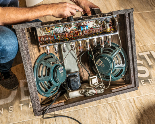
I'M IN LOVE - yeah I'm a believer!
1963 #Gibson#GA79 RVT Stereo amplifier (with 1972 #ES355 Stereo guitar).
If you are like me you never paid much attention to these vaguely funny-looking mid 60s Gibson stereo amps. To me they never looked like "real" rock n roll amplifiers, they looked more like the console record player my parents had in their wood-paneled mid mod living room back in the 60s. Part music box...but mostly furniture. I keep wanting to flip up the top and throw on a Neil Diamond LP!
But, I was dropping off some amps for servicing with my amp tech @marshalllespaulfan yesterday, and he had this one in his shop, in from another customer, and we tried it out with my Stereo 355...and all of a sudden EVERYTHING in my life made perfect sense!
This amp was MADE for this guitar...and I mean that quite literally. You plug it in using a special stereo "TRS" cable, switch the amp to "stereo" mode (although you can also use it in "mono" mode with a regular guitar and cable) and it's wired to give you the neck pickup in the left channel and the bridge pickup in the right channel. So you can set different volume, EQs, and effects for each pickup! Once each channel is dialed in, you can just flip your pickup selector between a grungy dark rhythm sound and a bright overdriven lead sound. OR...play them both at the same time on the center position, and have reverb and trem on the underlying bassy tone, but a crisp, clear, un-effected bright tone cutting through at the same time! It's GENIUS.
Because of its funky stereo wiring, my 355 has never been very heavily played 'round 'ere. The best you can do with it on a "regular" amp is plug its stereo cable into the two inputs of the same amp and even then it just sounds like a "normal" guitar. Without a TRS cable, only the neck pickup works on a "normal" guitar cable. So it's essentially useless. But with an amp like this, you can make it do SO MUCH!
I think I have found my next amp acquisition "quest"! 😉
#gibson#ga79#amp#amplifier#guitar amp#tube amp#vintage amp#gibson amp#vintage gibson#es355#gibson es355#es335#gibson es335#vintage guitar#guitar#guitars#guitar photography
69 notes
·
View notes
Text
youtube
"The World's Best-Sounding Power Amplifier" of 1977—Electrocompaniet's Surprising 52-Year History
#Electrocompaniet#Audiophile#Recommended#albumcover#vinylcollector#music#solidstate#tube#amplifier#poweramp#preamp#highend#mood#headphone#hifi#audio#vinylcollection#vinyl#record#vinyljunkie#vintage#art#vinylcommunity#vintageaudio#cd#cdcollection#dac#sacd#digitalaudio#Youtube
3 notes
·
View notes
Note
The Wrong Side of the Portal Raph from cabin 10 was wondering if you have enough water before you do anything fun!
"Raph wanted to swim with his family and maybe some new friends if you want to, but it's important to have enough water first. I have some extra water bottles if you need them!"
@tmnt-fandom-family-reunion

"Oh, cool!" Smokey gratefully accepted the water. It must have been refrigerated or had ice in it, because it felt cool in his hands. He smiled up at Wrong Side of the Portal Raph happily. "Thank you!"
Now for the...other part. Smokey nervously rolled the water bottle between his hands, but kept smiling. "And thank you for the offer, but I can't swim and don't really care for the ocean." And that was before he had a fire spirit take up residence in him. And before his cabin magically flooded. In the past, water had been okay, even when he couldn't swim, because he'd had his brothers with him. It'd been enough to quell his nerves. Plus, he had a big inner tube to hang out on!
Ever since Sparky had moved in, he'd gotten a lot less comfortable with it, even with his bros around. It'd taken his nerves and turned them into an outright aversion. Smokey did not like deep water or being submerged. He could handle shallows, but they were, well...shallow. No one could truly swim in them. He still had his inner tube, but floating around his with his bros had become a lot less relaxing and a lot more anxiety inducing.
The solution his family had found was letting him ride with one of them - normally Raph. It still made the box turtle nervous and Sparky hissed in his head like a cat being threatened with a bath, but being with someone he trusted wholeheartedly helped. It helped a lot too that if he was on Raph, he wasn't touching the water and had - in his mind, anyway - less of a chance of falling off. (He still clung to his brother like an octopus though.)
"Thanks though!"
#sparky = a fire spirit who dislikes water on principle. a giant cat.#mikey = never learned how to swim. scared of what could go wrong but trusted his bros enough to not worry about it.#sparky + mikey = fear is amplified into an anxiety and develops an outright aversion to any body of water deeper than his stomach#he honestly doesn't like the lazy river anymore but his bros tried so hard to find a way to make him comfortable#he doesn't have he heart to tell them#(the first time he rode the lazy river after sparky took him as a host he CLUNG to his inner tube like a scared cat)#(stiff as a board. staunchly refusing to look at the water. stared straight up the whole time. could NOT relax. nearly had an anxiety attac#sparky feels bad about it but they can't do anything about it. it's in their nature. they do NOT like water and they can't hide it#the bond gives away everything#the hissing thing was said as a joke but Mikey legit can feel how much Sparky does NOT like the water and it amplifies his own anxiety#now if sparky wasn't a fire spirit - he was just some random other spirit that didn't like water - it wouldn't effect mikey nearly as much#but hosting a FIRE spirit? causes changes#this is one of them#sparky au#cabin 15: fire nation#cabin 10#tmnt fandom family reunion#sports event
7 notes
·
View notes
Photo

2 notes
·
View notes
Text


Here are some pics of one of my latest repair : another vintage amp from the early sixties. It's a Stimer S17V (Stimer was a famous french brand in the 50's and 60's). The schematic looks a lot like the Stimer Nuance model. It's was a mess in it and the amp refused to turn on. Now it's fully working. I'll post the schematic in a few days.
#forge#hacker#maker#forge the maker#electronic#vintage#electronics#repairs and mods#tube amp#vacuum tubes#tube amplifier#stimer
4 notes
·
View notes
Text

(http://www.op316.com/tubes/myamp/data1.htm)
PMF-25Pは、比較的低い周波数帯域に微妙なピークとディップがある出力トランスです。無帰還時の特性をみても、51kHz付近に目だったピークがあり、43kHz付近、73kHz付近そして350kHz付近の3個所にディップがあります。各ディップのすぐ上には潜在的なピークの存在が想定されます。したがって、そもそもこの出力トランスで40kHz以上の帯域におけるフラットな特性は望めません。周波数特性をフラットにしようとして負帰還をかければかけるほど、ピークが頭を持ち上げてくるだけです。
無帰還時と負帰還時のデータは図のとおりです。この程度のわずかな負帰還では動作の不安定要素はなさそうなので、位相補正は全く行っていません。それでも周波数特性の暴れは生じていません。両端ともに落ちはじめのポイントがちょっと早いような気がします。それでも、わずかな負帰還で10Hz~40kHzで-3dBですので、これでよしとします。
このような特性を持った出力トランスの場合、周波数特性を伸ばそうとして負帰還量を増やすと、最初のピーク(50kHz付近)がむくむくと持ちあがってきてあっという間に0dBラインを越えてしまいます。そうなってしまうと波形は崩れ、耳障りな音に��ってしまいます。これを抑えようとして高域における強い位相補正を行うと、かえって周波数特性が劣化します。どうあがいても50kHzまで素直に伸びたフラットな特性は望めませんので割り切りも大切です。
ノグチ製トランスを使った「6AH4GT全段差動プッシュプル・ブレッドボード・ベーシックアンプ」の周波数特性
by Tetsu Kimura
3 notes
·
View notes
Text
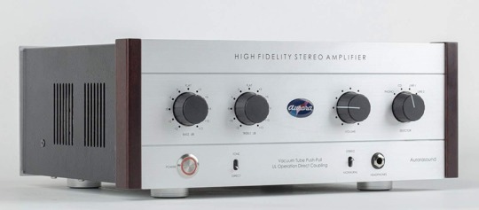
#audiophile#hifi#audio#audio system#hifidelity#technology#vinyl#new#news#listen#amp#amplifier#japan#review#aurora sound#valves#tubes
10 notes
·
View notes
Text

1952 Fender Princeton, TV Front, Rare early Tweed tube combo
12 notes
·
View notes
Text
Almost There.
The package has been delayed. I hope not because it got dropped and went tinkle tinkle. I hope it was just the van was too full.
Anyway there was a bit to do to get ready. I pulled off the top and bottom covers to the ARC beast. I tired to identify the test points for biasing. I found six little pins on the underside of the main board. They were close to where these resistors were placed on the top. ARC does a really nice job, but it would be trivial to LABEL the damn test points! I guess the factory knows what they are.
I reviewed the instructions twice over. They asked to put the leads on the resistor wires directly from the top. Access is really tight there and I would not even try it if the tubes were hot. You cannot reach in without touching the tubes. I got leads attached (cold) and they are a real pain. So I am thinking of putting outside jacks for the test points again. Shit, Dynaco did that 60 years ago. Yes there is about 400 volts there, but so simple.
I was able to confirm that the pins on the bottom were the correct places. So I labeled them.
I saw somewhere that amplifiers with rack handles were considered bad things by some sensitive people. In ARC amps they are for resting the beast on when you stand it on end. I had to do that with the preamp too. They are a bit industrial looking. But those guys do not work on their own stuff.
I will have to stand the thing on its head (on the handles) so I can place the leads on the test pins with the bottom cover off. The top cover is off to access the biasing pot. (geek speak for potentiometer.)
There was a moment of confusion because I can do math. The resistors are 0.5 Ohm. The bias current is 65ma per tube. The test voltage is 65mv. Err that is 130ma across a 0.5 Ohm resistor. Think think think.... Oh there are two tubes in parallel. That's OK then.
I got an air line and blew the dust out from everywhere. I looked at the tubes. The Philips 6550s were looking a bit tired. As were the front end triodes. I have a full set of Russian 6CG7s, so I popped them in. I put the tiny screws in a bag and placed the covers on loose and put the thing down on its feet.
I scrounged some speakers to give the thing a load just in case. Unloaded secondaries can surprise you.
It will take a bit to get this done. Warm up for an hour with the test leads connected. Track the current as it comes up. Check the voltages. Set the voltage on one side, check the other side. Check the balance on both legs. Wait a bit and repeat. Do not electrocute myself.
Take a breath. Shut her down wait a bit and replace the covers.
Then put her in the rack.
Vacuum tubes are high maintenance. Just like a very pretty girl who likes presents.
Solid State does not sound bad you know.
#audiophile#high end audio#cheap audiophile#tubes vs transistors#audio research tube amp#tube amplifier#6550 tubes
1 note
·
View note
Text
Fun $30 tube amp kit from CruncyTubeAmps.com
3 notes
·
View notes