#rs232 connector
Explore tagged Tumblr posts
Text
https://www.futureelectronics.com/p/semiconductors--signal-interface--rs-232/icl3221eivz-t-renesas-9034756
RS 232 cable, RS 232 voltage, Wireless USB, rs232 cable types
ICL3221 Series 250 kbps 15 kV RS232 5.5V Transmitter/Receiver - TSSOP-16
#Signal Interface#RS 232#ICL3221EIVZ-T#Renesas#communication#rs232 connector#RS 232 USB#RS 232 cable#RS 232 voltage#Wireless USB#rs232 cable types#RS 232 cable to USB#USB Full Speed#USB serial controller d driver
1 note
·
View note
Text
Sharing a Computer with More Friends
A few months ago I built an I/O expansion board for my homebrew 68030 project with a 4-port serial card to go with it, and got BASIC running for four simultaneous users. It worked, but not as well as I had hoped. I wanted to be able to run two of those serial cards to support 8 total users, but it had proven unstable enough that with just the one card I had to slow down the whole system to 8MHz.
So I designed a new serial card.

I had previously been running this computer without any issues at 32MHz with a mezzanine card with FPU & IDE as well as a video card. The main board by itself can clear 56MHz. Having to go all the way down to 8MHz just didn't sit well with me. I want this machine to run as fast as possible for its 8 users.
I put extra time into reviewing worst-case timing for all components and graphing out how signals would propagate. The 16C554 quad UARTs I'm designing around are modern parts that can handle pretty fast bus speeds themselves — easily up to 50MHz with no wait states on the 68030 bus — assuming all the glue logic can get out of the way fast enough.
Signal propagation delays add up quickly.
My first draft schematic used discrete 74-series logic for chip selection, signal decoding, timing, etc. At slower bus speeds this wouldn't have been a problem. But I want this thing to run as fast as possible. By the time critical signals had made it through all those logic gates, I was looking at already being well into one wait state by the time the UART would see a 50MHz bus cycle begin.
I needed something faster. I was also running low on space on the board for all the components I needed. The obvious answer was programmable logic. I settled on the ATF22V10 as a good compromise of speed, size, availability, and programmability. It's available in DIP with gate delays down to 7ns. Where discrete gates were necessary, I selected the fastest parts I could. The final design I came up with showed a worst case timing that would only need one wait state at 50MHz and none for anything slower.
It ended up being a tight fit, but I was able to make it work on a 4-layer board within the same footprint of my main board, putting some components on the back side. (It may look like a bunch of empty space, but there's actually a lot going on running full RS232 with handshaking for 8 ports).
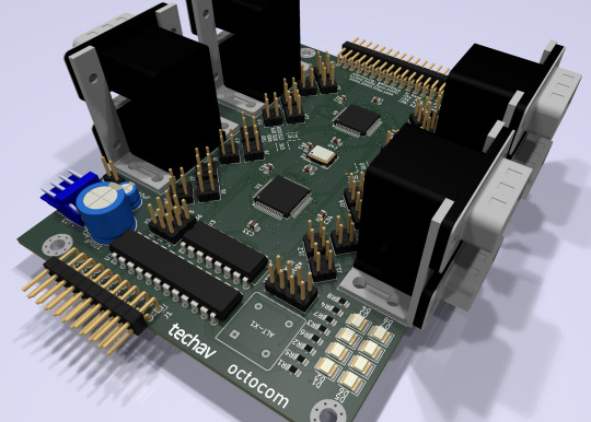
New problem. I had blown my budget for the project. As much as I love those stacked DE9 connectors, they're expensive. And there's no getting around the $10 pricetag for each of those quad UARTs. Even using parts on-hand where possible, I was looking at a hefty Mouser order.
[jbevren] suggested using ganged RJ45 connectors with the Cisco pinout instead of stacked DE9, to save space & cut costs. [Chartreuse] suggested buffering the TTL serial TX/RX signals to drive the LEDs that are frequently included on PCB-mount RJ45 connectors. Both great ideas. I was able to cut 20% off my parts order and add some nice diagnostic lights to the design.
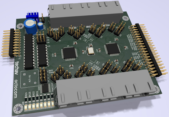
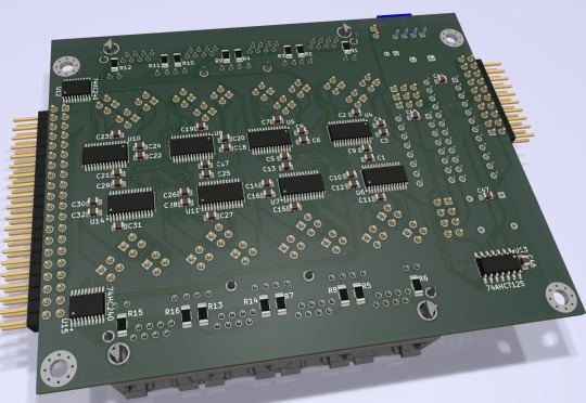
Two weeks later, I received five new PCBs straight from China. I of course wasted no time setting into starting to assemble one.
I really set myself up for a challenge on this one. I learned to solder some 25 years ago and have done countless projects in that time. But I think this might be the most compact, most heavily populated, most surface mount board I've ever assembled myself. (There are 56 size 0805 (that's 2x1.2mm) capacitors alone!)


After a few hours soldering, I had enough assembled to test the first serial port. If the first port worked then the other three on that chip should work too, and there's a great chance the other chip would work as well.

And it did work! After some poking around with the oscilloscope to make sure nothing was amiss, I started up the computer and it ran just fine at 8MHz.
And at 16MHz.
And at 25MHz.
And at 32MHz.
And at 40MHz.
And almost at 50MHz!
Remember what I said about my timing graphs showing one wait state for 50MHz? The computer actually booted up and ran just fine at 50MHz. The problem was when I tried typing in a BASIC program certain letters were getting switched around, and try as I might, BASIC just refused to 'RQN' my program. It was pretty consistently losing bit 3, likely from that signal having to travel just a tiny bit farther than the others. A problem that will probably be resolved with an extra wait state.
Good enough for a first test! A few hours more and I finished assembling the card.

I did have some problems with cleaning up flux off the board, and I had to touch up a few weak solder joints, but so far everything seems to be working. I've updated my little multi-user kernel to run all 8 users from this new card and it's running stable at 40MHz.
I need to update my logic on the 22V10 to fix a bug in the wait state generator. I would love to see this thing actually running at 50MHz — a 25% overclock for the 40MHz CPU I am currently running. I also want to expand my little kernel program to add some new features like the ability to configure the console serial ports and maybe even load programs from disk.
I hope to bring this machine with a collection of terminals and modems this June to VCF Southwest 2025 for an interactive exhibit that can be dialed into from other exhibits at the show.
#wrap030#multi-user BASIC#EhBASIC#homebrew computer#motorola 68030#68030#mc68030#motorola 68k#vcfsw#vcfsw2025#Retrocomputing#rtc#retrotech crew
28 notes
·
View notes
Note
Hi Foone,
I recently came into possession of a PERCON Falcon 320 handheld DOS terminal/barcode reader thing from 1998. It seems to complain about being unable to connect to a server, as well as some kind of firmware corruption, every time I reset it, and it seems it uses a nonstandard (with added power pins) 10-pin ethernet-shaped RS232 connector for interfacing. The configuration software seems to have downloads hosted only on very sketchy shareware sites (it doesn’t strike me as likely that Datalogic’s current software supports it, since the product isn’t listed on their website, only the newer Falcon X3). I can’t find any of the required cable on eBay, so it’s likely I’ll have to open it up and solder/otherwise jury rig some direct connection to something my computer can connect to via an RS232-usb adapter or something. Do you or anyone you know have experience flashing ROM/directly serially interfacing with stuff like this? The advanced user guide I can find by googling doesn’t give an exact spec on serial comms, just how to use the default config software and a pinout for the serial port, as well as how to use the DOS XFER command.
Sorry, not really. I usually have to find manuals or those rare adapter cables to get this stuff to work.
Good luck!
13 notes
·
View notes
Photo
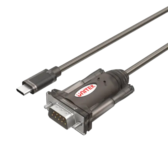
Unitek USB-C to Serial RS232 Cable UNITEK offers you the industry-use serial adapter with different connectors including this USB-C equipped adapter as well as USB-A equipped, and also RS232 and DB25M serial connector, to meet your needs Model Number: Y-1105K Product Overview: USB-C upstream connector Compatible with label writer, ISDN terminal adapter, printer Product Features: Support the conversion of USB-C to RS232. Link PC to Serial devices such as printer, label writer, ISDN terminal adapter. With USB specification v1.1. Flexible baud rate support up to 1.2Mbps. Bus powered, no external power supply needed. Hardware & Dimension: Color: Transparent Dark Brown Cable Length: 1.5M Upstream: USB-C Male Downstream: RS232 Male Package Contents: 1 x USB-C to Serial Cable Adapter
#USB_ADAPTER#ELECTRONICS#CABLES_CONVERTERS#ADAPTER#CNV_USB_C_SER_1.5M_U#SERIAL_CABLE#SERIAL_RS232#UNITEK#USB_C#Y_1105K
0 notes
Text
Price: [price_with_discount] (as of [price_update_date] - Details) [ad_1] Feature: 1. USB Full Speed Port: INLINE 6 can communicate with your PC via 9pin serial connector. Communication with your PC is also possible via Universal Serial Bus (USB) via a 4pin standard connector. 2. Data Link: The INLINE 6 adapter connects to the vehicle power supply, SAE J1708/J1587 data link, and two CAN/J1939 data links via a 25pin serial connector. 3. RP1210 Standard: INLINE 6 will work for INSITE, for PowerSpec and for Calterm III software applications. Can also be used with any other software application that is fully RP1210 compliant. 4. Easy Use: Each INLINE kit contains a data link adapter, basic cable and INLINE PC software driver. Load the software drivers, connect all the hardware, and you're ready to start a of data link adapters. 5. Long Durability: Attractive black powder coated aluminum housing provides sturdiness. Rated operating temperature from ‑40°C to +85°C meets stringent cab environmental testing requirements. Specification: Item Type: Inline 6 Data Link Adapter Kit Material: ABS, Aluminum Features: 1. Supports SAE J1708/J1587 and J1939/CAN data links 2. Both CAN ports auto detect between 250 and 500 kbps 3. Supports USB full speed port at up to 2Mrate 4. USB cable includes thumbscrews for secure mounting to INLINE 6 5. Supports RS 232 PC serial port at up to 115.2krate 6. Fully compliant with TMC's RP1210 standard 7. Small enough to fit in pocket 8. Attractive black powder coated aluminum housing provides ruggedness 9. Derives 8 V to 50 V DC power from vehicle 10. Controlled by advanced 140 MHz 32bit for processor for maximum speed and performance 11. Includes 6 LEDs to indicate status of power, USB, RS232, J1708/J1587, and two CAN communication ports 12. Both CAN ports support SAE J1939, SAE J2534, and ISO 15765 protocols 13. INLINE 6 is certified to meet European CE requirements 14. Rated for -40°C to + 85°C operating temperature 15 New in Box 100% Brand New Good Quality Durable and Eco Friendly Material. Package Contain Pack Of 1 Item. In case of any query please contact seller. [ad_2]
0 notes
Text
Buy HC05 Bluetooth Module at Affordable Price in Ainow
HC05 Bluetooth Module
The Bluetooth Transceiver HC05 bluetooth Module with enable/disable button Breakout is the latest Bluetooth wireless serial cable! This version of the popular Bluetooth uses the HC05 module. These modems work as a serial (RX/TX) pipe. Any serial stream from 9600 to 115200bps can be passed seamlessly from your computer to your target. The remote unit can be powered from 3.3V up to 6V for easy battery attachment. All signal pins on the remote unit are 3V-6V tolerant. No level shifting is required. Do not attach this device directly to a serial port. You will need an RS232 to TTL converter circuit or Arduino XBee USB Adapter if you need to attach this to a computer. You can either solder a 6-pin header or individual wires. The unit comes without a connector. Please see related male and female pins below. And now, we provide HC-05/06, HC05 bluetooth module could be set to Master or Slave by a user. HC-06 just be Master or Slave, that could be customized.
HC05 bluetooth module Applications:
Embedded Projects
Industrial Applications
Computer and portable Devices
GPS receiver.etc.
Note: Product Image may vary in terms of design and colour of the board
Features :
CSR Bluetooth Chip Solution-Bluetooth Spec v2.0 EDR Compliant
Enhanced Data Rate (EDR) compliant with V2.0.E.2 of the specification for both 2Mbps and 3Mbps modulation modes
Full Speed Bluetooth Operation with Full Piconet Support and Scatternet Support
Incredible small size with 3.3V input, and RoHS Compliant-UART interface and with baud rate setup function
Support for 8Mbit External Flash Onboard Support for 802.11Co-Existence. A range of operation: 8 – 10 meter.

0 notes
Text
Siemens 6GK5980-3BC00-0AA5 Serial cable
Siemens 6GK5980-3BC00-0AA5 Serial cable M12/RS232; Pre-assembled serial cable with M12 and RS232 connector; Length 3 m; 1 pack = 1 unit. Model: 6GK5980-3BC00-0AA5Categories: Industrial EthernetBrand: SiemensSiemens 6GK59803BC000AA5 Serial cableSiemens 6GK5980-3BC00-0AA5 Serial cable 100% New & Original. Quick Quote. Fast Delivery. Competitive Price. One year Warranty.Buy Siemens Industrial…
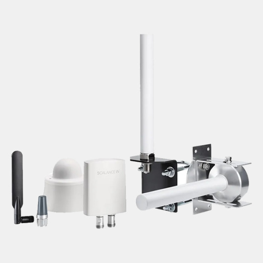
View On WordPress
0 notes
Text
In the Beginning: The History and Evolution of Device Servers

Lantronix PremierWave EN dual band WiFi device server
In the beginning (well the 1980s), there were terminal servers. And they were good. These devices allowed for dozens of ‘dumb’ terminals to be connected to a mainframe or minicomputer over a single wired Ethernet connection. They were widely deployed at banks, automotive dealerships and insurance companies - anywhere a concentration of computer users was to be found. One of the main benefits was not having to run yet another cable all the way from the main computer to the new terminal location. As these terminal servers advanced, they allowed for another level of authentication to be implemented, via local username and password. Savvy administrators started finding ways to also connect printers to these servers and ultimately, terminal server designers added direct support for print queuing. This was a substantial timesaver, as now the printer could be placed near the user without a dedicated drop. Since some printers were installed remotely without associated terminals, it was a natural extension to create a terminal server dedicated to attaching printers to the network. With this, the print server was born.
With the explosive growth of microcontrollers in products, a plethora of equipment that had serial connectivity began to emerge. Asynchronous serial was a well-established means of communicating with a computer and with the addition of a UART and line driver, it became easy for a designer to allow a way to interface with their new products. The problem then was that serial only worked well over 50-100 feet, depending on data rate. Someone came up with the idea of using a terminal server to connect these products (alarm panels, industrial equipment, medical devices, etc.) to the network. Most of the available terminal servers had high port counts (16, 32) so it was rather expensive to use a terminal server on the shop floor to hook one or two machines to the network. Lantronix solved this problem by creating 1-, 2-, and 4-port ‘serial servers’ as they were first branded, later coining the term ‘device servers’.
Initially, device servers were external ‘box’ products consisting of a small plastic or metal enclosure, which contained the serial-to-Ethernet conversion circuitry, regulated power supply, led indicators, Ethernet connector (RJ45) and the requisite RS232 connectors. Over the years, these boxes have shrunk in size and added additional interface types, including RS422 and RS485. Originally, the software enabled basic serial-to-Ethernet conversion (often called ‘tunneling’). As technology advanced, the firmware became much more configurable and for some applications, became protocol-aware. This was important because if data was not properly packed into a TCP (network) packet, it could become fragmented when arriving at the other end of the connection. This fragmentation could cause timeouts and other bad behavior from products and software used to having a direct connection.
In the late 1990s, web servers were added to device servers, giving them a new way of being configured and for data presentation. At this time, OEM manufacturers inquired about embedding device server functionality onto their main boards. Small products specifically designed for being embedded were created. These dispensed with the power supply regulation and serial interface circuitry. They were ideal for integrating to a main board, requiring only logic level power and signals. True to device server technology, they handled all of the tasks associated with getting a machine on to the network. It made networking easy for an OEM. In 2002, Lantronix changed the face of embedded device servers when they came out with the ultra-miniature XPort. This was a complete serial-to-Ethernet device with web server in a standard sized RJ45 jack (about the size of two sugar cubes). Millions of these devices have been deployed worldwide.
The next logical step was to branch out to additional transport types including wireless 802.11. Both embedded and external device servers have been produced utilizing the ever improving 802.11 standards. 802.15.4 and Zigbee have also benefited from the creation of embedded modules.
While many additional customer interface standards have been created, asynchronous serial is still the most common way device servers are connected to equipment, both in embedded and external applications. More recently, SPI has become interesting for high-speed transfers from an OEM main board to an embedded device server, as well as 802.3 wired Ethernet (“bridging” to 802.11 wireless).
Where are device servers headed? Physical size reduction is always foremost on the list. Also having faster ways to interface to an embedded device (i.e. SPI, USB, etc) to improve overall bandwidth. It has been imperative to add additional compute power and memory resources for tackling increasingly complex encryption and authentication methods. This extra ‘horsepower’ has obviated the need for a main processor in some embedded applications. It’s funny to think that just eight years ago, a device server might be able to execute 30 million instructions per second. Now it is upwards of 400 million! Additional I/O capabilities allow a wider variety of sensors and other peripherals to be attached to a device server. And of course, keeping up with the latest standards in wired and wireless communications is a must. Device servers have come a long way, but the goal remains the same: Handle all communication tasks from A to Z, whether wired or wireless, and provide a very easy-to-implement solution that keeps the customer focused on their core business and gives them a huge time-to-market advantage.
0 notes
Text
USB to RS232 Adapter Digitus DA-70156
If you’re passionate about IT and electronics, like being up to date on technology and don’t miss even the slightest details, buy USB to RS232 Adapter Digitus DA-70156 at an unbeatable price. Colour: Black Connector: Male Plug Connections: USB RS-232 SKU: S9104721

View On WordPress
0 notes
Text


Model F238OT-I-LL1 is a high-performance all-in-one open frame monitor equipped with a CPU Cortex-A17 quad-core, DDR 2G, ROM 16G and a projected capacitive touch screen based on the ROCKCHIP RK3288 high-performance application processor platform. It is a product that can be used widely. The current basic product provides 4 USB 2.0 ports, but upon user request, up to 9 USB 2.0 ports and up to 4 RS232 serial ports can be provided. Video out function for screen expansion is provided through HDMI port, 10/100M Adaptive Ethernet RJ45 connector and Wi-Fi/Bluetooth function are provided. In particular, useful tools for kiosk and banding machine functions are provided in the form of apps by default, providing user convenience such as automatic power on/off management of the system / automatic execution of specific apps.
SUFFIX "B84N" is
HDMI video output.
With P-CAP touch screen (IN CELL TYPE).
IPS family wide viewing angle
Mini SD slot provided (Upto 128G)
0 notes
Text
HDMI switch and multi-viewer switcher. Should I buy a more functional device right away?
You must connect multiple video sources to a TV with only one HDMI input. Switching the HDMI cable is inconvenient and causes wear and tear on the TV connector and its repair. Instead, your best choice is to buy an HDMI switcher. This device usually has several HDMI inputs and one HDMI output. You can switch sources using the buttons on the front panel or with an IR remote control. Some switchers have an RS-232 port for connecting external control systems.
When looking for an HDMI switch in stores, you may find a more advanced device, the multi-switch, which costs a bit more. What is it? Is it a good buy? Let's find out.
HDMI switch. General view
What is an HDMI switch, and how does it work, using the INRIKS SW4031 (analog is Lenkeng LKV301-V2.0) as an example? The device has 3 HDMI inputs for connecting video sources (laptop, TV set-top box, video recorder, etc.) and 1 HDMI output for connecting a monitor / TV / projector. The maximum resolution is 4k@60fps.
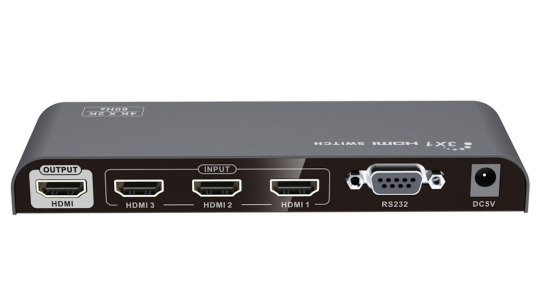
The device is shipped in a cardboard box. This is the usual packaging of devices for the professional consumer. Mass-market products are often packaged in boxes with colorful prints.
The Switcher has a compact size. The bottom of the package contains the IR remote control, a 5 V power adapter, and instructions.


All connectors are located on one side. This feature simplifies the wiring organization. In addition to the HDMI ports and the input for the 5V power adapter, there is an RS232 port. This is another attribute of professional orientation. The device can be connected to various control systems. For example, to control audio/video complex with one console, touch screen, or for automation (running some scenarios). This extensive theme is better explored in more detail in a separate article.
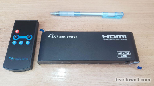
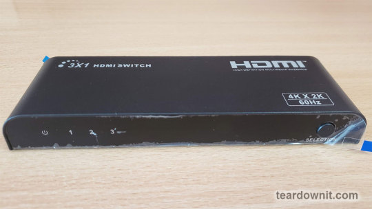
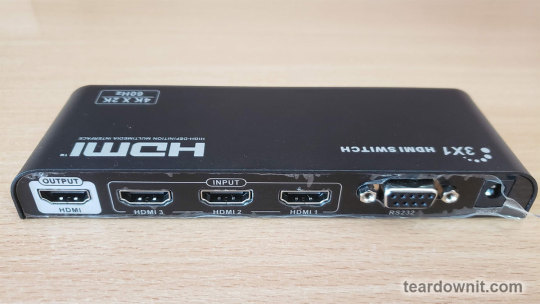
The status indicators (on/off, active input) and the input switching button are on the front side.
The remote control has a minimum button count.
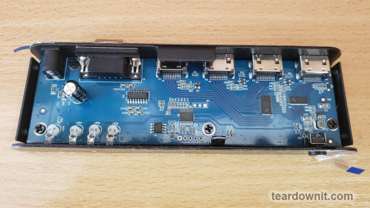
The case is made from thick metal and feels very monolithic in the hands. The connectors fit very well. The gaps are minimal.
The soldering of elements and connectors is neat.
HDMI switcher. Performance testing
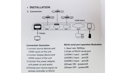
According to the diagram, we connected three laptops and one monitor to the switch.

We found a delay of several seconds when turning on the first input. The same delay is also present when connecting the laptop to the TV directly. It is explained by the two devices matching, which takes time. The picture quality is excellent.
We see the same delay when we switch to the second and third inputs. When switching back to the first input, we see the same delay again, i.e., the matching process happens repeatedly.
This switching is common to all low-cost HDMI switchers. If the long switching time is unacceptable, you should look for a device with Seamless Switching. This function is necessary to switch between cameras during live broadcasts on the Internet.
You can select the desired input or scroll through all video sources individually with the remote control.
The manual contains a port setting description and switching commands for RS232 control:
HDMI multi-viewer switcher. General view
What is a multi-viewer switcher, and how does it work (using INRIKS SW4041MS (analog is Lenkeng LKV401MS) as an example)?
This device has four HDMI inputs for connecting various video sources (TV set-top box, DVR, laptop, etc.) and one HDMI output for connecting a TV. The maximum resolution is 1080p@60fps.
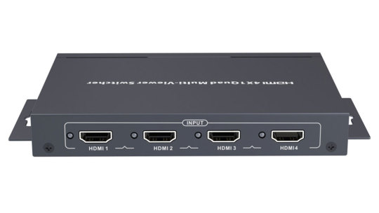
The SW4041MS multi-switch comes in a similar cardboard box as the regular switch. The package contains the multi-switch, a 12V power adapter, a removable surface mount, and instructions.

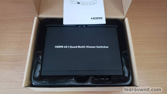
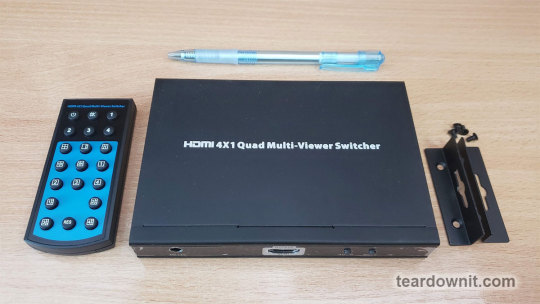
Unlike the usual switch, the SW4041MS has HDMI and power cable connectors on both sides. Four HDMI inputs are on the rear side. One HDMI and a DC 12V power input are on the front side. The control buttons and the IR receiver are also on the front side.


Brackets for attaching the multi-switch to different surfaces are included. This is a big plus to the installation possibilities.


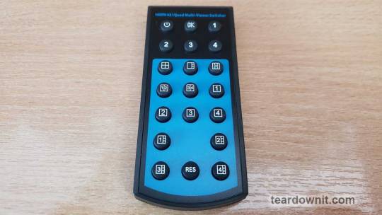
The remote control has a large number of buttons for flexible device control.
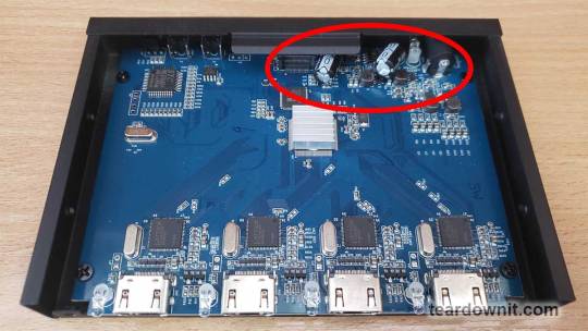
Multiswitch's housing is made from quality metal. The soldering of elements and connectors is neat.
But we do have a small comment about the location of the capacitors. They clearly tried to fit into a small space. Although this element feature does not affect the performance. We don't have any complaints about other elements.
HDMI multi-viewer switcher. Performance testing
According to the diagram, we connected four video sources and one monitor to the multi-switch.
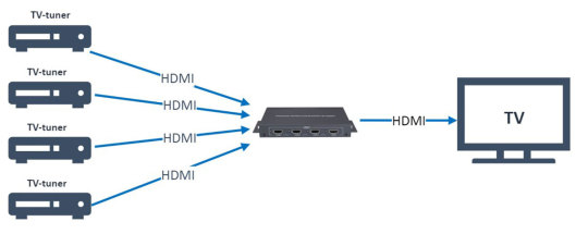
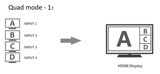
According to the manual, in addition to the classic switcher function, the device under test has a multi-viewer function - the simultaneous display of one, two, or four video sources on the screen.
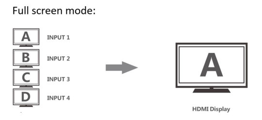



We switched inputs and saw instantaneous switching without image crashes or pauses in full-screen mode (classic HDMI switcher). This surprised us. Usually, devices with this ability cost many times more.
However, we quickly found the "price" of a quick switch. We have decided that the video bit rate is reduced. It is a slight distortion of colors. The multi-switch slightly distorts the image. When displaying standard video, the distortion is almost invisible. But if you display the laptop desktop, the distortion becomes more noticeable. For example, dividing lines in some programs, which were barely detectable in the original image, have disappeared.

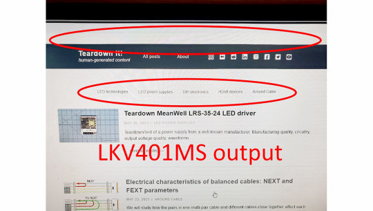
When testing the multiscreen function, we concluded that you can actually use «Full-screen mode» and «Quad mode – 1».
In other modes, the multi-switch distorts the image.
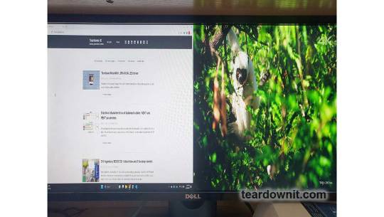
In addition, we want to draw your attention to sound. In multi-mode, you can separately specify from which source the sound is output. This is very convenient.
Conclusions.
The choice is simple.
Case One.
You want to connect multiple video sources to one TV (projector) and switch between them. It would be best to choose a standard HDMI switcher (e.g., SW4031) without additional functions.
Case Two.
Your task is to display multiple video sources simultaneously without high image quality requirements. For example, to view multiple video recorders at the same time. You can buy a cheap INRIKS SW4041MS multi-viewer switcher. But this device distorts a video image's color and aspect ratio.
1 note
·
View note
Photo
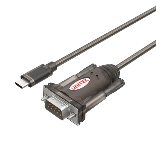
Unitek USB-C to Serial RS232 Cable UNITEK offers you the industry-use serial adapter with different connectors including this USB-C equipped adapter as well as USB-A equipped, and also RS232 and DB25M serial connector, to meet your needs Model Number: Y-1105K Product Overview: USB-C upstream connector Compatible with label writer, ISDN terminal adapter, printer Product Features: Support the conversion of USB-C to RS232. Link PC to Serial devices such as printer, label writer, ISDN terminal adapter. With USB specification v1.1. Flexible baud rate support up to 1.2Mbps. Bus powered, no external power supply needed. Hardware & Dimension: Color: Transparent Dark Brown Cable Length: 1.5M Upstream: USB-C Male Downstream: RS232 Male Package Contents: 1 x USB-C to Serial Cable Adapter
#USB_ADAPTER#ELECTRONICS#CABLES_CONVERTERS#ADAPTER#CNV_USB_C_SER_1.5M_U#SERIAL_CABLE#SERIAL_RS232#UNITEK#USB_C#Y_1105K
1 note
·
View note
Note
I've also seen these on custom AV installations where a single large cable is used to run a number of different signals a decent distance, and then breaks out into a cable like this on either end. I've personally installed some that use a half inch thick cable terminating on both ends with a DB25 connector, and a breakout cable that has two RCA composite video, RCA mono audio, RJ45 PTZ camera control, RS232 terminating in a DB9. Here are some of the cable diagrams for those cables:

Cable T511 was 50 feet of 1/2" thick cable. It was a beast to run, and we'd usually have at least 2 of them.
Here's another cable diagram for another of the cables that came in the kit:

For those interested in learning more, this is from the Tandberg Educator MXP classroom video conferencing system. https://www.clarybusinessmachines.com/products/files/tandberg/tandberg_educator_mxp_user_manual.pdf
any idea what this cable is?
looks like 9-pin vga on one side then breaks out into 7 wires labeled composite? on the composite side, one red wire is labeled "Composite Sync Output", one blue is labeled "C/V Sync Output", one green is labeled "Y/H Sync Output", and the black wire is labeled "Composite Video Output". the cable itself has a tag that says "cable from splitter to monitor"
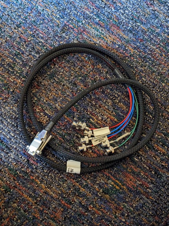

That's probably designed for some specialist video card that generates output for professional video production. That's why it's got separate syncs, because that's often needed to properly genlock all the stages.
No idea what specific card it is, or what device you'd plug it in, but this is the kind of cable that gets custom made for one specific card type and the next card will use a completely different cable, so both the cable and the card are useless when they get separated, as they inevitably do :(
104 notes
·
View notes
Text
Access Serial Devices on the Go With Tibbo WebUSB Boards
The RS232 and RS485 interfaces remain widely used in the industrial world because of their reliability, cost-effectiveness, and simplicity. However, servicing devices via a serial port usually entails lugging around a laptop. This means that even simple tasks, such as upgrading firmware, can be real chores — particularly if the device is in a remote or hard-to-reach place.
Tibbo's WebUSB boards make it much easier and more convenient to work with RS232 and RS485 devices — especially in the field. The Web232 board features an integrated DB9M connector, while the Web485 is equipped with a four-pin terminal block. On the other end, a single USB Type-C port powers the board and implements a data link with your PC or Android device!
The boards are designed to work with WebUSB, an API developed by Google. WebUSB enables accessing USB devices from Chrome and a few other browsers. This allows for the creation of USB-enabled web apps. For example, several Tibbo Web Apps utilize WebUSB to configure our RS485 Modbus Sensors, also known as Bus Probes.
Watch the video below to see how incredibly straightforward working with serial devices can be with a WebUSB board. In it, we use a Web485 board and an Android smartphone to poll a Bus Probe #05 flood/leak sensor.
youtube
And what if you want to do more than just some routine maintenance or configuration? Do you need a full solution that can be deployed on a smartphone or tablet? In this case, you can build a customized web app! Tibbo supplies the WebSerial Library to simplify and speed up the development of web apps that use our WebUSB boards.
0 notes
Text
If you do not have the serial cable bundled with the Cybiko, you should know that they’re practically impossible to find. If do not mind making a small after-market modification to the Cybiko, you will need to do some soldering work to add some wires, which we will later attach to an RS232 port. This is necessary because Cybiko used a proprietary connector and as far as I can tell no other device used this connector, and therefore the cables are becoming quite rare.
1 note
·
View note
Text
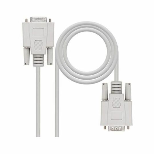
Cable NANOCABLE 10.14.0202 PUERTO SERIE DB9 RS232 1,8 M
If you’re passionate about IT and electronics, like being up to date on technology and don’t miss even the slightest details, buy Cable NANOCABLE 10.14.0202 PUERTO SERIE DB9 RS232 1,8 M at an unbeatable price. Type: Adaptor Cable Converter/Adapter Colour: Beige Cable length: 1,8 m Certificate: RoHS RS232R serial cable with DB9 male connector on one end and DB9 female on the other Product…
View On WordPress
0 notes