#red_color
Explore tagged Tumblr posts
Photo
Im Human

光の競演 Light Competition #夜景 #night_view #すみだリバーウォーク #Sumida_River_Walk #隅田川 #Sumida_River #赤 #red_color #青 #blue_color #金 #gold_color #映り込み #リフレクション #reflection #反射 #ハレーション #halation #明かり #灯り #屋形船 #coverd_boat #sony #xperia https://www.instagram.com/p/Cma_HvcLT5D/?igshid=NGJjMDIxMWI=
#夜景#night_view#すみだリバーウォーク#sumida_river_walk#隅田川#sumida_river#赤#red_color#青#blue_color#金#gold_color#映り込み#リフレクション#reflection#反射#ハレーション#halation#明かり#灯り#屋形船#coverd_boat#sony#xperia
1 note
·
View note
Photo

It took us about half a day to get to this beautiful valley in the middle of the #high_atlas_mountains, it's just #stunning #beautifullandscape #instagramers #wonderlusting #morocco #maroko #marrakesh #marruecos #atlasmountains #breathtaking #awesomepic #fabilousbeauty #instaphotograph #photographe #beautifullandscape #colorful #red_color #blue_sky #remote #Berberlife #amazigh_people #awesome_earthpix #Mount_toubkal #hiking_hobby #hiking_in_morocco #hiking👣 #hikingaddict #hikingtrail #hikingworldwide #hikingadventures #nature #naturephotography #natur #travelgram #traveling #traveladdict #discoverysport #discovertoghether #discovertogether https://www.instagram.com/p/B0mJM4uDyeH/?igshid=17by51ijd5oqr
#high_atlas_mountains#stunning#beautifullandscape#instagramers#wonderlusting#morocco#maroko#marrakesh#marruecos#atlasmountains#breathtaking#awesomepic#fabilousbeauty#instaphotograph#photographe#colorful#red_color#blue_sky#remote#berberlife#amazigh_people#awesome_earthpix#mount_toubkal#hiking_hobby#hiking_in_morocco#hiking👣#hikingaddict#hikingtrail#hikingworldwide#hikingadventures
0 notes
Photo

#red_color #white_color #shirts #designer #chinese #roundneck #stylish Catalog Name: *Vintage Ethnic Cotton Men's Shirts Vol 14* Fabric: Cotton Sleeves: Sleeves Are Included Size: M,L,XL,XXL (Refer Size Chart ) Length: Refer Size Chart Type: Stitched Description: It Has 1 Piece of Men's Shirt Work: Printed Dispatch: 2 – 3 Days Design: 5 Easy Returns Available in Case Of Any Issue https://www.instagram.com/p/ByR_f28Bmtv/?igshid=h7jmwd9iftsj
0 notes
Photo
#SUPPORTARTISTS Regrann from @marysiabieniaszewska - #minimal_poland #red_love #red_color #minimal_mextures #minimal_experience #minimalism_world #minimal_poetry #minimal42 #minimal_abstract #minimal_textures #obscure_lens #minimal_hub #colour_me_creative #minimalzine_organica #minimalzine #minimalist #minimal_masters #loveminimalism #minimal_love #tv_minimal #tv_minimalism #pocket_minimal #ig_mnms #ig_minimalshots
#minimal_mextures#minimalzine#red_color#minimal_hub#colour_me_creative#ig_minimalshots#minimalzine_organica#minimalist#tv_minimal#minimal_textures#minimal_love#tv_minimalism#red_love#minimal_masters#minimal_experience#pocket_minimal#ig_mnms#minimal_poetry#minimal_poland#supportartists#minimalism_world#minimal_abstract#obscure_lens#minimal42#loveminimalism
0 notes
Photo

Those details... /// Esos detalles... #alejandrocamposphotography #DCkina #macrophotography #macro #macro_holic #HD_macro_lens #mobilephoto #mobile #motorola #instagram #instacool #followme #naturephotography #costa_rica #red_color #flower #contrast #daylight #picoftheday #awesome #awesomeday #product_reviews #reviews (en Lagunilla, Costa Rica)
#reviews#dckina#red_color#daylight#mobile#instagram#macrophotography#costa_rica#hd_macro_lens#product_reviews#macro#flower#awesomeday#followme#awesome#picoftheday#contrast#instacool#naturephotography#motorola#alejandrocamposphotography#mobilephoto#macro_holic
0 notes
Photo

Dead stories
0 notes
Text
Pixel LED - Fireless Cracker Tree with Sound & Code, Arduino Programming & Coding
Pixel LED – Fireless Cracker Tree with Sound & Code, Arduino Programming & Coding
Following is the CODE to copy & Paste in Arduino IDE Sketch:- #include <Adafruit_NeoPixel.h> #define neo_pixel_pin 6 #define number_of_neo_pixel 47 #define piezo 5 #define dimmer 30 long freqIn; long blow1; long blow2; unsigned int last_num =0; int brightness = 128; Adafruit_NeoPixel strip = Adafruit_NeoPixel(number_of_neo_pixel,neo_pixel_pin, NEO_GRB + NEO_KHZ800); uint32_t red_color =…

View On WordPress
#ARDUINO UNO#CODING for cracker tree#DIY Electronics fireless cracker tree with sound for School projects#Electric Uncle Hatwale#Electronics fireworks with sound#ESP8266 NodeMCU 12E#Free Code for Oixel Led Cracker Tree & Chakari#Free Education Platform#LED STRIP PIXEL PROGRAMMED DECOR LIGHTING EFFECTS#Multitech Education for you#PIXEL LED LIGHTING EFFECTS WITH SOUND ARDUINO BASED#Programming and Coding for fireless cracker tree#SOUND
0 notes
Text
Using STONE TFT LCD Control WS2812B_RGB lamp
Using STONE TFT LCD Control WS2812B_RGB lamp
This article documented the process of controlling the WS2812B_RGB lamp using the STONE display module.
This project is to achieve RGB lamp control:
1. Change the color of the light
2. Change the brightness of the light
3. Change the four modes of the lamp

STONE TFT-LCD
The STONE STVC070WT-01 is a 7-inch display module with a resolution of 800*480.This display module can be purchased from the official website of STONE. The communication mode is uart-rs232 and uart-ttl.The development method is very simple, MCU only needs to send instructions to STONE display module to control the display content through UART. In the same principle, when the user touches the STONE display module, the display module also sends relevant instructions to MCU through UART, and MCU then controls the device (WS2812B_RGB lamp in this project).
STONE STVC070WT-01
The following picture shows the package and accessories I received:
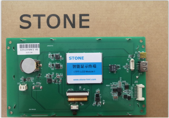

LIST:
1. Connection and interface
2. USB to TTL adapter plate
3. Usb flash drive (including development information)
4. Micro USB cable
5. USB transfer board
6. STONE STVC070WT-01 display module
7. 12V power adapter
The function of the STONE TFT LCD
- built-in Cortex CPU and driver
- can be controlled by any single chip microcomputer
- show pictures/text/curves
-65536 color TFT display
- can be touched
- RS232/ RS485/ TTL UART interface and USB port
- wide voltage range
How the STONE tft-lcd display module works
The tft-lcd module communicates with the customer's MCU through commands (hexadecimal code), and the MCU then controls the connected device to work according to the commands received.
The development steps for the STONE module
Use STONE's tft-lcd module in only 3 steps:
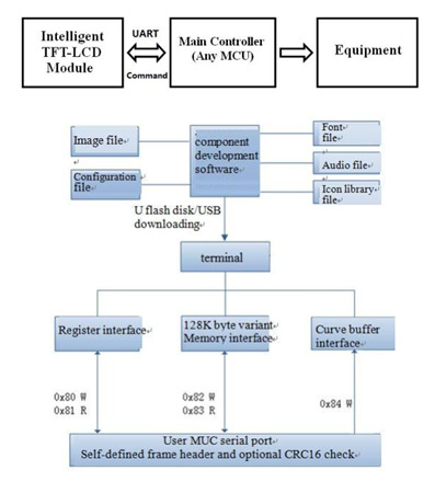
l Design a beautiful set of graphical user interfaces.
l Connect directly to the client's MCU via RS232, RS485 or TTL.
l Write a simple program, by the MCU command control TFT-LCD module.(hex).
TFT LCD module serial command frame consists of 5 data blocks, all serial command or data are expressed in hexadecimal format.Data transfer in MSB mode.For example, for 0x1234, first send 0x12, then 0x34.
Application scenarios of STONE tft-lcd display module
The following 9 application scenarios are described on STONE's official website:

STONE display module is widely used in various industrial fields, such as:
Medical beauty equipment, construction machinery and vehicle equipment, electronic instruments, industrial control system, power industry, civil electronic equipment, automation equipment, transportation.
UI image design for STONE TFT-LCD
The interface designed by using Photoshop is as follows:
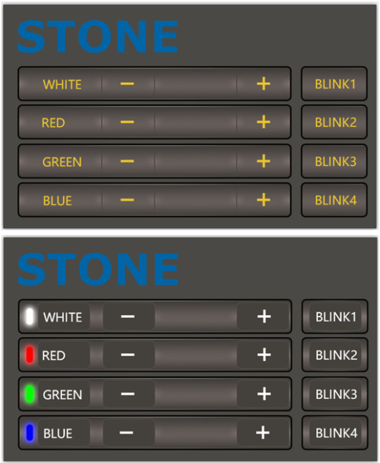
The first picture is the main screen picture, and the second picture is the effect when the button is pressed.
Use TOOL2019 software to generate LCD module configuration files
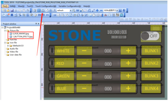
Click the button indicated by the arrow to generate the configuration file, and then download the configuration file into the display module to display the UI interface we designed.
This part of the content and tutorial I do not go into detail, you can go to STONE website to download a very detailed tutorial.
Wiring and welding
Having completed the touch display control above, we can focus on the development of MCU and WS2812B_RGB lamps.
But before that, we need to do some welding.
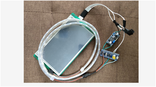
Wiring diagram
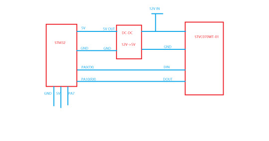
The power adapter is 12V, which needs to power the STONE STVC070WT-01 display module and to power the MCU module and WS2812B_RGB lamp by lowering the voltage to 5v through the dc-dc buck.
Accessories used in the project

Main accessories are:
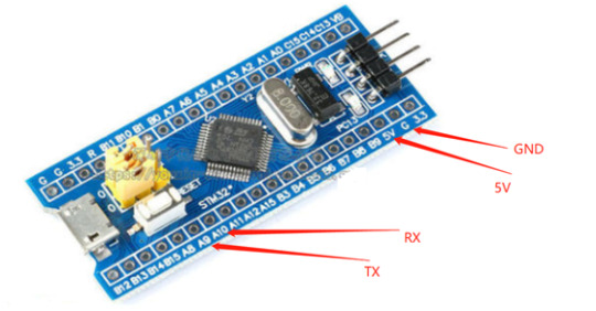
1. STM32F103C8R6 module
2. Dc-dc buck module
3. UART connection
Since the communication mode of STONE STVC070WT-01 is uart-ttl by default, we do not need the RS232 interface for the connection connection. Remove the RS232 interface:

welding
Weld these parts together and the effect is as follows:
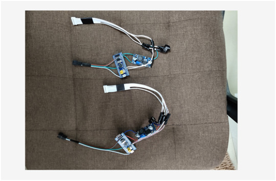
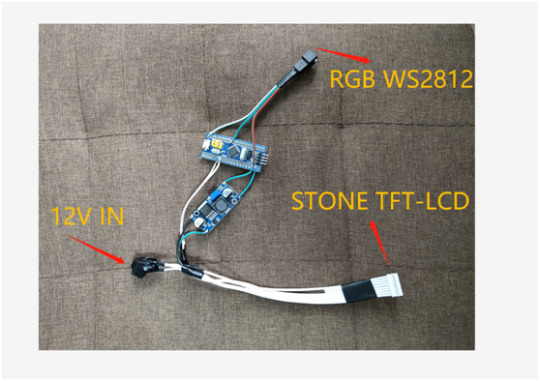
There are three interfaces, as shown above.
When this part is ready, you can program the MCU.But before we do that, we need to determine how the WS2812B_RGB lamp will be driven.
WS2812B
WS2812B is actually an RGB driver chip.
The control circuit and RGB chip are integrated in a 5050 package of components to form a complete pixel point.
Built-in signal shaping circuit, any pixel received the signal after waveform shaping output, to ensure that the waveform distortion of the circuit
Accumulation.
Built-in power on reset and power off reset circuit.
The color of each pixel can achieve 256 levels of brightness display, complete the full color display of 16777216 colors,
Serial interface, can complete data reception and decoding through a signal line.
The transmission distance between any two points is no more than 5 meters without any additional circuit.
When the refresh rate is 30 frames/SEC, the cascade number of low-speed mode should be no less than 512 points, and that of high-speed mode should be no less than 1024 points.
Data transmission speed up to 8Kbps.The color of the light is highly consistent and cost-effective.

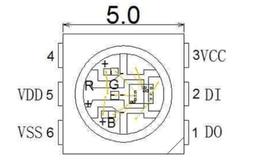
1 DOUT: Data output, control data signal output
2 DIN: Data input, control data signal input
3 VCC: Logic power supply, control circuit power supply
4 NC
5 VDD: Power supply, LED power supply
6 VSS: GND
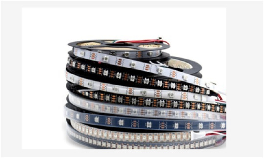
Application field
LED full-color light string, LED full-color module, LED full-color soft light bar hard light bar, LED guardrail tube, LED point light source, LED pixel screen, LED special-shaped screen, various electronic products, electrical equipment running horse light.
Driver for WS2812
The driving mode of WS2812 is simple. MCU only needs a signal line to complete the brightness and color control.

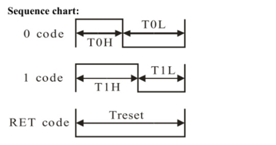
STM32 driver code
#include "../BOARD/ws2812/ws2812.h"
#include "usart.h"
#include "delay.h"
uint8_t PIXEL_NUM=60;
#define RGB_LED GPIO_Pin_7
#define RGB_LED_HIGH (GPIO_SetBits(GPIOA,RGB_LED))
#define RGB_LED_LOW (GPIO_ResetBits(GPIOA,RGB_LED))
void RGB_LED_Init(void)
{
GPIO_InitTypeDef GPIO_InitStructure;
RCC_APB2PeriphClockCmd(RCC_APB2Periph_GPIOA, ENABLE);
GPIO_InitStructure.GPIO_Pin = GPIO_Pin_7;
GPIO_InitStructure.GPIO_Mode = GPIO_Mode_Out_PP;
GPIO_InitStructure.GPIO_Speed = GPIO_Speed_50MHz;
GPIO_Init(GPIOA, &GPIO_InitStructure);
GPIO_SetBits(GPIOA,GPIO_Pin_7);
}
/********************************************************/
//
/********************************************************/
void RGB_LED_Write0(void)
{
RGB_LED_HIGH;
__nop();__nop();__nop();__nop();__nop();__nop();
RGB_LED_LOW;
__nop();__nop();__nop();__nop();__nop();__nop();__nop();__nop();__nop();__nop();
__nop();__nop();__nop();__nop();__nop();__nop();__nop();__nop();__nop();__nop();
__nop();__nop();__nop();__nop();__nop();__nop();__nop();__nop();__nop();__nop();
__nop();__nop();
}
/********************************************************/
//
/********************************************************/
void RGB_LED_Write1(void)
{
RGB_LED_HIGH;
__nop();__nop();__nop();__nop();__nop();__nop();__nop();__nop();__nop();__nop();
__nop();__nop();__nop();__nop();__nop();__nop();__nop();__nop();__nop();__nop();
__nop();__nop();
RGB_LED_LOW;
__nop();__nop();__nop();__nop();__nop();__nop();__nop();__nop();__nop();__nop();
__nop();__nop();
}
void RGB_LED_Reset(void)
{
RGB_LED_LOW;
delay_us(80);
}
void RGB_LED_Write_Byte(uint8_t byte)
{
uint8_t i;
for(i=0;i<8;i++)
{
if(byte&0x80)
{
RGB_LED_Write1();
}
else
{
RGB_LED_Write0();
}
byte <<= 1;
}
}
void RGB_LED_Write_24Bits(uint8_t red,uint8_t green,uint8_t blue)
{
uint16_t i=0;
for( i=0;i<PIXEL_NUM;i++)
{
RGB_LED_Write_Byte(green);
RGB_LED_Write_Byte(red);
RGB_LED_Write_Byte(blue);
}
}
void RGB_LED_Write_24Bits_Efect(uint8_t red,uint8_t green,uint8_t blue)
{
RGB_LED_Write_Byte(green);
RGB_LED_Write_Byte(red);
RGB_LED_Write_Byte(blue);
}
void RGB_LED_Red(void)
{
uint8_t i;
//4?LED???
for(i=0;i<PIXEL_NUM;i++)
{
RGB_LED_Write_24Bits(0, 0xff, 0);
}
}
void RGB_LED_Green(void)
{
uint8_t i;
for(i=0;i<PIXEL_NUM;i++)
{
RGB_LED_Write_24Bits(0xff, 0, 0);
}
}
void RGB_LED_Blue(void)
{
uint8_t i;
for(i=0;i<PIXEL_NUM;i++)
{
RGB_LED_Write_24Bits(0x40, 0x50, 0);
}
}
#ifndef __WS2812_H
#define __WS2812_H
#include "stm32f10x.h"
//#define PIXEL_NUM 120
extern uint8_t PIXEL_NUM;
#define WS_HIGH 0XF8
#define WS_LOW 0XE0
#define RED_COLOR 0x07
#define GREEN_COLOR 0x08
#define BLUE_COLOR 0x09
#define WHITE_COLOR 0x06
#define LED_ALL_ONOFF 0x01
#define BLINK1 0x0A
#define BLINK2 0x0B
#define BLINK3 0x0C
#define BLINK4 0x0D
#define LightOn 0x00
#define LightOff 0x01
void RGB_LED_Reset(void);
void RGB_LED_Init(void);
void RGB_LED_Reset(void);
void RGB_LED_Write_24Bits(uint8_t red,uint8_t green,uint8_t blue);
void RGB_LED_Write_24Bits_effect(uint8_t red,uint8_t green,uint8_t blue);
uint32_t ws281x_wheel(uint8_t wheelPos);
void RGB_LED_Write_24Bits_Efect(uint8_t green,uint8_t red,uint8_t blue);
#endif /* __WS2812_H */
STM32F103C8T6
There are many materials and development documents about this chip on the Internet. Here is a brief introduction of this chip.
This is the development board of STM32F103C8T6, the purchase link:
https://item.taobao.com/item.htm?id=597967750760&ali_refid=a3_420434_1006:1189590055:N:jxREdm5V8MoL69LZxL%2Biz%2BQbG4S%2FtfkN:7ae5423c73cc44495581abdec5cd6265&ali_trackid=1_7ae5423c73cc44495581abdec5cd6265&spm=a230r.1.1957635.59
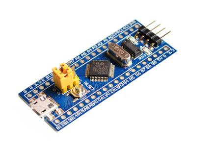
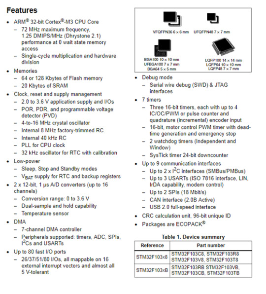
I'm not going to say much about this chip.The chip download code is j-link, as shown below:
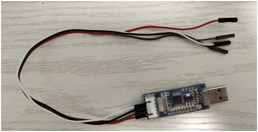
This is a simple version of j-link, only support SWD mode debugging and download, not support JTAG.But for the development of STM32 chip, SWD debugging method is enough.
Download the code to the STM32 chip
Ensure the correct wiring of j-link and STM32F103C8T6, and then the chip can be identified in the KEIL development environment:
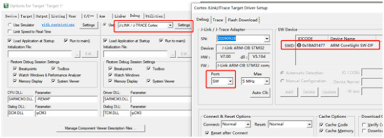
Click the download button to download the code to the chip:
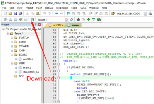
STM32 code
The buttons and text in the display screen have corresponding addresses. In this project, the addresses of the display screen components are as follows:
#define RED_COLOR 0x07
#define ICON_WHITE_ADDR 0x02
#define ICON_RED_ADDR 0x03
#define ICON_GREEN_ADDR 0x04
#define ICON_BLUE_ADDR 0x05
#define TEXT_RED_ADDR 0x07
#define TEXT_GREEN_ADDR 0x08
#define TEXT_BLUE_ADDR 0x09
#define TEXT_WHITE_ADDR 0x06
#define SWITCH_ONOFF_ADDR 0x01
#define ICON_ON 0x01
#define ICON_OFF 0x00
u8 data_send[8]= {0xA5, 0x5A, 0x05, 0x82, 0x00, 0x00, 0x00,0x00};
Data sent to the display screen should be sent according to the corresponding format:
U8 data_send[8]= {0xA5, 0x5A, 0x05, 0x82, 0x00,0x00,0x00,0x00};
Data [4]\ data[5] is the high and low order of component addresses.
Data [6]\ data[7] is the data to be displayed by the component.
The main logical code will be provided below:
#include "stm32f10x.h"
#include "usart.h"
#include "delay.h"
#include "../BOARD/ws2812/ws2812.h"
struct RGB_COLOR
{
u8 C_RED;
u8 C_GREEN;
u8 C_BLUE;
u8 C_WHITE;
u8 C_RED_FLAG;
u8 C_GREEN_FLAG;
u8 C_BLUE_FLAG;
};
#define ICON_WHITE_ADDR 0x02
#define ICON_RED_ADDR 0x03
#define ICON_GREEN_ADDR 0x04
#define ICON_BLUE_ADDR 0x05
#define TEXT_RED_ADDR 0x07
#define TEXT_GREEN_ADDR 0x08
#define TEXT_BLUE_ADDR 0x09
#define TEXT_WHITE_ADDR 0x06
#define SWITCH_ONOFF_ADDR 0x01
#define ICON_ON 0x01
#define ICON_OFF 0x00
u8 data_send[8]= {0xA5, 0x5A, 0x05, 0x82, 0x00, 0x00, 0x00,0x00};
void UART1_Send_Array(u8 send_array[],unsigned char num)
{
u8 i=0;
while(i<num)
{
USART_SendData(USART1,send_array[i]);
while( USART_GetFlagStatus(USART1,USART_FLAG_TC)!= SET);
i++;
}
}
int main(void)
{
uart_init(115200);
delay_init();
struct RGB_COLOR USER_RGB_COLOR;
USER_RGB_COLOR.C_BLUE=0;
USER_RGB_COLOR.C_GREEN=0;
USER_RGB_COLOR.C_RED=0;
USER_RGB_COLOR.C_RED_FLAG=1;
USER_RGB_COLOR.C_GREEN_FLAG=1;
USER_RGB_COLOR.C_BLUE_FLAG=1;
u16 k,q;
u8 BLINK_2=0;
u8 USER_R=0,USER_G=0,USER_B=0,COLOR_TYPE=0,COLOR_DIR=0;
u8 blink_type=0;
u16 times=0;
RGB_LED_Init();
while(1)
{
if(USART_RX_END)
{ ��
switch (USART_RX_BUF[5])
{
case 0x33:
PIXEL_NUM=USART_RX_BUF[8];
break;
case LED_ALL_ONOFF:
blink_type=0;
if(USART_RX_BUF[8]==0)
{
data_send[5]=ICON_RED_ADDR;
data_send[7]=ICON_OFF;
UART1_Send_Array(data_send,8);
data_send[5]=TEXT_RED_ADDR;
data_send[7]=0x00;
UART1_Send_Array(data_send,8);
data_send[5]=ICON_GREEN_ADDR;
data_send[7]=ICON_OFF;
UART1_Send_Array(data_send,8);
data_send[5]=TEXT_GREEN_ADDR;
data_send[7]=0x00;
UART1_Send_Array(data_send,8);
data_send[5]=ICON_BLUE_ADDR;
data_send[7]=ICON_OFF;
UART1_Send_Array(data_send,8);
data_send[5]=TEXT_BLUE_ADDR;
data_send[7]=0x00;
UART1_Send_Array(data_send,8);
USER_RGB_COLOR.C_BLUE=0;
USER_RGB_COLOR.C_GREEN=0;
USER_RGB_COLOR.C_RED=0;
data_send[5]=ICON_WHITE_ADDR;
data_send[7]=ICON_OFF;
UART1_Send_Array(data_send,8);
data_send[5]=TEXT_WHITE_ADDR;
data_send[7]=0x00;
UART1_Send_Array(data_send,8);
USER_RGB_COLOR.C_WHITE=0;
}
else
{
USER_RGB_COLOR.C_BLUE=0x32;
USER_RGB_COLOR.C_GREEN=0x10;
USER_RGB_COLOR.C_RED=0x24;
USER_RGB_COLOR.C_RED_FLAG=0;
USER_RGB_COLOR.C_GREEN_FLAG=0;
USER_RGB_COLOR.C_BLUE_FLAG=0;
data_send[5]=ICON_RED_ADDR;
data_send[7]=ICON_ON;
UART1_Send_Array(data_send,8);
data_send[5]=TEXT_RED_ADDR;
data_send[7]=0x24;
UART1_Send_Array(data_send,8);
data_send[5]=ICON_GREEN_ADDR;
data_send[7]=ICON_ON;
UART1_Send_Array(data_send,8);
data_send[5]=TEXT_GREEN_ADDR;
data_send[7]=0x10;
UART1_Send_Array(data_send,8);
data_send[5]=ICON_BLUE_ADDR;
data_send[7]=ICON_ON;
UART1_Send_Array(data_send,8);
data_send[5]=TEXT_BLUE_ADDR;
data_send[7]=0x32;
UART1_Send_Array(data_send,8);
}
RGB_LED_Write_24Bits(USER_RGB_COLOR.C_RED, USER_RGB_COLOR.C_GREEN, USER_RGB_COLOR.C_BLUE);
break;
case RED_COLOR:
blink_type=0;
if(USER_RGB_COLOR.C_RED_FLAG==1)
{
if(USART_RX_BUF[8]==0)
break;
}
data_send[5]=ICON_WHITE_ADDR;
data_send[7]=ICON_OFF;
UART1_Send_Array(data_send,8);
data_send[5]=TEXT_WHITE_ADDR;
data_send[7]=0x00;
UART1_Send_Array(data_send,8);
USER_RGB_COLOR.C_WHITE=0;
data_send[5]=SWITCH_ONOFF_ADDR;
data_send[7]=ICON_ON;
UART1_Send_Array(data_send,8);
data_send[5]=ICON_RED_ADDR;
if(USART_RX_BUF[8]>0)data_send[7]=ICON_ON;
else data_send[7]=ICON_OFF;
UART1_Send_Array(data_send,8);
USER_RGB_COLOR.C_RED=USART_RX_BUF[8];
USER_RGB_COLOR.C_RED_FLAG=0;
if(USER_RGB_COLOR.C_RED==0)USER_RGB_COLOR.C_RED_FLAG=1;
if((USER_RGB_COLOR.C_RED==0x00)&&(USER_RGB_COLOR.C_GREEN==0x00)&&(USER_RGB_COLOR.C_BLUE==0x00)&&(USER_RGB_COLOR.C_WHITE==0x00))
{
data_send[5]=SWITCH_ONOFF_ADDR;
data_send[7]=ICON_OFF;
UART1_Send_Array(data_send,8);
}
RGB_LED_Write_24Bits(USER_RGB_COLOR.C_RED, USER_RGB_COLOR.C_GREEN, USER_RGB_COLOR.C_BLUE); // Red
break;
case GREEN_COLOR:
blink_type=0;
if(USER_RGB_COLOR.C_GREEN_FLAG==1)
{
if(USART_RX_BUF[8]==0)
break;
}
data_send[5]=ICON_GREEN_ADDR;
if(USART_RX_BUF[8]>0)data_send[7]=ICON_ON;
else data_send[7]=ICON_OFF;
UART1_Send_Array(data_send,8);
data_send[5]=ICON_WHITE_ADDR;
data_send[7]=ICON_OFF;
UART1_Send_Array(data_send,8);
data_send[5]=TEXT_WHITE_ADDR;
data_send[7]=0x00;
UART1_Send_Array(data_send,8);
USER_RGB_COLOR.C_WHITE=0;
data_send[5]=SWITCH_ONOFF_ADDR;
data_send[7]=ICON_ON;
UART1_Send_Array(data_send,8);
USER_RGB_COLOR.C_GREEN=USART_RX_BUF[8];
USER_RGB_COLOR.C_GREEN_FLAG=0;
if(USER_RGB_COLOR.C_GREEN==0)USER_RGB_COLOR.C_GREEN_FLAG=1;
if((USER_RGB_COLOR.C_RED==0x00)&&(USER_RGB_COLOR.C_GREEN==0x00)&&(USER_RGB_COLOR.C_BLUE==0x00)&&(USER_RGB_COLOR.C_WHITE==0x00))
{
data_send[5]=SWITCH_ONOFF_ADDR;
data_send[7]=ICON_OFF;
UART1_Send_Array(data_send,8);
}
RGB_LED_Write_24Bits(USER_RGB_COLOR.C_RED, USER_RGB_COLOR.C_GREEN, USER_RGB_COLOR.C_BLUE); // Green
break;
case BLUE_COLOR:
blink_type=0;
if(USER_RGB_COLOR.C_BLUE_FLAG==1)
{
if(USART_RX_BUF[8]==0)
break;
}
data_send[5]=ICON_BLUE_ADDR;
if(USART_RX_BUF[8]>0)data_send[7]=ICON_ON;
else data_send[7]=ICON_OFF;
UART1_Send_Array(data_send,8);
data_send[5]=ICON_WHITE_ADDR;
data_send[7]=ICON_OFF;
UART1_Send_Array(data_send,8);
data_send[5]=TEXT_WHITE_ADDR;
data_send[7]=0x00;
UART1_Send_Array(data_send,8);
USER_RGB_COLOR.C_WHITE=0;
data_send[5]=SWITCH_ONOFF_ADDR;
data_send[7]=ICON_ON;
UART1_Send_Array(data_send,8);
USER_RGB_COLOR.C_BLUE=USART_RX_BUF[8];
USER_RGB_COLOR.C_BLUE_FLAG=0;
if(USER_RGB_COLOR.C_BLUE==0)USER_RGB_COLOR.C_BLUE_FLAG=1;
if((USER_RGB_COLOR.C_RED==0x00)&&(USER_RGB_COLOR.C_GREEN==0x00)&&(USER_RGB_COLOR.C_BLUE==0x00)&&(USER_RGB_COLOR.C_WHITE==0x00))
{
data_send[5]=SWITCH_ONOFF_ADDR;
data_send[7]=ICON_OFF;
UART1_Send_Array(data_send,8);
}
RGB_LED_Write_24Bits(USER_RGB_COLOR.C_RED, USER_RGB_COLOR.C_GREEN, USER_RGB_COLOR.C_BLUE); // Blue
break;
case WHITE_COLOR:
blink_type=0;
data_send[5]=ICON_WHITE_ADDR;
if(USART_RX_BUF[8]>0)data_send[7]=ICON_ON;
else data_send[7]=ICON_OFF;
UART1_Send_Array(data_send,8);
data_send[5]=ICON_RED_ADDR;
data_send[7]=ICON_OFF;
UART1_Send_Array(data_send,8);
data_send[5]=TEXT_RED_ADDR;
data_send[7]=0x00;
UART1_Send_Array(data_send,8);
data_send[5]=ICON_GREEN_ADDR;
data_send[7]=ICON_OFF;
UART1_Send_Array(data_send,8);
data_send[5]=TEXT_GREEN_ADDR;
data_send[7]=0x00;
UART1_Send_Array(data_send,8);
data_send[5]=ICON_BLUE_ADDR;
data_send[7]=ICON_OFF;
UART1_Send_Array(data_send,8);
data_send[5]=TEXT_BLUE_ADDR;
data_send[7]=0x00;
UART1_Send_Array(data_send,8);
USER_RGB_COLOR.C_BLUE=0;
USER_RGB_COLOR.C_GREEN=0;
USER_RGB_COLOR.C_RED=0;
USER_RGB_COLOR.C_RED_FLAG=1;
USER_RGB_COLOR.C_GREEN_FLAG=1;
USER_RGB_COLOR.C_BLUE_FLAG=1;
data_send[5]=SWITCH_ONOFF_ADDR;
data_send[7]=ICON_ON;
UART1_Send_Array(data_send,8);
USER_RGB_COLOR.C_WHITE=USART_RX_BUF[8];
if((USER_RGB_COLOR.C_RED==0x00)&&(USER_RGB_COLOR.C_GREEN==0x00)&&(USER_RGB_COLOR.C_BLUE==0x00)&&(USER_RGB_COLOR.C_WHITE==0x00))
{
data_send[5]=SWITCH_ONOFF_ADDR;
data_send[7]=ICON_OFF;
UART1_Send_Array(data_send,8);
}
RGB_LED_Write_24Bits(USER_RGB_COLOR.C_WHITE, USER_RGB_COLOR.C_WHITE, USER_RGB_COLOR.C_WHITE);
break;
case BLINK1:
blink_type=1;
data_send[5]=ICON_RED_ADDR;
data_send[7]=ICON_OFF;
UART1_Send_Array(data_send,8);
data_send[5]=TEXT_RED_ADDR;
data_send[7]=0x00;
UART1_Send_Array(data_send,8);
data_send[5]=ICON_GREEN_ADDR;
data_send[7]=ICON_OFF;
UART1_Send_Array(data_send,8);
data_send[5]=TEXT_GREEN_ADDR;
data_send[7]=0x00;
UART1_Send_Array(data_send,8);
data_send[5]=ICON_BLUE_ADDR;
�� data_send[7]=ICON_OFF;
UART1_Send_Array(data_send,8);
data_send[5]=TEXT_BLUE_ADDR;
data_send[7]=0x00;
UART1_Send_Array(data_send,8);
USER_RGB_COLOR.C_BLUE=0;
USER_RGB_COLOR.C_GREEN=0;
USER_RGB_COLOR.C_RED=0;
data_send[5]=ICON_WHITE_ADDR;
data_send[7]=ICON_OFF;
UART1_Send_Array(data_send,8);
data_send[5]=TEXT_WHITE_ADDR;
data_send[7]=0x00;
UART1_Send_Array(data_send,8);
USER_RGB_COLOR.C_WHITE=0;
data_send[5]=SWITCH_ONOFF_ADDR;
data_send[7]=ICON_ON;
UART1_Send_Array(data_send,8);
break;
case BLINK2:
blink_type=2;
data_send[5]=ICON_RED_ADDR;
data_send[7]=ICON_OFF;
UART1_Send_Array(data_send,8);
data_send[5]=TEXT_RED_ADDR;
data_send[7]=0x00;
UART1_Send_Array(data_send,8);
data_send[5]=ICON_GREEN_ADDR;
data_send[7]=ICON_OFF;
UART1_Send_Array(data_send,8);
data_send[5]=TEXT_GREEN_ADDR;
data_send[7]=0x00;
UART1_Send_Array(data_send,8);
data_send[5]=ICON_BLUE_ADDR;
data_send[7]=ICON_OFF;
UART1_Send_Array(data_send,8);
data_send[5]=TEXT_BLUE_ADDR;
data_send[7]=0x00;
UART1_Send_Array(data_send,8);
USER_RGB_COLOR.C_BLUE=0;
USER_RGB_COLOR.C_GREEN=0;
USER_RGB_COLOR.C_RED=0;
data_send[5]=ICON_WHITE_ADDR;
data_send[7]=ICON_OFF;
UART1_Send_Array(data_send,8);
data_send[5]=TEXT_WHITE_ADDR;
data_send[7]=0x00;
UART1_Send_Array(data_send,8);
USER_RGB_COLOR.C_WHITE=0;
data_send[5]=SWITCH_ONOFF_ADDR;
data_send[7]=ICON_ON;
UART1_Send_Array(data_send,8);
break;
case BLINK3:
blink_type=3;
data_send[5]=ICON_RED_ADDR;
data_send[7]=ICON_OFF;
UART1_Send_Array(data_send,8);
data_send[5]=TEXT_RED_ADDR;
data_send[7]=0x00;
UART1_Send_Array(data_send,8);
data_send[5]=ICON_GREEN_ADDR;
data_send[7]=ICON_OFF;
UART1_Send_Array(data_send,8);
data_send[5]=TEXT_GREEN_ADDR;
data_send[7]=0x00;
UART1_Send_Array(data_send,8);
data_send[5]=ICON_BLUE_ADDR;
data_send[7]=ICON_OFF;
UART1_Send_Array(data_send,8);
data_send[5]=TEXT_BLUE_ADDR;
data_send[7]=0x00;
UART1_Send_Array(data_send,8);
USER_RGB_COLOR.C_BLUE=0;
USER_RGB_COLOR.C_GREEN=0;
USER_RGB_COLOR.C_RED=0;
// USER_RGB_COLOR.C_RED_FLAG=1;
// USER_RGB_COLOR.C_GREEN_FLAG=1;
// USER_RGB_COLOR.C_BLUE_FLAG=1;
data_send[5]=ICON_WHITE_ADDR;
data_send[7]=ICON_OFF;
UART1_Send_Array(data_send,8);
data_send[5]=TEXT_WHITE_ADDR;
data_send[7]=0x00;
UART1_Send_Array(data_send,8);
USER_RGB_COLOR.C_WHITE=0;
data_send[5]=SWITCH_ONOFF_ADDR;
data_send[7]=ICON_ON;
UART1_Send_Array(data_send,8);
break;
case BLINK4:
blink_type=4;
data_send[5]=ICON_RED_ADDR;
data_send[7]=ICON_OFF;
UART1_Send_Array(data_send,8);
data_send[5]=TEXT_RED_ADDR;
data_send[7]=0x00;
UART1_Send_Array(data_send,8);
data_send[5]=ICON_GREEN_ADDR;
data_send[7]=ICON_OFF;
UART1_Send_Array(data_send,8);
data_send[5]=TEXT_GREEN_ADDR;
data_send[7]=0x00;
UART1_Send_Array(data_send,8);
data_send[5]=ICON_BLUE_ADDR;
data_send[7]=ICON_OFF;
UART1_Send_Array(data_send,8);
data_send[5]=TEXT_BLUE_ADDR;
data_send[7]=0x00;
UART1_Send_Array(data_send,8);
USER_RGB_COLOR.C_BLUE=0;
USER_RGB_COLOR.C_GREEN=0;
USER_RGB_COLOR.C_RED=0;
data_send[5]=ICON_WHITE_ADDR;
data_send[7]=ICON_OFF;
UART1_Send_Array(data_send,8);
data_send[5]=TEXT_WHITE_ADDR;
data_send[7]=0x00;
UART1_Send_Array(data_send,8);
USER_RGB_COLOR.C_WHITE=0;
data_send[5]=SWITCH_ONOFF_ADDR;
data_send[7]=ICON_ON;
UART1_Send_Array(data_send,8);
break;
default:
USART_RX_END=0;
USART_RX_STA=0;
break;
}
USART_RX_STA=0;
USART_RX_END=0;
}
else
{
if(blink_type==1)
{
times++;
if(times>=14)
{
times=0;
if(COLOR_DIR==0)
{
if(COLOR_TYPE==0)
{
USER_R++;
USER_G=0;
USER_B=0;
}
else if(COLOR_TYPE==1)
{
USER_R=0;
USER_G++;
USER_B=0;
}
else if(COLOR_TYPE==2)
{
USER_R=0;
USER_G=0;
USER_B++;
}
else if(COLOR_TYPE==3)
{
USER_R++;
USER_G++;
USER_B=0;
}
else if(COLOR_TYPE==4)
{
USER_R=0;
USER_G++;
USER_B++;
}
else if(COLOR_TYPE==5)
{
USER_R++;
USER_G=0;
USER_B++;
}
if((USER_R>=250)||(USER_G>=250)||(USER_B>=250))
{
COLOR_DIR=1;
}
}
else
{
if(COLOR_TYPE==0)
{
USER_R--;
USER_G=0;
USER_B=0;
}
else if(COLOR_TYPE==1)
{
USER_R=0;
USER_G--;
USER_B=0;
}
else if(COLOR_TYPE==2)
{
USER_R=0;
USER_G=0;
USER_B--;
}
else if(COLOR_TYPE==3)
{
USER_R--;
USER_G--;
USER_B=0;
}
else if(COLOR_TYPE==4)
{
USER_R=0;
USER_G--;
USER_B--;
}
else if(COLOR_TYPE==5)
{
USER_R--;
USER_G=0;
USER_B--;
}
if((USER_R==0x02)||(USER_G==0x02)||(USER_B==0x02))
{
COLOR_DIR=0;
COLOR_TYPE++;
if(COLOR_TYPE>5)
COLOR_TYPE=0;
}
}
RGB_LED_Write_24Bits(USER_R,USER_G,USER_B);
}
delay_ms(1);
}
else if(blink_type==2)
{
k++;
if(k>=150)
{
k=0;
q=200;
{
BLINK_2++;
if(BLINK_2>8)BLINK_2=0;
}
if(BLINK_2==0)
RGB_LED_Write_24Bits(q,0,0);
else if(BLINK_2==1)
RGB_LED_Write_24Bits(0,q,0);
else if(BLINK_2==2)
RGB_LED_Write_24Bits(0,0,q);
else if(BLINK_2==3)
RGB_LED_Write_24Bits(q,q,0);
else if(BLINK_2==4)
RGB_LED_Write_24Bits(0,q,q);
else if(BLINK_2==5)
RGB_LED_Write_24Bits(q,0,q);
else if(BLINK_2==6)
RGB_LED_Write_24Bits(q-100,q,0);
else if(BLINK_2==7)
RGB_LED_Write_24Bits(0,q-80,q);
else if(BLINK_2==8)
RGB_LED_Write_24Bits(q,0,q-120);
else if(BLINK_2==9)
RGB_LED_Write_24Bits(40,q-100,q-70);
else if(BLINK_2==10)
RGB_LED_Write_24Bits(q,100,q-80);
}
delay_ms(1);
}
else if(blink_type==3)
{
k++;
if(k>=1000)
{
k=0;
{
BLINK_2++;
if(BLINK_2>5)BLINK_2=0;
}
{
if(BLINK_2==0)
RGB_LED_Write_24Bits(q,0,0);
else if(BLINK_2==1)
RGB_LED_Write_24Bits(0,q,0);
else if(BLINK_2==2)
RGB_LED_Write_24Bits(0,0,q);
else if(BLINK_2==3)
RGB_LED_Write_24Bits(q,q,0);
else if(BLINK_2==4)
RGB_LED_Write_24Bits(0,q,q);
else if(BLINK_2==5)
RGB_LED_Write_24Bits(q,0,q);
}
}
delay_ms(1);
}
else if(blink_type==4)
{
k++;
if(k>=500)
{
k=0;
q=0;
BLINK_2++;
if(BLINK_2>5)BLINK_2=0;
}
q++;
if(q>=250)q=0;
if(BLINK_2==0)
RGB_LED_Write_24Bits(q,0,0);
else if(BLINK_2==1)
RGB_LED_Write_24Bits(0,q,0);
else if(BLINK_2==2)
RGB_LED_Write_24Bits(0,0,q);
else if(BLINK_2==3)
RGB_LED_Write_24Bits(q,q,0);
else if(BLINK_2==4)
RGB_LED_Write_24Bits(0,q,q);
else if(BLINK_2==5)
RGB_LED_Write_24Bits(q,0,q);
delay_ms(1);
}
else
{
}
}
}
}
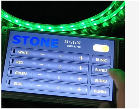
Finally, the code is downloaded into the STM32 chip, and the completed circuit board is connected to the display screen, and the power supply is guaranteed to be stable. Then the brightness and color of the RGB lamp can be controlled through the STONE display module.
The final hardware connection diagram
Running effect

0 notes
Photo

#Professional_Resume_design #CV #red_colored #Minimal #Fiverr_order #Graphics_design
0 notes
Photo

吾妻橋と屋形船 reflection and halation #夜景 #night_view #屋形船 #coverd_boat #Azumabashi_bridge #隅田川 #sumida_river #赤色 #red_color #blue_color #水面 #駒形橋 #komagatabashi_bridge #sony #xperia https://www.instagram.com/p/Cmay84KrJ6u/?igshid=NGJjMDIxMWI=
#夜景#night_view#屋形船#coverd_boat#azumabashi_bridge#隅田川#sumida_river#赤色#red_color#blue_color#水面#駒形橋#komagatabashi_bridge#sony#xperia
0 notes
Photo

夜に赤く Red_color #night_view #植え込み #red&black #植物 #plant #sony #xperia https://www.instagram.com/p/CmGKL2ardYT/?igshid=NGJjMDIxMWI=
0 notes
Photo

光の競演 Light Competition #夜景 #night_view #すみだリバーウォーク #Sumida_River_Walk #隅田川 #Sumida_River #赤 #red_color #青 #blue_color #金 #gold_color #映り込み #リフレクション #reflection #反射 #ハレーション #halation #明かり #灯り #屋形船 #coverd_boat #sony #xperia https://www.instagram.com/p/Cma_HvcLT5D/?igshid=NGJjMDIxMWI=
#夜景#night_view#すみだリバーウォーク#sumida_river_walk#隅田川#sumida_river#赤#red_color#青#blue_color#金#gold_color#映り込み#リフレクション#reflection#反射#ハレーション#halation#明かり#灯り#屋形船#coverd_boat#sony#xperia
1 note
·
View note