#lm358
Explore tagged Tumblr posts
Photo
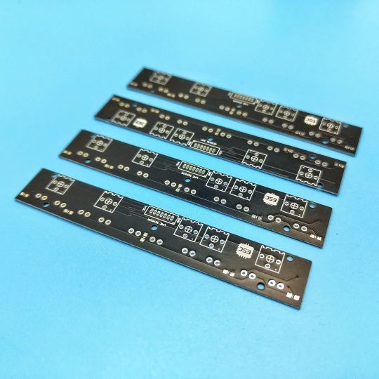
I MADE A custom line sensor array for my line follower robot. It has 5 IR CHANNELS individual sensing adjustment LED indication @jlcpcb #linefollowerrobot #linefollower #ir #irsensor #irmodule #qtr #pololu #robotics #pcb #electronics #makers #lm358 #opamp #led https://www.instagram.com/p/Cpm_HwsrfT3/?igshid=NGJjMDIxMWI=
#linefollowerrobot#linefollower#ir#irsensor#irmodule#qtr#pololu#robotics#pcb#electronics#makers#lm358#opamp#led
1 note
·
View note
Video
youtube
LED Fader Using 555 Timer IC
Wanted to generate a LED fading effect (fade-in and fade-out) for my upcoming video tutorial using the 555 timer IC.I already have a video where I used LM358 Dual Operational Amplifier IC and another one with Arduino to generate the LED fading effect. YouTube, is full of video showing how to generate the fading effect using 555 timer IC. However, none of them produce a true fading effect. Some just fades-in but never fades-out. And there is literally no explanation of how they are generating the fading effect other than just showing how to assemble the components. In this tutorial, I am going to show you guys how to create a true LED fading effect using the 555 timer IC. I will also explain how the circuit works and how changing components change the fading effect of the LEDs.
2 notes
·
View notes
Text
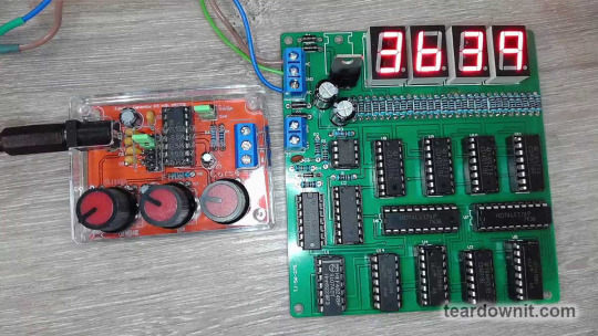
DAC0832 Digital-to-Analog Converter
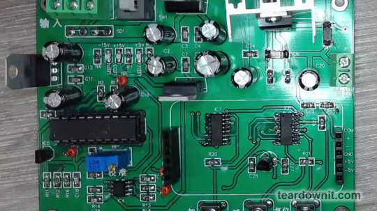
Digital-to-analog converters (DACs) are often built into microcontrollers but tend to be slow, noisy, and lack resolution. So, we frequently use specialized DAC chips.
Today's example is a digitally controlled voltage regulator module that could be used in a lab power supply. The workhorse here is the LM317T chip, which has the DAC0832 digital-to-analog converter at its core.
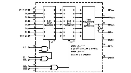
The DAC0832 is a pretty advanced chip, with not one but two latches arranged in sequence. This setup allows it to store digital data from the microprocessor bus and convert it to an analog value at just the right moment.
In the post about the 74HC374 latch, we used it to freeze the readings on seven-segment displays for a second while counting input pulses.
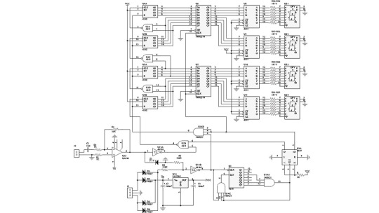
After a second, the data from the counters was sent out to the display decoders, showing the frequency of the input signal measured a second earlier. Meanwhile, the next count of pulses was happening. This made for a good frequency counter.
Each of the two latches in the DAC0832 can be made transparent, meaning asynchronous. In this mode, data from the input instantly appears in the output.

A logic high on the ¬LE (¬LATCH ENABLE) pin is needed to set the input latch to transparent asynchronous mode. You could call it LATCH DISABLE without the ¬ sign.
¬LE = ILE & (¬¬CS & ¬¬WR1) = ILE & ¬(¬CS | ¬WR1).
In simpler terms, you need a logic high on the ILE (INPUT LATCH ENABLE) input and a logic low on at least one of the two inputs, ¬CS (¬CHIP SELECT) or ¬WR1 (¬WRITE1). The ¬WRITE1 and ¬WRITE2 inputs are used for strobe signals.
For the 8-bit DAC latch register, the logic for ¬LATCH ENABLE is more straightforward:
¬LE = ¬¬XFER & ¬¬WR2 = ¬(¬XFER | ¬WR2).
So, you need a low logic level on at least one of the inputs: ¬XFER (¬TRANSFER) or ¬WR2 (¬WRITE2).
The heart of the DAC0832 is the analog-to-digital converter. This analog multiplexer switches precision silicon-chromium resistors deposited on a silicon chip.
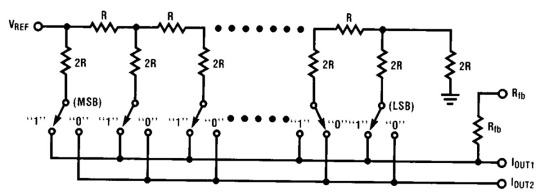
This manufacturing technique ensures high accuracy and temperature stability, which is why we use DAC chips in our favorite high-fidelity audio gear.
Plus, a multiplexer can work much faster than pulse-width modulation (PWM) analog-to-digital conversion, which we often use in Arduino DIY projects.
Also, PWM produces square pulses with different duty cycles with a broad frequency spectrum. The frequencies might be inaudible, but their interference with other frequencies in the device can create audible noises, which can be pretty unpleasant.
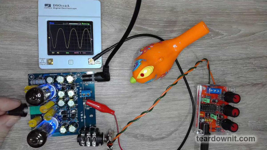
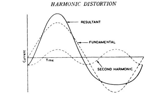
The homemade tube amplifier article mentioned that asymmetrical and softly clipped waveforms sound pleasant and musical to human ears because they're full of even harmonics.
But a square, symmetrical waveform has many odd harmonics, which aren't so nice to listen to, especially when they create dissonance with the overtones of other sounds played at the same time.
The DAC0832 needs an external operational amplifier to convert the current through switched precision resistors into an output voltage.
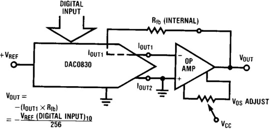
We'd probably go with the NE5532 for audio output, which we used for a simple, affordable, and high-quality headphone amp.

But the good old LM358 will do fine for a power supply. Here, op-amp IC4A converts the output current of the DAC0832 into voltage, and IC4B amplifies the resulting signal by six times.
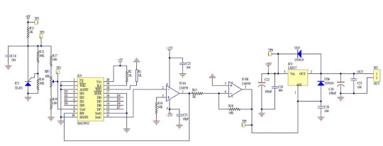
The TL431 chip generates the DAC0832's reference voltage, which is adjusted with the potentiometer RP1. The voltage ranges from 5×1100/1200=0.42V to 4.58V.
The output of IC4B is connected to the adjustment input of the LM317. Therefore, this chip's output voltage, and therefore our homemade power supply's, will be 1.25 volts higher than IC4B's.
So, the output voltage formula is:
Vout = 1.25 + 6 * Vref * DIGITAL INPUT / 256 = 1.25 + 0.024 * Vref * DIGITAL INPUT.
Adjusting the reference voltage can change the increment and decrement steps when pressing the corresponding buttons on the power supply's front panel.
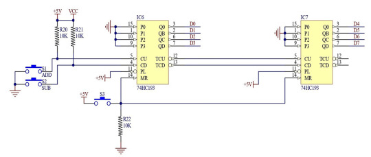
The digital value for converting to a voltage is set by two 74HC193 four-bit up/down counters.
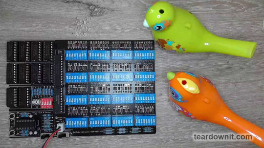
These are presettable counters, similar to the ones we used as registers in our DIY 4-bit CPU.
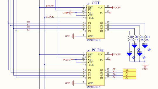
Each CPU's four registers used one SN74HC161L chip as a latch. The increment function was only used in the program counter (PC) register. The other three registers disabled it by grounding the CEP and CET control inputs.
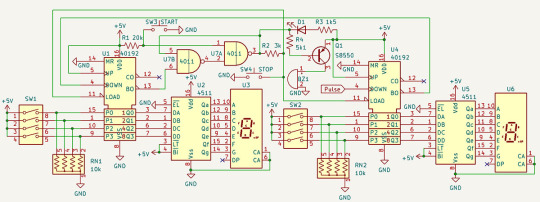
We used the decrement function in a countdown timer that could be set to any number of seconds from 0 to 99.
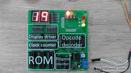
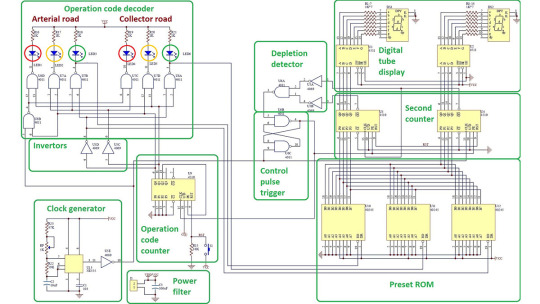
Thanks to the preset function, the chosen value from the PRESET ROM of our electronic traffic light tells the second counter how long the current signal combination should last. The decrement function was also used there.
In today's power supply, we do not use the preset function but both increment and decrement counting. There's also a reset button to set both counters to zero.

Accordingly, the digital-to-analog converter will also be set to zero since both of its internal latches are permanently in transparent asynchronous mode.
To lock the chip in this mode, the ¬CS, ¬WR1, ¬WR2, and ¬XFER control inputs are soldered to ground.

We could make a power supply with non-volatile preset memory if we used a microcontroller instead of up/down counters. The microcontroller's analog-to-digital converter could be used for the voltmeter and ammeter.
And if the microcontroller doesn't have enough pins to connect the 8-bit DAC data bus, we could use a shift register for serial data transfer.
In this case, the DAC0832's latch registers could be very handy if the shift register doesn't have a built-in latch.
After all, to convert a binary number into a voltage, you must wait until the binary number is fully received from the microcontroller via the serial bus. Otherwise, you’d get meaningless voltage jumps, which are unacceptable in a power supply.
0 notes
Text
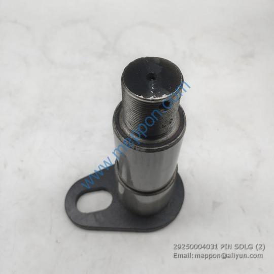
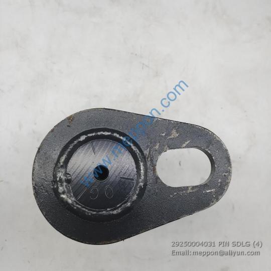
29250004031 PIN SDLG
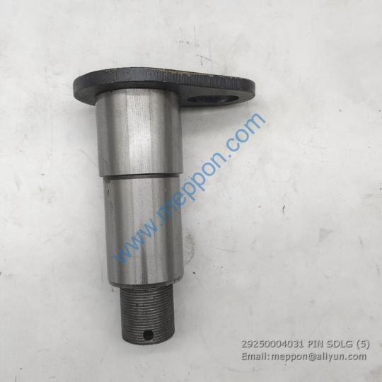
29250004031 PIN SDLG

28150005211 车架线��� 4110001126096 排气接管612600113590 6900016258 组合仪表盘SDLG-1G 29340030651 液压油箱总成 6233000254 PLATE 29290031421 钢管 29260013491 液压油箱 A3-2903000967 推拉杆总成 6900001558 塑料护罩 6222000009 保险丝ATS5 26141016571 软管LGB126-003062 6410007364 固定座 FLG1.3 停用-机油滤清器壳体总成 LGM086HWB01 ISOLATION 26330019181 上盖板 29310016061 快换开关CVV-00007361 4110000186620 中冷出气胶管 6900019383 机罩电气总成 29330017941 轮边减速器 LG2834000331 连接盘13494349 29030046291 钢管4×40×40×4320 14531124 回转支承83齿/36-36 4110000561272 B型轴套 φ60*φ70*30 4110000734011 制动缸体 4110001654034 法兰盘380399 4190015408 后车架 LG9150000185 挡圈GB893.1-86-80 29020019521 停用-马达 1690200142 LOWER GIRDER 26430000072 电池 LR20(XJ) 1.5V 水银/松下 7100001111 护网总成 4120006307002 蜂鸣器安装板 K3-2928000651 铲斗 E2-2050900027 侧减震垫A00435SDA 29260031331 105后车架自检记录 28270002071 软管LGB128-412250 4120010883001 胶管F781C90C202012-1850-PG750 6900005968 车体板-20 28809031781 六角头螺栓90003802627 29290041722 圆形密封圈3754631-52D 2010900253 驾驶室总成 29120204691 制动助力器2-32*35 4110000415105 三角形壳体08000F-S675 4180000297 踏板焊接(金色) 4110003847039 停用-LG93X铲斗(1.6m3) 29090012291 切削刃II 29440000711 E6225F铲斗 3030900126 压板 11215748 热继电器 29140022081 活塞环 4120004276 固定板 6264000593 转斗缸活塞杆 4120005893 仪表台线束 FLGZJ1B 发动机左前支架 29310016911 停用-前进低档离合器壳体BD05-01200 11418548 固定板 28220002851 液压油箱防滑板(金色) 29270023001 上支架 11221209 E665F液压挖掘机 29260021561 后车架电气总成 4130000432 P轴承GB276-6208N 28230020871 板 4120016161 连杆 6222000299 法兰盖 11218492 电磁阀总成 4110001007002 后油封1000686214 28100011491 溢流阀LG6300E 28350003311 液压油箱总成 7600311111900 吸油钢管 LG4019000075 大臂油封 F31Q6-02600 垫圈GB97.1-18EpZn-300HV B631000075 左转斗油缸HSGL-70*45*802-1087 4110001058063 轴套 29170140781 垫片 4110000081107 轴承 6412 29130011811 盖板焊合 LG2905001468201 气缸床 4110000129345 加强板 4041003239 垫圈 29150004241 防尘网-水散 6264000384 停用-管3214514473 4110000081255 高压内六角M6*30 4110001952080 钢珠07715-01605 LG2990000026 压装胎类工装维护点检卡 4110000970237 密封圈1118693-84D 11219761 953N 5111000798 HATCH 29171003151 DECAL 26441010111 仪表台线束 4110000147 板 4190002433 空气滤清器J80G5-1109100B 11225217 刀片CNMG160612E-R 6605(普拉米特) 6900021795 气弹簧 28020006711 转斗缸小腔软管 26441002491 直角法兰接头1CFL9-36-16 29260009111 转斗油缸HSGF-190*100*545-1085 5602113GA9 拉杆支板 4110002654030 PLATE_RR -RH 4120005023007 散热器总成 29010021871 工作装置附件 4110001019005 燃油管组件16809-42500 28010011391 工具箱总成 9150000438 活塞包 29130018971 调整垫-喷油泵F0211 3025 EZ 0130 17 21909004621 支架 6264000440 LGB680(先导型)驾驶室台架总成 A2-2902001003 吊耳 29031011801 LGS812H液压油箱总成 14734705 丝座M8*16*88 29190010341 P挡圈GB893.1-38-65Mn 26300002171 驾驶室附件 26120001671 P-螺栓GB5786-M20*1.5*70EpZn-10.9 26010008831 销 29100011071 行星齿轮 26290007941 筋板 C24-4110002230 斗齿销垫 29370008601 活塞杆24A612930 4120006268030 发动机罩 FKCSQ3502432KG01 弹垫 4019000034 钢板t35-SM490A 26020010101 单组份聚氨酯密封胶 回天8921U 600ml/支 L0200Y3224A23T2 喷嘴盘C1391B 11214726 恒联电茶炉 12KW 29250008011 龙工660-门下玻璃 60070011AT200 风扇皮带 29420000031 DLI耳轴防尘圈Q/HL 102147-2014 DLI φ65xφ75x5 J7300001764A BOOM(WELDED) F沃尔沃240-PMB LG665E履带式液压挖掘机 29190014351 矩形管 29350010201 弹簧03.04.01.00032 29010034162 WORKING EQUIPMENT ACCESSORY 937011 支承板 21909011261 固定板 4110000555068 仪表盘支架 6390203301 铲斗总成BG20 6410004021 压冷管 29050203581 前轮驱动换上 LG5304000009 PLATE 6900008026 标准筒100 840 4041001151 气缸盖罩衬垫614040021 8285564 翻斗缸销轴 14409132 P-下叉 2810000388003 板 29140008531 驾驶室总成 2120400112 板-WT 11216536 PLATE 4041000786 支腿 26240005601 发动机总成 29110012441 变速泵垫 29380032341 密封件包24A601000S 4043000906 平衡铁 6231000096 欧式长吊环 ICH8、2.12T 11211879 燃油粗滤支架 11214418 发动机罩标识包 6399013362 GPS(河南轩辕科技) 26291005451 胶管接头JB1886-25/28Ⅰ*642 4120008223 管1E132-73350 29120034641 支架总成 4120005932013 横筋板 6392900054 U形螺栓LGB159-12535 4110000846132 放油阀 14406496 圆螺母垫圈20 01658-22016 6614000041 上部框架 11224195 全抛光两用扳手13mm 29090012281 销轴LGB326-G38.1*110*285-101G(L3=15) 29310012311 圆垫片 29390004011 附加皮带轮垫块 A8PW0-1005155 6900009507 回油滤芯 28809038661 E936驾驶室 FZ0000786 衬套126611 29010037873 护板 14403615 电磁阀C101000026 6293000052 法兰LGB114-212501A 4110004174112 阀HVSE-09-09 14408235 活塞03000P 26361000231 扭力扳手QL6N 4120000919 10款新式后尾灯 29330074131 集成块LM358 4015000010 NIPPLE_STRAIGHT PIPING 6212000549 三菱通讯板FX1N-485BD D124000061 MAIN DRIVE BEARING ASSEMBLY LG2924002452 2 筋板 F11FG-20110 发动机罩组装件(组焊、装配)自检记录 质记123号 16027594 HOSE_ASSY 26340007181 前油封座612600010928 FZ0000401 LG6220铲斗(0.92m3) 14545021 气路连接胶管1002563433 LG29310016251C 上架JU6210 4110001058104 锥形瓶 250ml LG5111000912 盘 29141008811 LG946L发动机罩发动机罩总成 29260054302 主安全阀LG2303-A 4110001867548 下壳体总成GK19-5.0-50-100 11222513 开关总成(带导线、端子)LGCB6770002 26090004571 连接器 00960148 六角法兰面螺栓C4997265 29330089031 左控制杆 7100001182 后车架 26170044581 P-螺栓GB16674-M20*40EpZn-8.8 26260006451 驾驶室936T 28140013701 雨刮器马达 4120007884 FRONT BEAM 29370020761 右盖板 ZJ4110001273 钢管 2023000059 下机械密封200YW300-13 26050000801 废气引射器部件S00029728 LG2909000101100 多楔带10PK1500 FZ0000631 胶管F462CACE121206-1400 4043003303 脚踏阀 26330010001 变矩器壳体 16039927 前窗框架 14744745 压冷管 4110000194001 方丝座 14400312 圆柱销05012-00614 4120006922 六角头螺栓GB/T5783-M5×16 26320004061 后车架电气总成 29110013571 履带挖掘机通用铭牌 4120006410 固定后窗棂总成 2080900373 非公路自卸车 29030008221 套筒63825023 6233000454 液压油箱总成 4110000127017 梅花批头T30 世达59347 6410005118 销轴LGB301-110*168*340-1200Y E080FM3481AT9H0 硬盘转接器USB 11217982 UPPER FRAME 26290004861 交流接触器 4110000714 胶管FH621CACF151508-1230 4120018290 二组合吊带 3T*1m 4110000907159 叉尖 3120901476 铜球阀 3/8 LG20109001211 回油管 9150000454 驾驶室 29220015831 驾驶室总成(金色金属漆) 29171013921 电磁制动器T3524 26340005491 护板 28430000411 销轴GB882-B6*22EpZn-35 11212393 轮毂 Read the full article
0 notes
Video
Breathing Lights circuit. It Works! LM358
Alex's Dad told us Alex seemed to enjoy assembling our kits.
The 1st time we know Alex was last year in May. He began to try our Metal detector with the help of his father.
Congrats! He could do better and better now!
1 note
·
View note
Video
youtube
This is simple sensor kit to drive 8 active or passive sensors and log it's data into remote Android application. This system also have an option to activate external device(s) based on specified threshold of sensor data. This sensor controller is mainly build around Raspberry Pi Model 3 B+ and PIC16F877A MCU. PIC16F877A MCU is used to interface/select sensors and it's built-in 10bit multi channel ADC is used to capture the analog signals from sensors.
All the schematics and source codes of this project are available to clone at https://github.com/dilshan/android-datalogger.
1 note
·
View note
Photo

IC's logic gates and their internal view Two input logic gates AND-7408 OR-7432 NAND-7400 NOR-7486 XNOR-747266 Follow for more information posts @electronics_curiosities @electronics_curiosities @electronics_curiosities @electronics_curiosities @electronics_curiosities LIKE 👍 SHARE COMMENT 👈 #electronicscuriosities #electronicspoint #electronics #volts #amplifier #electrical #voltageregulator #audioamplifier #embeddedsystems #electronicsengineering #mechatronic #vlsi #hdl #electricalengineer #electronicsstore #ic741 #lm358 #electricalengineeringstudent #electroniclovers #ic555 #ic #circuitdesign #circuits #transistor #capacitor #resistor #current #gates (at India) https://www.instagram.com/p/CFbObfdAgYQ/?igshid=a61idg219b63
#electronicscuriosities#electronicspoint#electronics#volts#amplifier#electrical#voltageregulator#audioamplifier#embeddedsystems#electronicsengineering#mechatronic#vlsi#hdl#electricalengineer#electronicsstore#ic741#lm358#electricalengineeringstudent#electroniclovers#ic555#ic#circuitdesign#circuits#transistor#capacitor#resistor#current#gates
0 notes
Photo

A Simple Yet Feature-Packed Programmable DC Load #DCLoad #lm358 #MCP4821 #mosfet https://t.co/95P15XDGu1 http://twitter.com/iandroideu1/status/1233437060389732352
A Simple Yet Feature-Packed Programmable DC Load #DCLoad #lm358 #MCP4821 #mosfet https://t.co/95P15XDGu1
— iAndroid.eu (@iandroideu1) February 28, 2020
0 notes
Link
Sound sensitive Lighting
1 note
·
View note
Link
Over the years, readers have often commented that microcontrollers (or more specifically, the Ardui...
0 notes
Text
[Weekly Chip Hot List] Hot Chip Top 10 is out! What models are so popular (2022.10.31-11.6) | E-energyIT
Ranking Model Brand 1 STM32F103CBT6 STMicroelectronics 2 LM358 TI 3 TJA1044T/1Z NXP 4 ADXL345BCCZ-RL7 ADI 5 BAT54CW,115 Nexperia 6 PIC18F4520-I/PT Microchip 7 AZ431BZ-ATRE1 Diodes 8 RS2057XC6 Runic 9 CYPC357(C-TP) OCIC 10 R60ABD1 Micradar
STM32F103CBT6 The STMicroelectronics STM32F103CBT6 is a mainstream enhanced Arm® Cortex-M3 MCU with 128 KB Flash, 72 MHz CPU, motor control, USB and CAN.
Key applications: motor drives, application control, medical and handheld devices, PC and gaming peripherals, GPS platforms, industrial applications, PLCs, inverters, printers, scanners, alarm systems, video intercoms, HVA
LM358 The Texas Instruments LM358 is an industry standard dual op-amp. The LM358B and LM2904B devices are the next generation versions of the industry standard op-amps LM358 and LM2904 and include two high voltage (36V) op-amps. These devices offer excellent value for cost-sensitive applications with features such as low offset (300µV, typical), common mode input range to ground and high differential input voltage capability.
The LM358B and LM2904B op amps simplify circuit design with enhanced features such as unity gain stability, lower offset voltage (3mV maximum; 2mV maximum for the LM358BA and LM2904BA) and lower quiescent current (300µA per amplifier, typical). High ESD (2kV, HBM) and integrated EMI and RF filters support the use of the LM358B and LM2904B devices in more demanding and environmentally challenging applications. The LM358B and LM2904B amplifiers are available in miniature packages such as SOT23-8, as well as industry standard packages including SOIC, TSSOP and VSSOP.
Key applications: suitable for a wide range of applications
TJA1044T/1Z The NXP Semiconductors TJA1044T/1Z is part of the Mantis family of high-speed CAN transceivers. It provides the interface between the Controller Area Network (CAN) protocol controller and the physical two-wire CAN bus. The transceiver is designed for high speed CAN applications in the automotive industry and provides differential transmit and receive functionality (for microcontrollers with CAN protocol controllers).
Main application: High-speed CAN applications in the automotive industry
ADXL345BCCZ-RL7 The ADXL345BCCZ-RL7 is a small, thin, low power triaxial accelerometer that provides high resolution (13-bit) measurements of acceleration up to ±16g. The digital output data is in 16-bit binary complement format and can be accessed via SPI (3 or 4-wire) or I2C digital interfaces. the ADXL345BCCZ-RL7 is ideally suited for mobile device applications. It can measure static gravitational acceleration in tilt detection applications as well as dynamic acceleration due to motion or shock. Its high resolution (4 mg/LSB) enables measurement of tilt angle changes of less than 1.0°.
Main applications: mobile phones, medical instruments, gaming and pointing devices, industrial instrumentation, personal navigation devices, hard disk drive (HDD) protection
BAT54CW,115 The Ensysta BAT54CW,115 is a planar Schottky barrier diode with integrated protection ring for stress protection, packaged in a very small SOT323 (SC-70) surface mount device (SMD) plastic package.
Main applications: ultra-high speed switching, voltage clamping, line termination, reverse polarity protection
PIC18F4520-I/PT The PIC18F4520-I/PT is an enhanced flash microcontroller with 10-bit A/D and nanoWatt technology in the PIC18F4520 family. A range of features that can significantly reduce power consumption at runtime The PIC18F4520 devices include an internal oscillator block that generates two different clock signals, one of which can be used as a clock source for the microcontroller. This eliminates the need for an external oscillator circuit on the OSC1 or OSC2 pins.The PIC18F4520 microcontroller can be serially programmed in the end application circuit. This requires only two wires for clock and data and three additional wires for power, ground and programming voltage.
Main applications: Embedded design and development
AZ431BZ-ATRE1 The Midai AZ431BZ-ATRE1 is a three-terminal adjustable shunt regulator with guaranteed thermal stability over the entire operating range. Its sharp on-state characteristics, low temperature coefficient and low output impedance make it an ideal alternative to Zener diodes in applications such as switching power supplies, chargers and other adjustable regulators.
Main applications: chargers, voltage adapters, switching power supplies, graphics cards, precision reference voltage sources
RS2057XC6 The Runestone RS2057XC6 is a single blade double throw (SPDT) analogue switch designed to operate over a voltage range of 1.8 V to 5.5 V. The RS2057XC6 can handle both analogue and digital signals. It has a high bandwidth (300 MHz) and low on-resistance (4.5 Ω TYP).
Main applications: wearables, battery-powered devices, signal gating, chopping, modulation or demodulation (modems), portable computing, mobile phones
CYPC357(C-TP) Zuorui CYPC357(C-TP) is a small form factor SMD photocoupler device suitable for surface mount production.CYPC357(C-TP) is a photocoupler consisting of a GaAs light emitting diode and a phototransistor, which is smaller than DIP and suitable for high density surface mount applications such as programmable controllers.
Main applications: switching power supplies, smart meters, industrial controls, measuring instruments, office equipment: e.g. photocopiers, household appliances: e.g. air conditioners, fans, water heaters, etc.
R60ABD1 The R60ABD1 is a 60G millimetre wave radar module for human respiratory heart rate sensing and sleep assessment. The module is based on the FMCW radar system and is designed to report the sleep status and history of a person in a timely manner by combining long term sleep posture and body movement acquisition with the respiratory heart rate frequency output of the person in a specific situation.
The module is based on one transmitter and three receiver antennas: the wide beam radar module is mainly suitable for top-mounted mode, and can accurately scan the whole body's movement layer analysis by controlling a certain angle range through algorithms; it realises sleep detection and respiratory heart rate acquisition in different postures during human motion and static.
Main applications: sleep detection applications: sleep monitoring (history of sleep state changes), respiratory heart rate detection applications: respiratory rate monitoring, heart rate monitoring
Prepare your supply chain
Buyers of electronic components must now be prepared for future prices, extended delivery time, and continuous challenge of the supply chain. Looking forward to the future, if the price and delivery time continues to increase, the procurement of JIT may become increasingly inevitable. On the contrary, buyers may need to adopt the "just in case" business model, holding excess inventory and finished products to prevent the long -term preparation period and the supply chain interruption.
As the shortage and the interruption of the supply chain continue, communication with customers and suppliers will be essential. Regular communication with suppliers will help buyers prepare for extension of delivery time, and always understand the changing market conditions at any time. Regular communication with customers will help customers manage the expectations of potential delays, rising prices and increased delivery time. This is essential to ease the impact of this news or at least ensure that customers will not be taken attention to the sudden changes in this chaotic market.
Most importantly, buyers of electronic components must take measures to expand and improve their supplier network. In this era, managing your supply chain requires every link to work as a cohesive unit. The distributor of the agent rather than a partner cannot withstand the storm of this market. Communication and transparency are essential for management and planning. In E-energy Holding Limited, we use the following ways to hedge these market conditions for customers:
Our supplier network has been reviewed and improved for more than ten years.
Our strategic location around the world enables us to access and review the company's headquarters before making a purchase decision.
E-energy Holding Limited cooperates with a well -represented testing agency to conduct in -depth inspections and tests before delivering parts to our customers.
Our procurement is concentrated in franchise and manufacturer direct sales.
Our customer manager is committed to providing the highest level of services, communication and transparency. In addition to simply receiving orders, your customer manager will also help you develop solutions, planned inventory and delivery plans, maintain the inventory level of regular procurement, and ensure the authenticity of your parts.
Add E-energy Holding Limited to the list of suppliers approved by you, and let our team help you make strategic and wise procurement decisions.
0 notes
Text
Diptrace library right angle header

Component rotation: A feature that saves me a lot of time is a shortcut for component rotation.In the PCB Editor window, hit the N key and select Show Connections ⟶ All to show nets. The nets appear as white lines running between different pads on your PCB footprints. Show nets: One easy way to see which connections will be routed together with traces is to show nets in the PCB Editor.There are two helpful features that will help you quickly arrange components in the board as you create your PCB layout: You can start rearranging each component following the routing guidelines as best as you can until you reach a placement configuration you think will work. The initial placement of components isn’t so critical you’ll be moving them around so that you can easily route traces around the board. Arranging Componentsįrom here, you can simply drag the selection box over all the components and drag them anywhere in your circuit board space. Otherwise, you can just select everything, and your components will be placed in the lower right area of your PCB document: PCB layout with imported components. If your PCB layout currently doesn’t contain any components and you just want to import everything, simply select Execute Changes, then Close. For more complex projects, you might want to click through different groups of components to import so that you can work through different sections of your PCB layout. prjPCB. You’ll see the Engineering Change Order screen, which will allow you to select which components you want to import into the PCB layout: The Engineering Change Order screen is where you select which components to import from the schematic into your blank PCB document. After the PCB manufacturer project is saved, navigate to Design ⟶ Import Changes from. Once you’ve saved your project with the new PCB file, and there will be no other changes to your schematics, you’re ready to import your components. To turn off this option, navigate to Project ⟶ Project Options ⟶ Class Generation then unselect Generate Rooms. Note that this is not required, but it does make things easier if you don’t feel like having components grouped into rooms while creating your layout. This will get rid of the predefined red box that you’ll see after you import components into a new PCB file. Go to the Navigator panel, right-click the PCB project file, and select Add New to Project ⟶ PCB. After opening the new file, you should see a blank PCB document: A blank board in the PCB Editor window.Īt this point, I usually like to turn off the ‘automatic room generator’ option before importing components into a new PCB. Now that the schematic is finalized, you’ll want to add it to a new PCB project and create a blank PCB layout. In the image below, we’ve already added the schematic to a new PCB project, and we’re now ready to add a blank PCB into the project to get started on the layout. Our LM358 Op-amp Circuit Schematicīelow is the schematic we’ll use to get started on our PCB layout, but with one minor correction: the speaker designator has been updated to SP1. The finished version of our PCB layout will look something like this: A preview of what our final PCB layout file will look like. The component count is low enough, and the frequency range is low enough that we can place all the components on a single layer. We’ll be continuing from the end schematic of that tutorial, then walking through the process to create a finished PCB layout in Altium Designer®. This layout contains an LM358 op-amp circuit that runs at audio frequencies, as well as a number of other components. In a previous post, we focused on making a simple active amplifier using the TI LM386 op amp.

0 notes
Text
Arduino interface for TFA9842AJ Power Amplifier
TFA9842AJ is quiet old 7.5W audio power amplifier introduced by NXP. This amplifier IC is no longer produced by NXP, but still, it's available to purchase in many places, which including eBay, AliExpress, Amazon, etc.

I tested a couple of TFA9842AJ based amplifiers in the last couple of years. The main reason I liked TFA9842AJ is its simple, clean design, wide operating voltage, and high-quality bass-rich audio output. Thanks to it's built-in DC volume control circuit this audio amplifier can easily interface with MCU. In this article, we provide a generic TFA9842AJ module which works with most of Arduino boards, MCUs and SOCs.

As illustrated above, this system consists of LM321 operational amplifier and TFA9842AJ IC. To support both 5V and 3.3V logic inputs we introduce logical level selection jumper (J2) into this design. To control the volume PWM input must apply to the J1. In this system volume of the power-amplifier is proportional to the duty cycle of the PWM input. In 0% duty cycle the amplifier is in standby mode. At 100% duty cycle it performs with its maximum gain. This module is designed to work with 12V 3A DC power source. At the testing stages, we share this power source with the Arduino board.
We successfully test this module with the following development boards and MCUs:
Arduino UNO
Arduino MEGA 2560
Arduino Due
Orange Pi 3
ATmega8
ATmega328
ATmega640
In Arduino platforms, we produce PWM output using analogWrite() function. In other platforms and ICs, we generate PWM output using inbuilt hardware PWM generators.
In this design, we use SMD components to miniaturize this module. If you plan to build this using through-hole type components, use LM358 as an operational amplifier (U1).
This module is released under the terms of CC BY 4.0. The KiCad design files of this module are available to download in here.
#arduino#tfa9842aj#nxp#atmel#lm321#lm358#pwm#volume#amplifier#aud#orangepi#atmega8#atmega328#atmega640
0 notes
Photo

Op-amp IC Pins and inside view IC 741 and LM358 dual Op-amp 8 pin Dual inline packaging Ic741 An operational amplifier is a DC-coupled high-gain electronic voltage amplifier with a differential input and, usually, a single-ended output. In this configuration, an op amp produces an output potential that is typically 100,000 times larger than the potential difference between its input terminals. LM358 LM358 can be used as transducer amplifier, DC gain block etc. It has large dc voltage gain of 100dB. This IC can be operated on wide range of power supply from 3V to 32V for single power supply or from ±1.5V to ±16V for dual power supply and it also support large output voltage swing. Follow for more information posts @electronics_curiosities @electronics_curiosities @electronics_curiosities @electronics_curiosities @electronics_curiosities LIKE 👍 SHARE COMMENT 👈 #electronicscuriosities #electronicspoint #electronics #volts #amplifier #electrical #voltageregulator #audioamplifier #embeddedsystems #electronicsengineering #mechatronic #vlsi #hdl #electricalengineer #electronicsstore #ic741 #lm358 #electricalengineeringstudent #electroniclovers #ic555 #ic #circuitdesign #circuits #transistor #capacitor #resistor #current (at India) https://www.instagram.com/p/CFTnFqfhEc5/?igshid=41zkaxlwy8et
#electronicscuriosities#electronicspoint#electronics#volts#amplifier#electrical#voltageregulator#audioamplifier#embeddedsystems#electronicsengineering#mechatronic#vlsi#hdl#electricalengineer#electronicsstore#ic741#lm358#electricalengineeringstudent#electroniclovers#ic555#ic#circuitdesign#circuits#transistor#capacitor#resistor#current
0 notes
Text
input of this comparator allows a larger common
Output delay time: Including the transmission delay of the signal through the components and the rise time and fall time of the signal. Need to pay attention to the influence of different factors on the delay time when designing, including the influence of temperature, capacitive load, input overdrive, and so on.3ns. Drain-source voltage: Because the comparator has only two different output states (zero level or power supply voltage), and the output stage with full power swing characteristics is an emitter follower, which makes its input and output signal. When the potential level of the low-level signal is lower than a certain predetermined value VL, it is equivalent to the negative saturation output of the comparator circuit. The maximum bias current of the MAX917 series of comparators is only 2nA. Bias current (Ibias) is defined as the median of the input currents of the two comparators and is used to measure the effect of input impedance. The two inputs of the comparator are analog signals, and the output is a binary signal 0 or 1.
For high-speed comparators, such as MAX961, the typical value of the delay time can reach 4. When the difference of the input voltage increases or decreases and the sign of the positive and negative remains unchanged, the output remains constant. LM339 and LM393 have the characteristics of swift switching, short delay time, which can be used in voltage comparison. It is beneficial for you to learn detailed information on theLM339D . When the input voltage VI&62;VT&39;, the output is a negative saturation voltage, and VT&39; is called the lower threshold (trigger) level..5ns and the rise time is 2. The comparator has two thresholds, and the transmission characteristic curve is window-shaped. There is only a very small pressure difference. Classification Zero-crossing voltage comparator Voltage comparator: Changing an input terminal of the zero-crossing comparator from the ground to a fixed voltage value. This China Terminal Blocks Manufacturers voltage difference depends on the emitter junction voltage in the saturation state of the internal transistor, which corresponds to the drain-source voltage of the MOSFFET.
Comparing two or more data items to determine whether they are equal, or determining the size relationship and arrangement order between them is called comparison. Superpower swing: In order to further optimize the operating voltage range of the comparator, Maxim uses the parallel structure of the NPN tube and the PNP tube as the input stage of the comparator, so that the input voltage of the comparator can be expanded so that the lower limit can be lower To the lowest level, the upper limit is 250mV higher than the power supply voltage, thus reaching the Beyond-theRail standard. The input of this comparator allows a larger common-mode voltage. The comparator is a circuit that compares an analog voltage signal with a reference voltage.
There is a current at the input end that flows through the internal resistance of the signal source and flows into the comparator. Performance Bias current: The input impedance of the ideal comparator is infinite, so theoretically, it has no effect on the input signal, but the input impedance of the actual comparator cannot be infinite. Hysteresis comparator: Lead a resistor divider branch from the output to the non-inverting input. The commonly used chips have LM324, LM358, uA741, TL081234, OP07, OP27. Internal, which creates an additional pressure difference. When the input voltage vI gradually increases from zero, and VI is less than VT, the comparator output is a positive saturation voltage, and VT is called the upper threshold (trigger) level. Window comparator: The circuit consists of two amplitude comparators and some diodes and resistors. When the potential level of the high-level signal is higher than a certain specified value VH, it is equivalent to the positive saturation output of the comparator circuit.
0 notes