#ic555
Explore tagged Tumblr posts
Text
Six Alarm Clocks That Are Also Other Stuff
In my last post, we established that alarm clock manufacturers love combos. And I don't mean combos like in fighting games (though who knows, I'm sure they love those too.) I mean combos, as in combining alarm clocks with other things!
We just discussed three combo alarm clocks that are connected to TV in some way. But if you thought that's all the combos I had in store, oh no. Not even close. We're just getting started!
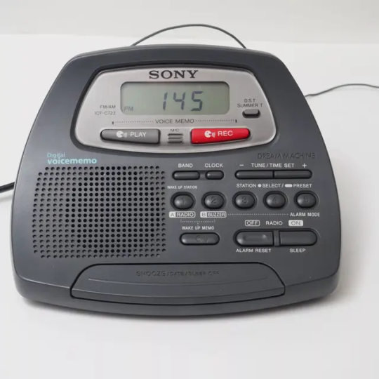

It's also a voice recorder: the Sony ICF-C723

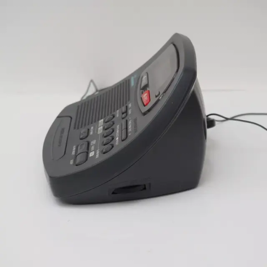
How does it work? The Sony ICF-C723 isn't a full-fledged voice recorder. But it can store one voice memo at a time, which you record using the big red button and play back using the play button on the left. Voice memos are recorded using a built-in mic and stored digitally.
You can also set your voice memo to play at the alarm time, by pressing the "Wake Up Memo" button. The recording plays before your alarm sound (which sounds a little startling, TBH) and then again when you stop or snooze the alarm.
Is it useful? YES!!! Seriously, I wish I had a clock with this feature. Do you know how many times I have a thought before bed, and then have to turn on all the lights and get my phone or a notepad and write it down? Imagine being able to roll over, whack a button on your alarm clock, say whatever you're thinking, and have it there for you in the morning. And with the "Wake Up Memo" feature, you can even have the clock nudge you about it, so you don't forget!
What other features does the clock have? It has a radio with digital tuning, a date display, and a 30-minute self-powered backup!
Do other alarm clocks have this feature? Not many! The only other one I know of from a major brand is the Aiwa FR-IC555.
(Update: I've since discovered that the Sony ICF-C88W and Philips AJ3138 also have this feature, and the Philips AJL305 I discussed recently has a voice recorder that works as a full-blown message center!)
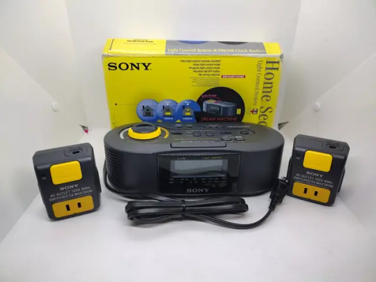
It's also a home security system: the Sony ICF-C900HS

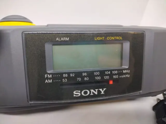
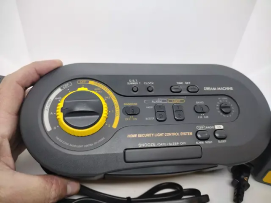
How does it work? Before I can explain what this alarm clock is, I need to explain what an outlet timer is. Imagine a fairly simple electric device, like a lamp. A lamp lights up whenever electricity is "flowing" through the lamp. (I'm pretty sure electricity doesn't really "flow," but that's not the point right now.) A lamp doesn't light up whenever the flow of electricity to the lamp is stopped.
When you plug a lamp into an outlet, the lamp will light up if electricity is flowing from the outlet, through the lamp, to the lightbulb. It won't light up if electricity is blocked before it comes out of the outlet (like if the outlet is controlled by a wall switch that's turned off), or if electricity is blocked before it enters the lamp's wiring (like if the lamp's own power switch is turned off).
An outlet timer is a device that fits between the outlet and the lamp (or other appliance). You plug an outlet timer into an outlet that is always powered. So no electricity is blocked there. Then you turn the lamp's power switch on. So no electricity is blocked there. The outlet timer is the deciding factor for whether the lamp turns on or not. You program the outlet timer so that, at certain times of day, the outlet timer allows electricity to flow, turning the lamp on. At other times, the outlet timer blocks the flow of electricity, turning the lamp off.
Here's a photo of a random outlet timer, so you get what I'm talking about:
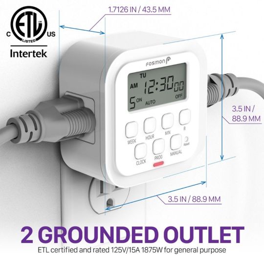
So what does that have to do with the funky alarm clock I showed you a second ago? The Sony ICF-C900HS comes with two outlet timers, which are the little gizmos to the left and right of the clock in the first photo. Only, these outlet timers don't have controls on them. You program these outlet timers on the alarm clock, and then the alarm clock sends a wireless signal to the outlet timers to turn your lamps on and off.
The reason Sony calls this clock a "home security system" is that it's designed to turn two of your lamps on and off at different intervals, so that if someone looks in your window, they will see your lights changing throughout the day and will think someone is home. It's supposed to deter intruders.
On the alarm clock, you program an "on time" and an "off time" for outlet 1 and outlet 2. Then you rotate the yellow dial on the top of the clock to activate the schedule for either outlet timer (or both). The clock wirelessly commands both outlet timers to turn your lamps on and off at the scheduled times! For added realism, you can also choose an "Auto" schedule that ignores your scheduled times and cuts the lights on and off multiple times a day, or you can turn on a "Random" feature that takes your selected schedule and adjusts it slightly on different days. (Because no one turns the lights on at 8 AM sharp every day.)
Is it useful? I think the idea of an outlet timer that turns your lights on and off is very useful! I don't know if it actually deters intruders, but I can imagine the peace of mind is helpful if you're on vacation and want people to think you're home.
I don't know if it's essential to have the controls for an outlet timer built into an alarm clock, since they kind of have nothing to do with the alarm clock itself! But if you want to change the settings, you don't have to run around the house clicking around on the little outlet timers. You just walk over to your nightstand! So that's handy.
What other features does the clock have? It has a radio with analog tuning, plus a date display!
Do other alarm clocks have this feature? As far as I know, absolutely none!
(Commentary before we continue: I was going to write less on each of these clocks so we could fit more into a post. Clearly I've already failed at that! Time to get back on the bandwagon so I don't have to make this a two-parter...)
It's also a CD changer: the Aiwa FR-TC5000 / FR-TC5500
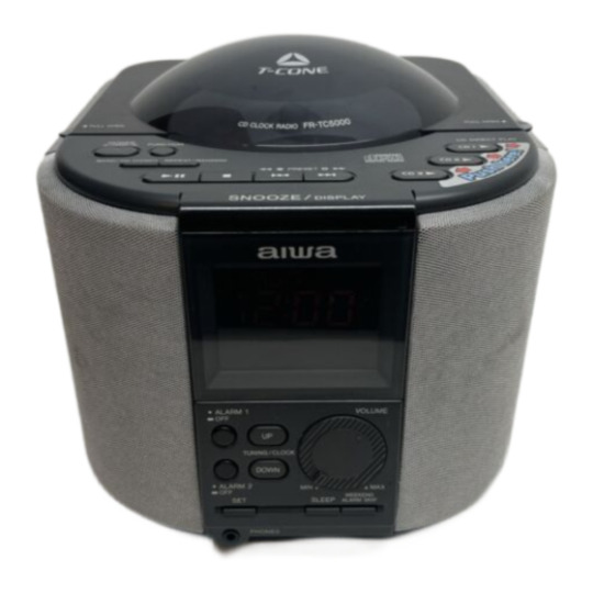
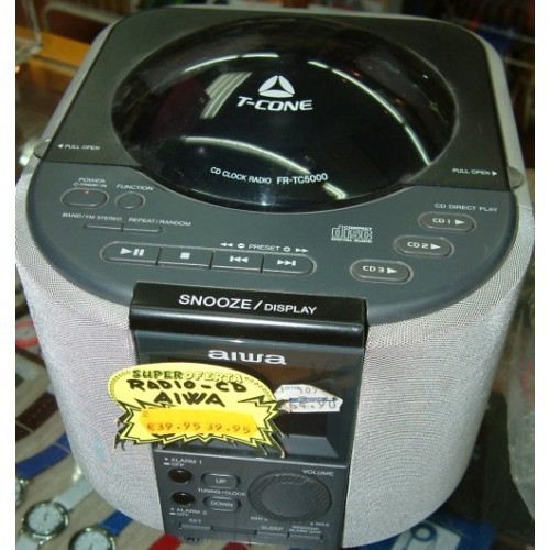

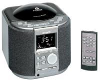
(Note: As far as I can tell, the FR-TC5000 and FR-TC5500 are identical, except that the latter includes a remote control.)
How does it work? There are lots of alarm clocks with CD players, but this model takes things to the next level by including a CD changer! (For the unfamiliar, a CD changer is a device that allows you to load more than one CD at once, and switch between them using controls on the device, rather than having to individually insert and remove CDs.)
Below is a diagram from the instruction manual of how the CD changer works. Like most CD alarm clocks, you lift a lid on the top of the clock, revealing a tray that you snap the CD onto. But the twist is that, if you press a button, the CD tray rotates out of view and is replaced by another tray. There are 3 trays in total, allowing for 3 CDs.

This mechanism, which Aiwa calls "T-Cone," is the only CD changer I've ever seen that works this way. I think (though I don't have proof) that the design would require 3 lasers and lenses, one for each CD, instead of using a single laser and lens for all CDs. If that's true, it would be very atypical!
Is it useful? Uh...kind of! I feel like CD changers are really helpful in cars, where you don't want to be futzing around with CDs every time you want to listen to different music. But for a machine on your bedside, I don't know that it's that hard to change the CD yourself. But if you're doing something else, like folding laundry or working at your desk, it could be pretty convenient to change CDs via the remote control!
What other features does the clock have? It's pretty much a full-featured stereo system. The CD player has repeat, random, and program modes, the AM/FM radio has digital tuning and preset stations, and there's even a headphone jack. As noted above, the FR-TC5500 also includes a remote control (though it can't control volume, because the volume control is analog). Both models also include a "Weekend Alarm Skip" feature that, when enabled, turns the alarms off automatically on weekends!
Do other alarm clocks have this feature? None that I know of!
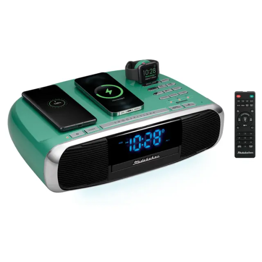
It's also a charging station: the Studebaker Workstation

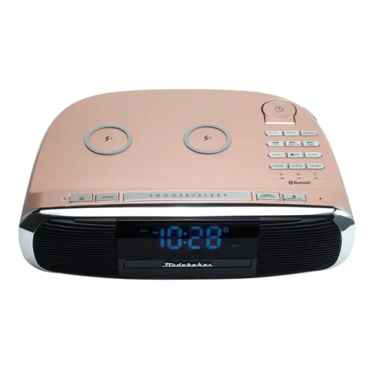
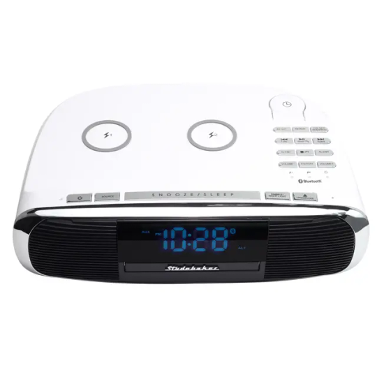
How does it work? Let's shake things up with an alarm clock you can still buy! (For a hefty $250 on Amazon, good gosh.) It's made by Studebaker, a company that makes retro-styled alarm clocks and record players and such things. (Studebaker used to be the name of a major manufacturer...of cars. I guess this new company that uses the name figures no one actually remembers what Studebaker was anyway.)
Many of us have nightstands cluttered with phones and earbuds and smartwatches that need charging, and this clock wants to help with that! It has two Qi wireless charging pads for smartphones. (You know, so you can charge both of your phones, like everyone does. We all have two phones. Obviously.) (To be fair, these can also charge things like AirPods.) Then there's a third charger specifically for an Apple Watch. And then there's a USB port on the back that you can plug a charging cable into. So you can charge four, yes, four devices on this clock at the same time.
Is it useful? I mean...kinda, yeah! If you've got the whole shebang of electronic gizmos (phone, AirPods, Apple Watch, unidentified fourth thing), this clock makes charging them way easier than if you had a big mess of cords. I'm personally wary of chargers for Apple devices that aren't officially licensed by Apple, but I'm not sure I have any reason to be.
What other features does the clock have? Um, all of them, apparently? An FM radio with digital tuning and presets, a CD player with repeat and program modes, Bluetooth connectivity so you can play music from your phone or answer phone calls, an aux-in jack, a remote control, equalizer presets, a digital volume control that allows for gradually-increasing (and configurable) alarm volume, and a nightlight.
And here's my favorite: it doesn't just receive Bluetooth, so you can play music from your phone. It also transmits Bluetooth, so you can listen to the CD player with Bluetooth headphones. Imagine. You have all the latest gadgets. You're charging your iPhone 16 Pro Max, and your brand-spanking-new AirPods 4, and your Apple Watch Ultra (because of course). And then you pull your AirPods off the charger...to listen to your CDs. Your CDs. Like it's 2005.
Do other alarm clocks have this feature? Lots of alarm clocks can charge your phone! Some can even charge two things at once. But as far as I know, four different chargers, including two different Qi pads, is a record.
(Update: It turns out that alarm clocks that can charge four devices at once aren't as rare as I thought! Though few are as weird as the Studebaker Workstation. The iHome iWW33 I discussed recently is another good example!)
It's also a diffuser: the HoMedics SoundSpa Slumber Scents


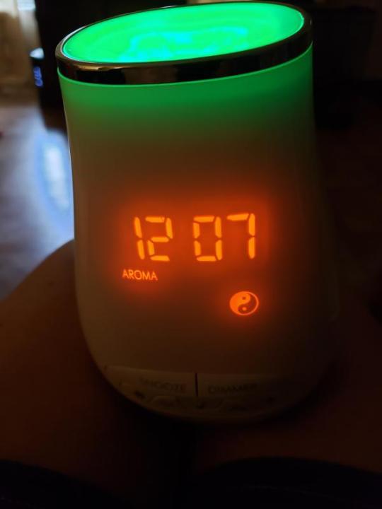
How does it work? There's actually not much to explain here! It's a diffuser! As in, a little gadget that gradually sprays essential oils into the air, like a fancy scented candle. (People love these.) I don't know how diffusers work, but this website has a nice explanation!
HoMedics is a weird alarm clock manufacturer, because they are more of a wellness company. They're best known for their massagers. (I actually have one of their foot massagers, and it's a lifesaver.) Then a long time ago, they branched out into nature sound machines (to help you relax or fall asleep), which they branded SoundSpa. Then they pulled a combo and released SoundSpas with alarm clocks built-in, to save space on your nightstand. And then they pulled another combo to make this device, the SoundSpa Slumber Scents, putting together a nature sound machine, an alarm clock, and a diffuser in one package! (Along with a color-changing light and a Bluetooth speaker for good measure.)
Is it useful? Heck yeah! This alarm clock is unfortunately discontinued, but it's pretty recent, with the manual's copyright date implying it released around 2017. According to the HoMedics website, it sold for $90, and I think it would have been a phenomenal gift for someone interested in wellness! (I can think of some folks myself who would have loved this.) I mean, it gives off pretty scents, it plays soothing sounds so you can fall asleep, it sets the mood with the nightlight, it's compact and pretty cheap... What's not to love?
What other features does it have? Besides an alarm clock, nature sound machine, diffuser, color-changing night light, and Bluetooth speaker, you mean? Hard to please... Well, it also has a USB port to charge your phone, and you can set the alarm to play a nature sound (or beeping sound), turn on the diffuser scent, and turn on the color-changing light. Nifty!
Do other alarm clocks have this feature? Though I've seen many clocks with nature sounds and even some with a color-changing night light, I've never seen another clock with a diffuser!
(Update: I found another alarm clock with a diffuser! It's the iHome Zenergy Aroma Dream, model iZA40. It doesn't have the Bluetooth speaker or color-changing light features of the HoMedics clock, but it adds twice the soothing sounds, dual alarms that can be set to sound only on weekends or weekdays, and a remote control! I'll post some info about it in the Google Drive folder linked from my welcome post.)
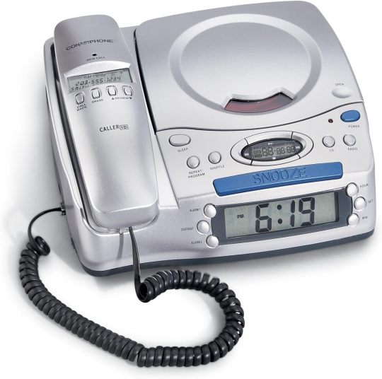
It's also a telephone: literally more alarm clocks than I can count

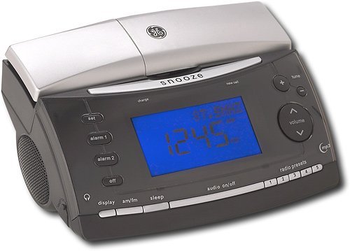
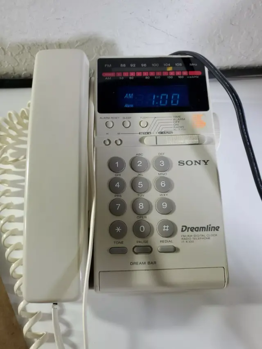
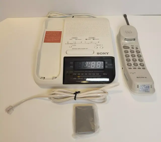
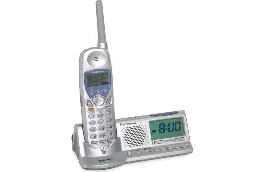
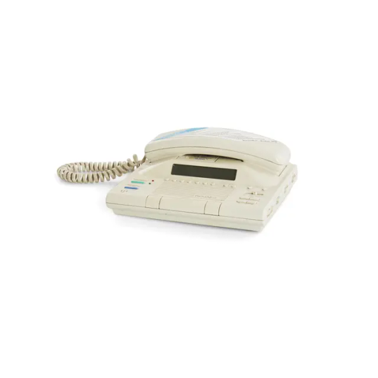
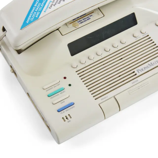
Legend:
First row: Conairphone CID502
Second row: GE 27980GE3, Sony IT-K300
Third row: Sony SCT-100, Panasonic KX-TGA273S
Fourth row: PhoneMate (model number unknown) (both photos)
How does it work? Remember landlines? Back before cell phones, your house was wired with phone jacks in different rooms. You connected a phone to each phone jack, then used it to make your calls. If you were lucky, you had a cordless phone, where the base station stayed plugged into the phone jack, but the handset was portable and communicated with the base wirelessly.
To avoid running across the house when the phone rang (or carrying a cordless phone from room to room), many folks liked having landline phones in different rooms, including the bedroom. But that's another thing taking up space on your nightstand, and we can't have that! So alarm clock makers made tons and tons and tons of alarm clocks that were also landline phones!
Some of these alarm clock/phone combos also had radios. Some even had CD players. Some had cordless phone handsets. Some were actually designed to work as part of a cordless phone system, where you didn't need a phone jack in each room because the phone communicated with a base station elsewhere in the house. One of them, the PhoneMate pictured above, had a cassette-based answering machine (because that was also a thing back in the age of landlines!).
Is it useful? Definitely! I mean, if you're going to have a landline phone and an alarm clock on your nightstand, what does it hurt to combine them?
That's it!
Geez...I always underestimate the length of these posts before writing them. This one's a chonker, that's for sure! I hope it brought you some joy, and I hope you took breaks or skimmed as needed to make it manageable. See you soon for more alarm clock mayhem!
Image credits:
Sony ICF-C723: eBay
Sony ICF-C900HS: eBay
Outlet timer: Fosmon
Aiwa FR-TC5000 / FR-TC5500 (first photo): ManualsLib
Aiwa FR-TC5000 / FR-TC5500 (second photo): Bazar Canarias Talavera
Aiwa FR-TC5000 / FR-TC5500 (third photo): eBay
Aiwa FR-TC5000 / FR-TC5500 (fourth photo): UsedPrice.com
Aiwa FR-TC5000 manual: ManualsLib
Studebaker Workstation: Studebaker
HoMedics SoundSpa Slumber Scents: HoMedics
Conairphone CID502: Amazon Canada
GE 27980GE3: Best Buy
Sony IT-K300: eBay
Sony SCT-100: eBay
Panasonic KX-TGA273S: Crutchfield
PhoneMate (model number unknown): Gil & Roy Props
0 notes
Text
youtube
100 LED Chaser Circuit Using IC555 and CD4017
A Chaser Circuit consists of a clocked IC or other electronic unit like an Arduino that drives an array of LEDs in such a way that individual LEDs (or small groups of LEDs) turn on and off in a predetermined and repeating sequence producing a visually attractive pattern.
In this tutorial I am going to create a chaser circuit that can drive 20 or more LEDs using 555 timer IC and CD4017 decade counter. Watch this video for detailed step by step instructions on how to build this circuit and for a complete instruction on how the circuit works.
1 note
·
View note
Video
شرح دائره ال 555 وفكره عملها وطريقه تركيبه وشرح مكوناتها واهم استخداماتها
1 note
·
View note
Photo
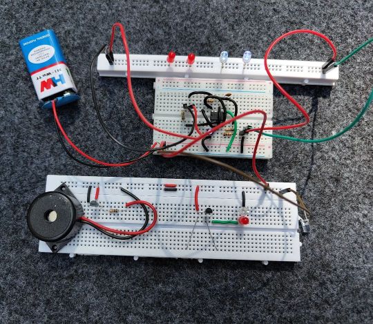
Some simple timer circuits #time #electronics #circuit #ic555 #electronicsprojects #tech #electronicslover #maker https://www.instagram.com/p/CmUDV-gvsR8/?igshid=NGJjMDIxMWI=
1 note
·
View note
Link
One of the most important discoveries of the times for obese people is a bariatric bed. We will learn a lot more about this product in a detailed explanation.
https://icarebedsau.tumblr.com/what-is-a-bariatric-bed-used-for/
0 notes
Link
The IC555 model is our premium bed in the Original range. This is a IC555 Bariatric Bed model with extra features, including vascular support and the option of vinyl or fabric.
https://www.icaremedicalgroup.co.nz/product/ic555/
#IC555#IC555 Model#IC555 bed#IC555 Bariatric Bed#IC555 Bariatric Bed model#Bariatric Bed model#Bariatric Hospital Bed
0 notes
Photo
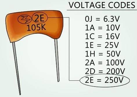
Check the voltage rating. Follow for more 👇👇👇👇👇👇👇👇👇 @electronics_curiosities Electronics Curiosities 💓 Follow for more 👇👇👇👇👇👇👇👇👇 @electronics_curiosities Follow for more 👇👇👇👇👇👇👇👇👇 @electronics_curiosities Like Share Comment 👍 #electronicscuriosities #electronics #electronicspoint #electronicdevices #electronicengineering #electronicengineer #electronicproject #prototype #arduinoproject #engineeringprojects #analogelectronics #digitalelectronics #powerelectronics #ic555 #chip #electronica #electroniclovers #electronicdevice #timerpics #circuit #circuitboard #mechatronics #arduinolove #electrical #diyprojects #electronicprojects #sparkfun https://www.instagram.com/p/CKq-5j2A4RL/?igshid=1hga8usq3zquc
#electronicscuriosities#electronics#electronicspoint#electronicdevices#electronicengineering#electronicengineer#electronicproject#prototype#arduinoproject#engineeringprojects#analogelectronics#digitalelectronics#powerelectronics#ic555#chip#electronica#electroniclovers#electronicdevice#timerpics#circuit#circuitboard#mechatronics#arduinolove#electrical#diyprojects#electronicprojects#sparkfun
0 notes
Photo
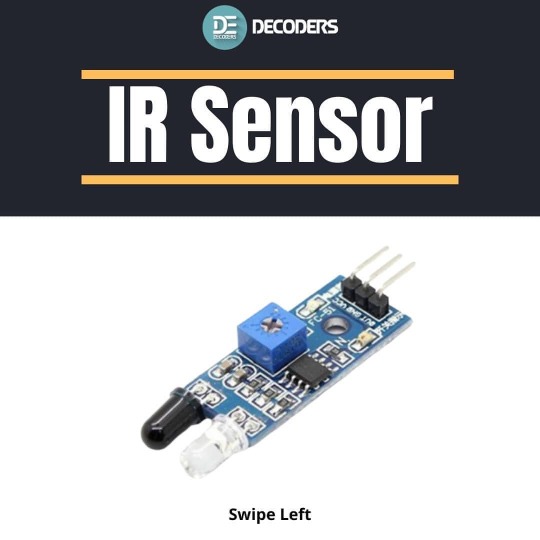
IR sensor - - - - - - - - - ➖➖➖➖➖➖➖➖➖➖➖➖ Follow Us On: @decoders8421 Tag Your Friends 👼. Ask any query or doubt in comments. ➖➖➖➖➖➖➖➖➖➖➖➖ - #electronics #sensor #irsensor #breadboard #extc #circuit #resistor #capacitor #arduino #sensormodule #pirsensor #arduinouno #raspberrypi4 #raspberrypi3 #raspberrypizero #esp32 #nodemcu #ic555 #vlsi #pcbdesign #pcb #electronicsengineering #smd #project #arduinofun https://www.instagram.com/p/CA0FzipnafS/?igshid=f9hslxeg1cq6
#electronics#sensor#irsensor#breadboard#extc#circuit#resistor#capacitor#arduino#sensormodule#pirsensor#arduinouno#raspberrypi4#raspberrypi3#raspberrypizero#esp32#nodemcu#ic555#vlsi#pcbdesign#pcb#electronicsengineering#smd#project#arduinofun
0 notes
Link
I am going to discuss a very simple IC555 based timer alarm circuit that can have a time duration range from as low as 5 minutes and as high as 30 minutes. In this timer based alarm circuit, you can select the alarm time delay duration.
1 note
·
View note
Photo

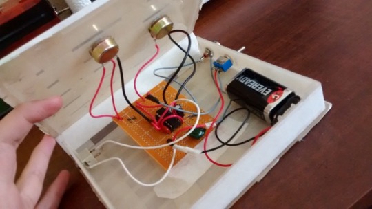
vimeo
probando la atari punk en una caja de nintendo
0 notes
Photo
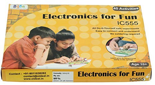
Kutuhal Electronics for Fun - IC555 Based Do-It-Yourself Educational Electronics Science Activity Kit https://news99india.in/?p=8157&feed_id=8436&_unique_id=5f5fb224ef174
0 notes
Link
The IC555 model is our premium bed in the Original range. This is a IC555 Bariatric Bed model with heavyweight rating. Upholstery option of vinyl or fabric. https://icaremedicalgroup.com.au/product/ic555/
0 notes
Photo
The IC555 model is our premium bed in the Original range. This is a IC555 Bariatric Bed model with extra features, including vascular support and the option of vinyl or fabric.
https://www.icaremedicalgroup.co.nz/product/ic555/
#IC555#IC555 Model#IC555 bed#IC555 Bariatric Bed#IC555 Bariatric Bed model#Bariatric Bed model#Bariatric Hospital Bed
0 notes
Photo
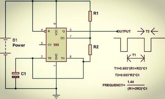
IC 555 Timer Ton ,Toff and frequency formula for designing desire timer output. The 555 timer IC is an integrated circuit used in a variety of timer, delay, pulse generation, and oscillator applications. Derivatives provide two or four timing circuits in one package. Introduced in 1972 by Signetics, the 555 is still in widespread use due to its low price, ease of use, and stability. Follow for more 👇👇👇👇👇👇👇👇👇 @electronics_curiosities Electronics Curiosities 💓 Follow for more 👇👇👇👇👇👇👇👇👇 @electronics_curiosities Follow for more 👇👇👇👇👇👇👇👇👇 @electronics_curiosities Like Share Comment 👍 #electronicscuriosities #electronics #electronicspoint #electronicdevices #electronicengineering #electronicengineer #electronicproject #prototype #arduinoproject #engineeringprojects #analogelectronics #digitalelectronics #powerelectronics #ic555 #chip #electronica #electroniclovers #electronicdevice #timerpics #circuit #circuitboard #mechatronics #arduinolove #electrical #diyprojects #electronicprojects #sparkfun https://www.instagram.com/p/CJIKVGfg-KI/?igshid=16d9em52a69xn
#electronicscuriosities#electronics#electronicspoint#electronicdevices#electronicengineering#electronicengineer#electronicproject#prototype#arduinoproject#engineeringprojects#analogelectronics#digitalelectronics#powerelectronics#ic555#chip#electronica#electroniclovers#electronicdevice#timerpics#circuit#circuitboard#mechatronics#arduinolove#electrical#diyprojects#electronicprojects#sparkfun
0 notes
Photo
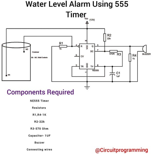
🔌#Follow👉 Featured By.. @tech__tag .... ... @circuitprogramming & #circuitprogramming • • 🔶 💓Like || comments📝 || Share📤 🔶 Keep Supporting 😊👍 🔶 Repost Allowed ✔✔ 🔶 Please turn on page up notification ◽ ◽ . . 🔌#technologies #technology #tech #technews #technologynews #innovation #techgeek #techworld #engineering #techy #technologie #techies #technologythesedays #resistor #newtechnology #indicator #techlover #futuretech #technologyrocks #waterlevel #instatech #ic555 #informationtechnology #instatechnology #design #transistors #newtech #futuretechnology @circuitprogramming @circuitprogramming (at New York City , USA) https://www.instagram.com/p/B_-G78tgBbC/?igshid=105blm6hy7x37
#follow👉#circuitprogramming#technologies#technology#tech#technews#technologynews#innovation#techgeek#techworld#engineering#techy#technologie#techies#technologythesedays#resistor#newtechnology#indicator#techlover#futuretech#technologyrocks#waterlevel#instatech#ic555#informationtechnology#instatechnology#design#transistors#newtech#futuretechnology
0 notes
Text
How to Design PCB or Other Circuit Boards: The Basics
In the world of electronics, PCBs or circuit boards are the most integral part of any electronic device. They are often disregarded since they are hidden underneath the electronic device’s shell but they are indeed the backbone to any appliance, electronic gadgets and devices you own. The PCB (printed circuit board) houses all the electronic components of a device and electronically connects each other to create a circuit. It is rightfully designed to keep all the electrical wires fixed and other components in place. If you are into electronics manufacturing, it would be no surprise if you are wondering how to design a PCB board and you are most likely eager to know PCB design steps. Even though you can always purchase ready-made circuit boards, it would be too expensive most especially if you are only a small electronics business. Doing it yourself is definitely the way to go as a small-time electronics manufacturer. There are 3 different ways on how to design a circuit board; Circuit by hand Iron on glossy paper Laser cutting method The laser cutting method is the top technology used in the industry when it comes to creating printed circuit board designs. It requires laser machinery which is too expensive for small and even up to mid-sized businesses. In this wiki article, let us focus on the other two methods on how to design a PCB board: circuit by hand and iron on glossy paper. If you want to get a full understanding of how PCB design works in detail, we recommend the online courses from Udemy and Fedevel.

Step by Step Process on How to Design PCB (Circuit Board)
First things first, you need to draft your circuit’s schematic diagram before thinking of putting it on to the circuit board. Fortunately, there are already a lot of free software out there who can take care of the PCB layout design. Some of them are paid packages who can give in-depth outlook to the PCB layout design and it would be up to you whether you’d pick the free or paid ones. Once the PCB layout design is ready, you now have to secure the materials needed as part of PCB design guidelines. Here are the materials you need; Copper plate Etching solution Glossy paper Black marker Cutter Sandpaper Kitchen paper Cotton wool Steel wool For this sample on how to design a circuit board, let us consider making a PCB design for a simple touch switch device using IC555. 1. Have a printout of your circuit board layout. Have your circuit board layout printed using the glossy paper and make sure the print is on the glossy side of the paper. Choose the output in black on both from the PCB design layout and the printer’s settings. 2. Cut a copper plate for the PCB. Cut the copper plate according to the proper size of your PCB layout. The smaller the plate will be better for the overall outcome since we want to keep things small and minimized but at the same time spacious to keep all the electrical components. Rub the copper side of the PCB with a steel wool to remove the oxide layer of copper along with the photoresist surface. Having a smooth surface allow the image from the printout to stick better. 3. Transfer the printout on to the copper plate. Transfer the printout by putting it on the copper surface of the PCB and ensure the board is properly aligned on the borders. If necessary, tape the printout on the board to hold it in the right position. For the next step, here is where it becomes a two-way street since the two different methods on how to design a PCB board mentioned above will come into play. a. Circuit by Hand While referring to the circuit, trace the circuit board layout on the copper plate using a pencil. Once you are satisfied of your sketch, retrace it again with a permanent black marker. b. Iron on Glossy Paper This is the other method wherein you iron the printed glossy paper side down on to the copper side of the plate. Simply put the glossy paper on top of the copper plate with the back of the glossy paper on the surface. Use a pair of pliers to keep the glossy paper and copper plate in place then put the flat iron on the opposite end for 8-10 seconds. Repeat the process for other surfaces and just move around your grip on the pliers to keep it in position. Once you have covered the entire gloss paper surface, iron the gloss paper all along the edges with a little applied pressure for 10 to 15 minutes. This ironing process transfers the ink on to the copper plate due to the heat. Be wary of the copper plate’s hot surface due to the hot iron. After ironing, put the copper plate in lukewarm water for 10 minutes. The paper will right away dissolve making it easy for you to peel it off. However, there are times when the ink gets fainted after peeling but you can easily solve it by tracing it all over again with a black marker. 4. Etch the plate. This is arguably the most crucial step on how to make PCB: the etching process. You have to be very careful during this process by first putting on sanitary gloves for protection. Put some paper on the bottom end so the etching solution will not leave marks on the floor. Meanwhile, fill a plastic box with water then dissolve 2-3 teaspoons of your etching solution popularly ferric chloride in the water. Submerge the PCB into the solution and leave it there for half an hour. The etching solution reacts with the copper surfaces removing the copper with no marks on it from the PCB. In case it is not properly etched, leave the board again in the solution for a few more minutes. Take out the useless copper with a pair of pliers. 5. Cleaning and final touches for the PCB. The etching solution is very toxic and you have to dispose it properly. Do not simply drain it down your sink since it may damage your pipelines. Instead, dilute the solution with more water and throw it somewhere outside your house. To remove the remaining ink on the PCB, a few drops of thinner on a slab of cotton will get the job done. Simply rub it on the surface then rinse carefully with water and wipe dry with a cloth or kitchen paper. Trim the board to your desired size then smoothen the edges through sandpaper. For the final step, drill holes on the printed circuit board design using a PCB driller. Use a soldering iron to attach all your cool components to the board. If you want the traditional green-colored printed circuit board design, apply solder resistant paint on top of some PCB lacquer. Carefully follow these PCB design guidelines and now you have your DIY cost-efficient PCB or circuit board. The casing for the PCB is usually done by starting out with 3D design and continuing with plastics manufacturing. Read the full article
0 notes