#how to test mosfet
Explore tagged Tumblr posts
Visit Tumblr Blog
Explore Tumblr blogs with no restrictions, modern design and the best experience.
Last Seen Tumblr Blogs


Fun Fact
The “We are the 99%” Tumblr blog became the slogan for the Occupy Wall Street movement.
Text
Mosfet Testing......
#working #mobile #repair #mobilephone #mobilerepair #mobiles #mosfet #mobilephonerepairspecialist #MOSFET #mobicationhub #mobicationhub9509959090 #testing #mobilerepairtools #iPhone #androidrepair
#mosfet testing#mosfet#how to test mosfet#mosfet transistor#mosfet testing with multimeter#how to check mosfet#how to check mosfet with multimeter#easy method of testing mosfet#how to test mosfet using multimeter#n channel mosfet#smd mosfet testing#how to test mosfet with multimeter#how to test a mosfet#test mosfet#n channel mosfet testing#mosfets#mosfet test#mosfet explained#easy way to test mosfet#p channel mosfet testing#mosfet tutorial
0 notes
Text
VNI4140K Specifications & Features Explained
The VNI4140K is a cutting-edge high-side smart power switch designed for industrial and automotive applications. But what makes it special? Why should engineers and tech enthusiasts care about it? This article dives deep into its specifications, features, and applications, making it easy to understand—even for those unfamiliar with complex electronic components.
What is the VNI4140K?
The VNI4140K is an intelligent quad high-side power switch designed to handle loads with enhanced safety and efficiency. It integrates various protection features, making it ideal for automotive, industrial, and smart control applications.
Key Features of the VNI4140K
Quad-channel high-side switch
Over-temperature protection
Short-circuit protection
Overvoltage clamp
Low power consumption
Diagnostic feedback for fault detection
Technical Specifications
Operating Voltage: 8V – 36V
Maximum Load Current: 2A per channel
On-Resistance (Rds ON): 0.1Ω (typical)
ESD Protection: Yes (IEC 61000-4-2 compliant)
Temperature Range: -40°C to 150°C
Package: PowerSSO-36
Pin Configuration and Functions
The VNI4140K comes in a PowerSSO-36 package with dedicated input, output, and diagnostic pins. Key pins include:
VCC: Power supply input
IN1-IN4: Control inputs
OUT1-OUT4: Output channels
GND: Ground
FAULT: Diagnostic feedback
How the VNI4140K Works
The VNI4140K acts as a smart electronic switch, replacing traditional mechanical relays. It uses MOSFET technology to efficiently control high-current loads while offering built-in safety features. The fault diagnostics system detects and prevents issues like overheating or short circuits.
Advantages Over Traditional Switches
Improved Energy Efficiency: Consumes less power compared to mechanical relays.
Enhanced Durability: Solid-state design minimizes wear and tear.
Faster Response Time: Reacts quicker to input signals.
Integrated Protection Features: Prevents circuit damage due to overcurrent or overheating.
Common Applications
The VNI4140K is widely used in:
Automotive electronics (lighting systems, door locks)
Industrial automation (motor controls, PLCs)
Smart home devices (intelligent power management)
Medical equipment (precision switching for diagnostics and monitoring devices)
Installation and Usage Guidelines
Ensure proper heat dissipation to prevent overheating.
Connect the diagnostic pin to a microcontroller for real-time monitoring.
Use appropriate filtering capacitors to stabilize the power supply.
Avoid exceeding maximum load limits to prevent system failure.
Troubleshooting and Maintenance Tips
Overheating? Ensure proper ventilation and heat sinks.
No output signal? Check control input voltage.
Short circuit detected? Inspect load connections and wiring.
Intermittent operation? Test for voltage fluctuations.
Conclusion
The VNI4140K is a powerful and reliable quad high-side smart switch designed for various industrial and automotive applications. With advanced protection features, low power consumption, and efficient performance, it offers significant advantages over traditional switching solutions. Whether you're an engineer or a tech enthusiast, understanding its specifications and features can help you integrate it effectively into your designs.
0 notes
Text
Understanding MOS Relays: The Future of Switching Technology - MANGOFY

In the world of electronics, the need for efficient, reliable, and fast switching is ever-growing. Traditional mechanical relays, while useful in many applications, have limitations like slower response times, mechanical wear, and the need for regular maintenance. This is where MOS relays, a solid-state alternative, come into play.
What is a MOS Relay?
A MOS relay (also known as a MOSFET relay) is a type of solid-state relay that uses a MOSFET (Metal-Oxide-Semiconductor Field-Effect Transistor) to perform switching functions. Unlike mechanical relays, MOS relays do not have moving parts, making them more durable, faster, and more efficient in many applications.
Key features of MOS relays include:
No Mechanical Wear: Since there are no moving parts, MOS relays do not suffer from the wear and tear associated with mechanical relays.
Fast Switching Times: MOS relays can switch on and off rapidly, which is essential in applications requiring high-speed operations.
Low Power Consumption: Because MOS relays use semiconductor technology, they consume significantly less power compared to traditional relays.
Noise-Free Operation: MOS relays operate silently, which is a key advantage in noise-sensitive applications.
How Do MOS Relays Work?
MOS relays utilize a photovoltaic coupler to control a MOSFET. When a small control signal (usually a low-voltage signal like from a microcontroller) is applied to the input, it activates the LED within the relay. The light from the LED generates a voltage in the photovoltaic element, which in turn controls the MOSFET, allowing or blocking current flow in the output circuit.
This method of switching provides:
Electrical Isolation: The control signal is isolated from the switched circuit, which enhances safety and reduces the risk of interference.
Precision Control: MOS relays offer fine control over switching, ideal for sensitive applications.
Applications of MOS Relays
MOS relays have a wide range of applications, particularly in situations where high precision, reliability, and fast switching are required. Here are a few areas where MOS relays are commonly used:
Test Equipment: In precision measurement and testing equipment, MOS relays are used for switching signals without introducing noise or signal degradation. Their high speed and long lifespan make them ideal for automated test systems.
Telecommunications: In telecommunications infrastructure, MOS relays are employed for switching high-speed data signals. Their ability to switch quickly and without noise is crucial for maintaining signal integrity in high-frequency applications.
Automotive Electronics: MOS relays are increasingly used in automotive applications where reliability and durability are paramount. With the rise of electric and hybrid vehicles, MOS relays are used in systems like battery management, electric motor control, and various safety systems.
Industrial Automation: In factories and automated environments, MOS relays are employed for controlling motors, actuators, and sensors. Their durability and speed make them ideal for applications where fast switching is necessary to keep up with automated processes.
Renewable Energy Systems: Solar power systems, for example, often use MOS relays in their inverter circuits and battery management systems. The low power consumption and fast switching times help improve the efficiency and longevity of these systems.
MOS Relays vs. Mechanical Relays
Advantages of MOS Relays:
Durability: Without moving parts, MOS relays have a much longer operational life.
Speed: Mechanical relays are slower due to the physical movement required to make or break a connection. MOS relays, being solid-state, can switch in microseconds.
Power Efficiency: MOS relays consume less power, making them ideal for energy-conscious applications like battery-powered devices.
Noise-Free Operation: Since MOS relays do not physically move, they operate silently, which is critical in applications like medical devices and audio equipment.
Disadvantages of MOS Relays:
Cost: MOS relays tend to be more expensive than mechanical relays due to their advanced technology.
Current Rating: Mechanical relays can handle higher currents compared to MOS relays, which may have limitations in high-power applications.
Why MOS Relays are Crucial in Modern Electronics
As electronics continue to evolve toward more compact, efficient, and reliable systems, MOS relays are becoming an essential component. Their solid-state nature makes them more suitable for modern applications, where mechanical parts may be prone to failure and inefficiencies. Whether it's in consumer electronics, industrial automation, or renewable energy, MOS relays offer a compelling alternative to traditional relays, providing faster, quieter, and longer-lasting performance.
Conclusion:
With the increasing demand for more reliable and efficient switching technology, MOS relays are proving to be the future of electronics. Their fast switching times, low power consumption, and long operational life make them ideal for a wide range of applications—from high-speed data communication systems to advanced industrial automation. As industries continue to innovate and push the boundaries of technology, MOS relays will play a crucial role in ensuring high-performance, precision, and efficiency.
1 note
·
View note
Text
Everything Old is New again.
Mr Audiophiliac put up his Dynaco ST 70 amp review. As I expected he loves it and even bought it.
The ST 70 is a 1959 era stereo tube amp that puts out 35 Watts per side. It is probably the most common tube amp out in the wild and they number in the many many thousands. It was very good in 1959, when all amps available were tube. It was available as a kit and many were assembled when knowing how to use a soldering iron was quite common. Having assembled and rebuilt Dynaco tube and transistor amplifiers I know the process. Dynaco tube amps are MUCH easier to build.
So yes he loved it. He tested it with some strange speakers including the Chinese knock off LS3 5/A.
To a certain degree if you put a signal into any device like an amp or a speaker you get a facsimile of the real version. How close is the tricky bit. But some things like those knock off speakers will alter the response of the system sometimes dangerously. They are cheap knock offs remember.
Aside from everything else 35 Watts is not enough in my opinion for a good system. My CL60 is almost too small for some music I listen to at 60 Watts per side. (more below)
And as that guy is older and has a thing for tube amps he is predisposed to like some stuff that is questionable. Actually the really interesting thing about his presentation was a link to where he got the amp.
youtube
This guy did the restoration work and tested it and a modified version. Look a young guy! His tests are interesting. Note the ASR testing guys did a ST 70 and it did very poorly.
I liked that he did listening tests as well. It would have only been better if they had a control amplifier like a nice MOSFET unit to compare both to. The listening results are particularly good in that the two machines test very different. On the bench one is clearly better, but on the couch with music the experience is totally different.
Distortion is good!?
I need to point out that the test numbers Novalux got were using a lab load. That is usually a straight resistor that can handle many Watts of power. A simple resistor is really easy for an amp to handle. A speaker with a cross over filter is completely different. That can massively change frequency response and distortion.
Regarding power:
I listened to some tunes last night. I have the Mangione "Children of Snachez" sound track LP. It has some amazing Bass. If you play it loud you feel it. Not just in the drums, and bass guitar, but also the horns have impact. You need Watts to get that. You need available current to push the speakers around.
I also listened to Cat Stevens "Catch Bull at 4". I really like that album. It has great range and was well recorded and mastered. There are many layers to the songs both sonically and literally. My favorite is O Caritas which is song in Latin. It is a ballsy song. Again you have to have power behind it.
I have played on both sides of the solid state / vacuum schism. I continue to do so. They are both fun.
The point is to have fun and enjoy music.
0 notes
Text
ASUS Platinum PSUs: High-Performance Power Supply Series

ASUS Platinum PSU
ASUS Republic of Gamers (ROG) unveiled the ROG Strix Platinum PSU line, suited for gaming PCs. These high-efficiency 1200-watt, 1000-watt, and 850-watt devices offer lower connection temperatures, intelligent wattage delivery, ATX 3.1 with Intel lab testing, and a generous 10-year guarantee.
Platinum PSU
The ROG Strix Platinum PSU series can power any rig, regardless of graphics card. The proprietary GPU-First intelligent voltage stabilizer (IVS) helps. The stabilizer provides up to 45% more consistent power flow to the GPU than without it, allowing even overclocked graphics cards to run at peak capacity during strenuous gaming sessions. Users can unplug the Strix Platinum IVS connection for a CPU-focused voltage sensor.
- Advertisement -Image credit to ASUS
1000W PUS Platinum
A Diagram of a Computer Description Automatically Generated
A gallium nitride (GaN) MOSFET in ROG Strix Platinum PSUs reduces energy waste and improves optimum power delivery by 30% over prior generations. The GaN MOSFET’s compact size allows for a streamlined internal structure with greater area for heat dissipation, heavy-duty heatsinks, and airflow.
Dual ball bearings on the PSU fan last up to 80,000 hours, ensuring this power supply will last no matter how much gaming is done. The fan will intelligently deactivate after reaching safe temperatures when the PSU load is 40% or lower with 0dB mode selected, keeping a rig quiet. In non-0dB mode, the ROG Strix 1000W Platinum PUS emits less than 20 dB of noise, earning it an A+ Cybenetics Lambda certification for excellent quietness.
This PSU series is Intel lab-tested and 80 PLUS Platinum certified. Due to high-end Japanese capacitors that last twice as long as regular capacitors, consumers always enjoy at least 89% efficiency, whether the load is low or heavy. High energy efficiency and limited temperature range result in calm acoustics and lower energy bills with a Platinum rating. High-performance copper pins on updated PCIe connections reduce connector temperatures and boost thermal conductivity.
Custom power supplies for DIYers
ROG Strix Platinum PSU power solutions are next-generation due to modularity. Besides amazing features, these PSUs offer easy installation and organization with flexible, etched modular wires that work at up to 50°C below the safety limit. They also meet UL1581 flame test standards and are UL758 certified, so DIY gaming PC builders can trust the Strix Platinum to meet their needs safely and sustainably.
- Advertisement -
ASUS added a unique CPU power cord to the ROG Strix Platinum PSU for DIY PC builders. Its distinctive color scheme and clip make it simple to spot. Users will immediately know which cable goes to the CPU.
Each Platinum series PSU comes with ROG Strix stickers, allowing users to customize their PSU to suit their aesthetic tastes. These sleek, angular PSUs already have ROG branding to show users they’re gaming with the best, but a little color may show a unique style.
ROG Strix Platinum PSUs redefine gaming power supply
Users demand a reliable power supply for their new powerful CPU or GPU. They need a premium PSU to secure their gear investments. For next-gen gaming builds, the ROG Strix CPU or GPUseries offers quiet operation, efficient operation, and powerful power supply.
Read more on govindhtech.com
#ASUSPlatinumpsu#HighPerformance#ATX31#cpu#PowerSupplySeries#graphicscard#StrixPlatinum#PSUseries#DIYPCbuilders#gpu#ROGStrixPlatinum#gamingpowersupply#1000WPUSPlatinum#technology#technews#news#govindhtech
0 notes
Text
How To Check Mosfet ....
#mosfet #institute #jaipur #topinstitutes #mobicationhub #repairing #repairtools #PracticalClass #mobilerepair #mobilerepairing #mobilephonerepair #mobicationhub9509959090 #topinstitutesofmobilerepair #howtocheckmosfet
#how to check mosfet#how to check mosfet with multimeter#mosfet#how to test mosfet#mosfet testing#mosfet transistor#how to check mosfet with digital multimeter#n channel mosfet#how to test mosfet using multimeter#how to test mosfet with multimeter#check mosfet#mosfet checking#n-channel mosfet#how to check if a mosfet is bad#how to test a mosfet#test mosfet#mosfet multimeter check#mosfet testing with multimeter#mosfets#easy way to test mosfet
0 notes
Text
Troubleshooting Common Issues In SMPS Designs

Despite their benefits, switched-mode power supplies (SMPS), which efficiently convert electrical power switching between different energy levels, can have a number of design flaws. During design, development, and operation, SMPS may run into a number of issues like component failure, excessive noise, overheating, and instability. To ensure dependable and effective functioning, it is crucial to comprehend these issues and know how to resolve them. This blog includes a thorough analysis of typical difficulties with SMPS designs as well as practical solutions for their diagnosis and troubleshooting.
Common issues in SMPS designs
Common issues in SMPS designs can significantly affect performance and reliability.
Instability and oscillation: A fluctuating or oscillating output voltage and insufficient control are common indicators of instability and oscillation. These problems are usually caused by inadequate phase margin, an inadequate compensation network, or a poorly designed feedback loop. In order to debug, the feedback loop needs to be appropriately built with a phase margin, and the stability of the loop properly analyzed using simulation tools. The components of the compensation network need to be checked, and the values of the resistors and capacitors need to be altered as necessary. To find instability situations and make necessary design adjustments, the loads need to be tested.
Excessive noise and EMI: High levels of electromagnetic interference or audible noise from the SMPS might be signs of excessive noise and EMI. Poor PCB layout, insufficient filtering, or rapid switching transients are frequently the cause of this. The PCB layout needs to be optimized to reduce loop regions and stable ground planes need to be provided in order to solve these issues. By employing the right capacitors and inductors and by improving or adding input and output filters, filtering can be improved. To manage switching transients and lower noise, soft switching strategies and snubber circuits must be used.
Overheating: Thermal shutdowns and overheated components, including switching transistors and diodes, are frequent signs of overheating. This may be the consequence of inadequate thermal management, high power dissipation, or inadequate cooling. Cooling must be improved by installing fans, heatsinks, or better airflow to address overheating, and enough ventilation must be available. To minimize power dissipation, components with reduced on-resistance should be chosen. For optimal heat transmission from heated components to heatsinks or the chassis, thermal pads and conductive materials must be used.
Component failure: The SMPS may malfunction or behave erratically as a result of a component failure; frequently, observable damage to parts like capacitors, transistors, or inductors is present. Overvoltage or overcurrent situations, subpar or underestimated components, and high operating stress are common causes. Multimeters and oscilloscopes must be used to find electrical problems and components should be physically checked for damage as part of the troubleshooting process. To avoid stress and failure, outdated components with higher voltage and current ratings should be replaced, and heat, overcurrent, and overvoltage safety circuits should be installed.
Poor efficiency: High power loss and excessive heat generation might result from inefficient operation. Suboptimal design, excessive conduction losses, or ineffective switching are frequently the causes of this problem. Using high-efficiency MOSFETs and considering synchronous rectification can increase efficiency. By utilizing low-resistance components and making sure that PCB trace design is correct, gate drive circuits can be optimized to minimize switching losses and reduce conduction losses. To improve overall efficiency, the complete SMPS design should be reviewed and optimized, taking into account topology, component selection, and thermal management.
Diagnostic tools and techniques
The ability to detect and fix problems with SMPS designs efficiently depends on the use of diagnostic tools and procedures.
Oscilloscope: Because it enables engineers to detect ripple and noise levels on the output, measure voltage and current waveforms, analyse switching transients and noise, and diagnose SMPS issues, an oscilloscope is a critical diagnostic tool. An oscilloscope aids in identifying problems with signal integrity and stability by giving an image of electrical signals.
Spectrum Analyzer: For the purpose of locating electromagnetic interference (EMI) problems, a spectrum analyser is essential. It quantifies electromagnetic emissions, breaks down noise into its frequency components, and evaluates how well shielding and filtering work. This tool facilitates the identification of EMI sources and the assessment of the interference-mitigating effectiveness of the design.
Thermal Camera: Thermal management in SMPS designs may be evaluated with the use of a thermal camera. It assesses the efficacy of cooling methods, visualises temperature distribution, and finds hotspots. A thermal camera helps to avoid component overheating and optimise cooling techniques by detecting locations of excessive heat.
Multimeter: Finally, for simple electrical measurements, a multimeter is a useful instrument. It monitors voltages and currents, verifies component values like capacitance and resistance, and detects open or short circuits. Its functionality is crucial for confirming that parts are operating correctly and finding fundamental electrical problems with the SMPS design.
Effective diagnostic tools and a complete understanding of the underlying causes of typical difficulties in SMPS systems are required for proper troubleshooting. It is important to tackle issues related to instability, noise, overheating, component failure, and low efficiency to guarantee dependable and effective functioning. Significant improvements in SMPS performance and reliability may be achieved by using the right diagnostic tools and following best practices in design and testing. Improving SMPS designs requires constant learning and modification as technology develops. Coming to technological development, Miracle Electronics is a well-known SMPS transformer manufacturer in India, whose proficiency in creating dependable and technologically-advanced transformers guarantees best-in-class efficacy and longevity for a wide range of applications. Miracle Electronics provides solutions that satisfy the strict specifications of contemporary electronic systems, increasing efficiency and dependability in every design.
Resource: Read more
0 notes
Text
PCB Assembly, PCB Manufacturing & Electronic Assembly service & electronics manufacturing company – Hitech Circuits Co., Limited
sales12@hitechpcb.com
As leading one-stop PCB Assembly services provider in China, Hitech Group offers high quality, cost effective, express PCB board products and provides PCB manufacturing, electronics assembly manufacturing, components sourcing, Box build assembly and PCBA testing services for our customers.
For low volume PCB assembly projects, our quick turn PCB assembly delivery time goes from 8 hours to 48 hours when components are ready.
No matter you are an electrical engineer, a product designer, a system integrator or a maker looking for PCB fabrication and PCB assembly, or PCB manufacturing and assembly, or electronic assembly services (electronic PCB assembly) ,or a low cost PCB assembly house, Hitech Circuits PCB assembly team will be your perfect PCB assembly house in China.
What is PCB Assembly?
It’s the step in the manufacturing process in which you populate a blank board with the electronic components needed to make it into a functional printed circuit board. It’s these components that make a board into the circuit that enables an electronic product to function. PCB assembly typically takes place via one of two processes:
1. Surface-mount technology
SMT: SMT stands for “Surface Mount Technology“. The SMT components are very small sizes and comes in various packages like 0201, 0402, 0603, 1608 packages for resistors and capacitors. Similarly for Integrated circuits ICs we have SOIC, TSSOP, QFP and BGA.
The SMT components assembly is very difficult for human hands and can be time taking process so it is mostly done by automated pick and place machine.
2. Through-hole manufacturing
THT: THT stands for “Through hole Technology”. The components with leads and wires, like resistors, capacitors, inductors, PDIP ICs, transformers, transistors, IGBTs, MOSFETS are example.
The component has to be inserted on one side of PCB and pulled by leg on other side and cut the leg and solder it. The THT components assembly is usually done by hand soldering and is relatively easy.
Why Choose Hitech Circuits PCB Assembly Manufacturer for Your PCB Assembly Projects?
There are several PCB manufacturers specializing in PCB assemblyservices. However, Hitech Circuits PCB Assembly stands out owing to the following:
Assistance in Material Procurement:
Technically, in PCB assembly services, the quality of parts is the responsibility of the OEM; however, we ease your job by assisting you to make the right selection. We can help you procure all your parts of the same type own a single part number, thanks to our supply chain and vendor network as well as experience. This saves time and cost that goes in ordering single parts as you plan.
Testing procedures:
We are very focused on quality and thus implement stringent testing procedures at each stage of the assembly and after completion.
Fast Turnaround Times:
Our well-equipped facility and the right tools enable us to complete your requirements well before time, and without compromising on the quality or functioning of the PCBs. For simple designs we revert in 24 to 48 hours.
Cost Effectiveness:
While PCB assembly is a cost-effective alternative, we go a step further and assure that the parts you list are of a good quality and suitable for your requirement. Also, you can control the part flow and replenish them as needed. This eliminates the need to buy extra stock and store it.
Quick Quote:
We offer a quick quote based on your BOM. All you need is a detailed BOM, Gerber files, your application requirement sheet, and quantity.
We’re not one to stand still, which is why we use the latest equipment and the finest minds to create your PCB projects. We’re constantly keeping our finger on the pulse of the latest trends. And as a result, we know how to deliver the highest standards of PCB assembly to meet all your requirements.
Our dedicated, friendly customer service team also means that we support you every step of the way. Offering our expert guidance to ensure a complete PCB project that you’re happy with.
Contact us today
No matter what your printed circuit board assemblyneeds are, we always aim to deliver efficient, dependable solutions. For more information about our services, do not hesitate to get in touch with us today for a no-obligation quote.
0 notes
Text
The Best Skylake-X CPUs Motherboards
TIM gate, VRM disaster? Possible X299 motherboard faults and Skylake-X
In recent weeks, the leaf and video forest has been quiet. Even a VRM disaster or TIM gate (hot paste instead of lot) were discussed, but if you examine closely, the G… Thermal paste instead of solder Intel’s choice of improper (but cheaper) thermal paste instead of indium-based solder contributes to the cooling issue. Discuss the shelf life now… Default Settings Outside the Box, Cheats, Heat Long before launch, motherboard manufacturers made the first critique.
A typical all-in-one compact water cooler has dozens… We hold motherboard makers accountable. Blaming the imminent heat inferno just on Intel and the CPU cranked to its maximum limit would have been too short-sighted.
Noise across all media has been scarce in recent weeks. There was even discussion of a VRM disaster or TIM gate (thermal paste instead of solder), but the whole thing is just a long causal chain that starts with a hot-headed CPU. In theory, there are three. We try to make it simple, so one after another.
(1) Skylake-X is hardly coolable out-of-the-box in typical use due to excessive power consumption and thermal paste that limits optimal heat dissipation.
(2) The average user has little overclocking room, and many motherboards limit the CPU owing to design issues like insufficient external voltage converter cooling. Extreme overclockers barely work with modern hardware.
Usually, too much rhetoric is added, which doesn’t do credit to the potential purchasers’ difficulties.
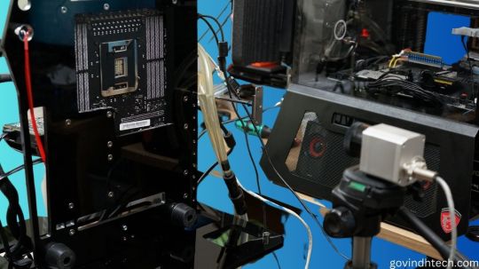
Test setup and measurements
We’ll acquire a simpler Socket 2066 motherboard, make a vertical benchtable, and test (or not). We’ll look at the sensor values and origins of the respective areas, and we’ll use the infrared thermal imaging camera to test the board’s heating around the socket and voltage converter for plausibility.
We can also record the heating process in time-lapse videos. We also want to know if motherboard hotspots or heat transfer damage other components.
For safe sensor readings and smooth test setup operation, we use the newest motherboard BIOS and HWinfo in the latest beta version from v5.53–3190 (click on beta version while downloading!). We fixed or deepened certain features after a deeper inspection, manufacturer check, and community suggestions.
The board’s CPU power supply has 5 1 phases controlled by an International Rectifier IR35201. This multi-phase buck controller supports Intel VR12 and evidently VR13. The so-called doubling allows two circuits per phase with five phases, relieving the individual VRMs and equalising hotspots in area. This chip’s voltages and currents will be discussed later.
Each control circuit uses one International Rectifier IR3555 voltage converter. These highly integrated power stage chips include gate drivers, high- and low-side synchronous MOSFETs, and the Schottky diode. Unlike other MOSFETs, they have analogue temperature sensors. How else can you accurately measure these voltage converters’ temperatures without an IR camera?
MSI employs the Nuvoton NC6795D as a Super IO chip on the tested motherboard to record and provide sensor information. With a central thermistor between the power stage chips, the voltage converters’ temperature is likewise measured. Thus, we choose the back measuring point below this thermistor for our video acquisition.
The coils and capacitors of these voltage converter circuits and the board temperatures up to the CPU are also checked.
Sudden shutdown and downclocking
To better comprehend the future testing and the concerns that were often addressed too polemically in forums, we must realise that motherboard makers use safety devices. The Skylake-X is clocked down to 1.2 GHz at exactly 105°C at the thermistor (HWinfo under line MOS, Nuvoton NCT6795D) by our test board until the temperature drops below 90°C. Only then does it reach full velocity.
This makes sense since the flash point for the PCB material (FR4) is much higher, but the maximum continuous operating temperature is only between 95 and 105°C to avoid dry-out, bending, and conductor path hairline cracks in multilayer PCBs. This is good because graphics card makers normally have more (unnecessarily) nerve in this area.
In Intel’s Extreme Tuning Utility (XTU), this downclocking termed Thermal Throttling: Yellow, yes. What about Motherboard VR throttling status indicators? We must also give a little addendum regarding HWInfo values. It is less well known that the IR35201 also measures temperature. These results for VR T1 and VR T2 are much higher and appear to contradict the external sensor.
As usual, only the controller chip temperature was output. This would be equivalent to voltage converter temperatures VRM1 and VRM2 on graphics cards with PWM controllers (AMD cards commonly utilised them) in various tools. Usually, the chip measured itself there. However, with IR35201 and IR3555, it can be presumed that the IR3555’s voltage values and temperature inside are also utilised.
Before the XTU yellow warns of motherboard VR throttling, these values are limited to 125°C and the CPU is clocked to 1.2 GHz. Because voltages could run outside specifications and damage hardware above 135°C, the motherboard is turned down without notice.
CPUs also protect themselves. Multiple integrated digital temperature sensors (DTS) determine the computing core and package temperatures. The precision of these calculations rises with temperature. Below 40°C, it’s irrelevant, but from 80°C, it’s accurate. We can also see that core and package temperatures can cause clock throttling.
The power loss of the IVR the CPU’s voltage converters that provide partial voltages is also included in package temperatures. With strong overclocking and manual voltage increase, unanticipated limit overruns might occur quickly, which not all tools can detect. So the CPU throttles without the user knowing why. The IVR will be discussed shortly.
0 notes
Text
An Analysis of DTMF Intercom Functionality | Application of SA809 RF Transceiver Module's DTMF Intercom in Access Control System
What is DTMF function intercom?
With the advancement of wireless technology, the security of access control systems has evolved beyond simple door control. The new generation of access control system solutions emphasizes both security and convenience. Features such as voice intercom and quick command operations are highly valued. Advanced access control systems can also be integrated with cameras and surveillance devices, enabling comprehensive security protection through interactive communication with the access control system using digital keypads. The latest access control solutions can be implemented using DTMF functionality for intercom purposes.

The DTMF intercom functionality allows users to send specific digital signals by pressing numeric keys on the transmitting end, which are then identified by the receiving end. This enables digital communication between users, such as calling on designated channels, sending specific commands for visitor verification, and facilitating remote door unlocking.

The SA809 series is a self-developed RF transceiver module by NiceRF, consisting of the SA809-TX RF transmitter module and the SA809-RX receiver module. The transmitter can be used with any analog intercom device with DTMF functionality, such as Motorola's GP338. The receiver decodes the signals received from the transmitter, performs verification, and then outputs high power through Mosfet. With a transmitting power of up to 5W, the SA809-TX ensures long communication distances, making it a cost-effective wireless remote control solution. Additionally, the SA809 can be customized based on specific customer requirements. It is produced and tested with strict lead-free technology, complying with RoHS and Reach standards.
Introduction to SA809 DTMF Intercom Solution:
The transmitter is equipped with DTMF functionality, and the module can transmit DTMF code signals of any length and any numeric combination when switched to PTT ON mode. Pressing any numeric key from 0 to 9 can trigger the DTMF transmission function once.

After the receiver is powered on, it enters the DTMF reception mode, and the output end controls the Mosfet to output a 3-second high-level signal. The receiver has a sensitivity of up to -124dBm, allowing users to achieve control over a distance of more than 5 kilometers in open areas using commonly available analog walkie-talkies with DTMF functionality.
The module internally uses a 1.5PPM TCXO crystal oscillator with a 25KHz bandwidth, ensuring stable frequency even with temperature variations. By connecting to a PC terminal, users can freely set frequencies ranging from 400MHz to 480MHz with a 25KHz interval, providing a total of 6400 channels. Additionally, combining the option to set 1-9 digit password combinations ensures the security and reliability of the system control.
How to configure SA809-Rx?

In conclusion, the DTMF intercom feature of the SA809 RF transceiver module not only enables remote unlocking in the access control system but also provides additional convenience through voice interaction and command transmission. The DTMF intercom feature enhances the functionality and flexibility of the access control system, further improving its security and convenience.
For details, please click: https://www.nicerf.com/walkie-talkie-module/wireless-switch-module-sa809-rx.html
For consultation, please contact NiceRF (Email: sales@nicerf.com).
0 notes
Text

New project! I just ordered this circuit board. Now I just hope that I have everything on there I need and didn’t forget anything…
This’ll be an 8x8x8 LED cube; you can find instructions on how to build these on Youtube, and I figured I wanted as well. Mine will be controlled by an STM32F030C8T6 (Reichelt still has some), and have Wifi connectivity via an ESP8266-01 module. It’s all largely designed around components that I either had laying around or wanted to play with, so this isn’t necessarily what I’d recommend for anyone else.
Other exceedingly technical details:
Internal voltage is 3-3.3 Volts; the case (plywood, not yet built) will have a barrel jack.
It’ll use 512 blue 5mm LEDs ordered from Aliexpress that should arrive any week now.
High side drivers are 74HC595 shift registers; I’m aiming for about 5-7mA per LED, so current shouldn’t be an issue (and I think the brightness is still okay). Each output controls one vertical column of LEDs.
Low side will be a bunch of N channel logic level MOSFETs whose name I’ve immediately forgotten again. Each output controls one horizontal layer of LEDs. Only one of them is going to be active at a time.
The shift registers and the low-level drivers are all addressed in parallel, for 16 (+2) data lines. Most instructions I’ve seen on the internet use a ninth shift register driving the low side transistors, and address all the shift registers serially, which saves on pins used–but I’ve paid for all of these pins, so I might as well use them. In theory that should allow for slightly faster updates, but I don’t think I’ll hit any issues there.
It’ll be controlled by custom firmware and a custom iPhone app that I’ve both written myself… as soon as I’ve gotten around to that.
Designed with KiCad 6. I used to use Eagle, but KiCad is more free (no Autodesk registration) and subjectively feels more pleasant.
I haven’t tested any of this yet, this is my first time using a Cortex MCU for anything, and it’s possible that this won’t work. Exciting!
The PCBs will take two weeks to arrive since I chose the cheaper option on Aisler, so I’ll update you then.
6 notes
·
View notes
Text
Factory of FUZZ (fuzz factory clone)
I’m always looking for the cheapest way to build pedals. I found these boards on OSH Park.com. Besides being a service for prototyping boards it’s also an open source repository of projects uploaded by the community. A board uploaded to OSH Park marked public can be ordered by anyone. The search function is not so great but it is searchable. I spent a day searching OSH Park for stompbox projects and found more than a few things that look worth building.
The OSH Park standard service is $5 per square inch with the requirement that you order three boards, and shipping is free. This usually cheaper than ordering boards from vendors but there is no support. One of the projects I found was a this Fuzz Factory. It looked well laid out and the cost was $7.75 for 3 boards, about $2.50 per board, which was pretty reasonable.
Order some of these boards here: https://oshpark.com/shared_projects/xaBILSTV. Check out my projects page for links to some OSH Park boards I designed. I have documentation here on my site.
With no build Docs you’re on your own. The Fuzz Factory is not a complex pedal and the schematic is readily available. Some OSH Park projects will link to documentation and other do not. This is a good way to level up your skills!
Getting Started
The Fuzz Factory is not a hard pedal to clone. The toughest part is wiring the pots. Getting a board where the pots mount directly to the board is a great help. Here three of the five pots mount to the board and two require off board wiring which makes a pretty easy build.
The Fuzz Factory has only a handful of parts. I soldered everything except the pots and the two germanium transistors. You’ll want to test a few transistors if you’re using germanium to get some that sound best. That said really everything even silicon can sound good in this circuit.
The Enclosure
For the enclosure I used a black powder coat 1590B from Tayda. For the logo and labels I milled the box using a desktop mill. The powder coat is removed to reveal the design. I created the design in Sketch on the computer exported some SVG files and loaded these into the mill.
Switching
I decided to try out a relay switching system. This uses a soft touch momentary SPST switch and some circuitry. I used boards from DIYGuitarPedals.com. Their system uses some discreet logic and a relay to handle switching and the status LED.
The PCB is designed to fit a 1590B or larger enclosure. It requires a few parts which are mostly easily available. The relay is available through Mouser. Erik over at DIYGuitarPedals was generous enough to send me two boards and the relays, thanks again Erik! Check out their web site and their YouTube channel.
The system uses a relay which is an electromechanical switch in a little box. The switch in this case is the RY9W-K. It’s a DPDT but rather than being engaged by a button or lever it’s engaging by an electrical voltage applied to a control pin.
In the picture below you can see the relay has 8 pins. The 6 pins on the left are the switching connections, each row is one switch, the center is the common connection that bridge to the outer connections depending on the state of the switch. Hey those six pins on the left are just like the pins on a regular DPDT switch-. The two pins on the right are the control and ground.
The board, relay, SPST switch, and other parts make up a single assembly that replace the 3PDT switches typically used for guitar pedals. You can see it neatly fits the lower bout of the 1590B enclosure.
Here is what the whole system looks like assembled. This is complete and could be dropped into any pedal replacing the standard blue 3PDT.
How does it work?
Unlike many relay systems that rely on a micro controllers this circuit uses only discreet logic. There are pros and cons to each. Using a micro controller requires some extra circuitry since the Micro Controller runs on 5v. They can be proprietary since someone has to write the software that runs the system. Using a Micro controller you can fit all the logic into an 8 pin DIP and add new features or up date the existing code. Using discreet logic your system can run on 9v, might have fewer parts, and won’t suffer from software bugs.
This system relies on the 4011 quad NAND gate to handle the switching logic. Check out this video for a more in-depth explanation of the switching logic.
youtube
Assembling the NAND Bypass board is pretty easy. Easier than making the Fuzz Factory board. It’s got very few parts and there is plenty of room to work. If you wanted to give this type of switching a try this would be a good place to start.
Building and wiring the Fuzz Face
The board mounts the three 10k pots and will accept 9mm or 16mm pots. If you are trying to fit this into a 1590B box in portrait orientation you’ll need to use 9mm pots! The two 5k pots are mounted off board. You could also build this in portrait with all 16mm pots.
I mounted the pots in the enclosure then soldered them to the board to make sure they were perpendicular to the enclosure.
I had some ribbon cable salvaged from an old computer. I used this to wire the off board 5k pots. The board marks the pins 1 and 3. Pin 1 also has a square pad. I used 16mm pots with pins that stick out perpendicular to the shaft. I cut a couple pieces strip board to interface the wires and the pots. This made for some nice clean wiring.
The bottom of the PCB is pretty close the corners of the enclosure. I’ll have to be careful it doesn’t short out there! This was a test fit. I needed to mark the positioning for the power, input and output jacks, then disassemble everything and drill these.
Once I got everything drilled I added some wires and reassembled everything. I realized I needed to move the two pots in the second row inboard a millimeter or two. You can see I had to file the holes a little.
I also installed the switching board. I stuck a little piece of wood to the side of the switch to brace it against the back of the enclosure. There was no way to brace the switch when tightening the nut.
You may have noticed the two germanium transistors are missing. Since these are notoriously inconsistent I decided I wanted to audition a few before selecting which would be used for this project. I have a bag of 40 I’ll test and measure these to find suitable pairs.
I have this TC1 Multi-function Tester. This cost about $17 on eBay. Well worth the money. It tests resistors, capacitors, diodes, transistors, and more. It will tell you all of the most useful information. It will also differentiate NPN, PNP, JFET, and MOSFET devices, and tell which pin is the base, collector, emitter, gate, source, or drain. Super handy.
Germanium transistors have a high degree of variation. Their hfe and leakage is very inconsistent across devices with the same part number. There is a lot of debate about what hfe values work best for different circuits. Some people like to judge by the numbers others like to use their ears. I’m going to go with a hybrid approach use the numbers to get in the ballpark and then audition by ear.
I measured all of the Germanium transistors in the parts bin, marked each with a number and made a spreadsheet of all the values I measured with the TC1.
https://docs.google.com/spreadsheets/d/10O7FYfs_f0x301CYvcvC7pWFFp8Ld2-e3oANXK-AOtc
This is a Fuzz Factory I built using a board from AionFX, it has a few extra knobs. I used sockets for the transistors. I figure I can plug some transistors into this to hear how they sound before soldering them into the new Fuzz Factories.
Here I wired up everything in the box. The NAND Bypass board is well laid out and labeled making wiring easy. Input and output jacks go to the input “In Jack” and “Out Jack” and the input and output from the PCB go to the “To PCB Input” and “To PCB Output”. It’s paint by numbers really!
At this point I gave it a test. I the LED worked, and bypass was working. So we’re goo to go. The last step is finding and installing some Ge transistors.
Tested some transistors in the green fuzz factory and decided on 1 and 9 from the spreadsheet. They had numbers that seemed to be the right range and sounded good.
Taco Fry Fuzz #1
The first us out of the way time to audition a couple more transistors and make the second box.
Tested a few more transistors and decided on #60 for Q2 70 hfe, and #21 for Q3 190 hfe. These sound good and we’re very close to the values for the first pedal. Which should make these sound very close.
What does it sound like?
The Fuzz factory is a highly variable fuzz. The sounds range from standard distortion to fuzz into high gain. It’s possible to dial in gated fuzz and zipper sounds. Not all of it useful in many cases. It’s all fun and inspiring.
youtube
Factory of FUZZ (fuzz factory clone) was originally published on Super-Freq
2 notes
·
View notes
Text
Manufacturing Industrial Robots
Automate repetitive duties and take the ergonomic pressure off staff with an array of commercial robots from Raymond and Bastian Solutions. Talk to us about customizing an answer to help streamline your distinctive pallet assembly and disassembly purposes. Just because the name suggests, cylindrical robots have a cylindrical work area. They function a robotic arm that's connected to a base via a single joint, with one more linear joint connecting the arm’s links visit site.
A second type of singularity in wrist-partitioned vertically articulated six-axis robots occurs when the wrist middle lies on a cylinder that is centered about axis 1 and with radius equal to the gap between axes 1 and four. Some robot manufacturers also mention alignment singularities, the place axes 1 and 6 turn into coincident. When the robotic passes near a shoulder singularity, joint 1 spins very fast. Repeatability is usually crucial criterion for a robotic and is just like the concept of 'precision' in measurement—see accuracy and precision. ISO 9283 units out a method whereby both accuracy and repeatability can be measured.

Many of probably the most oppressive and routine workplace chores—those that are dirty, dull, or dangerous—are now entirely within the robot realm. But because of current technologic advances, robots are also handling more complex operations that require extreme precision. For example, robots with laser-vision techniques can match doorways exactly to automotive bodies. These improvements, combined with several financial forces, are prompting companies to contemplate industrial robots extra significantly. The Silver Arm was created by MIT's David Silver to perform exact meeting using contact and stress sensors and a microcomputer.
Collaborative and traditional industrial robots © IFR International Federation of Robotics For more data, please refer to the IFR Positioning Paper on Demystifying Collaborative Robots and case studies. FANUC’s new SCARA robots are ideal for high-speed, precision applications corresponding to meeting, pick and place, testing/inspection, dispensing and packaging processes. It may be that when informed to go to a sure X-Y-Z place that it gets solely to inside 1 mm of that place. But if that position is taught into controller reminiscence and each time it is despatched there it returns to inside zero.1mm of the taught place then the repeatability will be inside zero.1mm. The cylindrical coordinate robots are characterised by their rotary joint at the base and a minimal of one prismatic joint connecting its hyperlinks.
How the robot interacts with other machines within the cell should be programmed, each with regard to their positions in the cell and synchronizing with them. Power source – some robots use electric motors, others use hydraulic actuators. Nowadays, it is extremely unlikely to see any hydraulic robots available in the market.
The automotive manufacturing industry has long been one of many quickest and largest adopters of commercial robotic expertise, and that continues to today. Robots are used in nearly each part of automotive manufacturing in one way or another, and it stays as one of the most highly automated supply chains on the planet. The report was produced as part of the MIT Work of the Future initiative. Worker resistance has not seemed to play an enormous role in slowing adoption of business robots, according to MIT.
This company developed a robot to complete a spray painting utility and finally turned ABB. This is only one example of when giant companies began to develop their own industrial robots. The first prototype, Unimate, was produced in 1961 and put in in GM's factory for die casting dealing with and spot welding.
The most deployed kind of robots within the manufacturing sector include gantry robots, which move alongside a single axis, and SCARA robots, which are able to shifting alongside three axes. Among the most recent types of robots, both exoskeletons and collaborative robots are designed to work in close proximity to people. Infineon’s components and system options are properly suited for industrial robots as a whole. Power digital elements, similar to IGBTs and CoolSIC™ MOSFETs, including becoming EiceDRIVER™ gate driver options throughout varied energy ranges, help a extensive range of robotic payloads. CoolMOS™ and CoolSIC™ MOSFETs, and auxiliary power supply solutions corresponding to CoolSET™ allow energy management.
However, they'd zero external sensing and were used for easy tasks such as pick and place. Spot welding joins two contacting metal surfaces by directing a big present via the spot, which melts the steel and forms the weld delivered to the spot in a really quick time . How sensible, connected robots are reworking manufacturing © IFRFor extra info, please check with the IFR Information Paper on How Connected Robots are Transforming Manufacturing.
This means they can produce high-quality products with little variation and greater consistency than their human counterparts. Here is a brief overview of how robotics in manufacturing are being used to vary the industry panorama by increasing productivity and precision while defending staff from unsafe working environments. With greater than 250 software features for enhanced intelligence, motion, safety and productiveness and a wide variety of FANUC high quality accessories, we now have an answer for almost every conceivable utility. The area of commercial robotics may be extra virtually outlined as the study, design and use of robotic techniques for manufacturing (a top-level definition counting on the prior definition of robot).
FANUC robots are easy to function and supply full flexibility due to a variety of application-specific choices, easy integration, payloads up to 2,300kg and most reaches as much as 4.7m. Fully autonomous robots in manufacturing are generally needed for high-volume, repetitive processes — where the speed, accuracy and sturdiness of a robot provides unparalleled advantages. Other manufacturing automation solutions include robots used to assist folks with extra intricate tasks. The robot executes elements of the method corresponding to lifting, holding and shifting heavy items. As extra companies are seeing the worth of robotics, the variety of industrial robots installed worldwide is estimated to extend to 2.6 million units by 2019.
When it involves purchase concerns, component price is mostly not a high concern when firms are shopping for finish effectors. This is very true for automotive OEMs that will incur high interruption prices if their production strains are down. Since grippers and EOATs account for around three % of the total value of automation, the choice of a high-priced provider will have relatively little influence on a company’s production-line prices.
Automation in manufacturing is extremely cost-effective for corporations of all sizes. Rather than outsourcing jobs abroad, smaller corporations can use robots to perform chosen tasks at a decrease price and with greater quality results than with outsourced workers. This may be stunning, since smaller manufacturing companies may assume that buying robotics is an costly funding. While the preliminary price could also be steep, the advantages can save manufacturers hundreds of dollars in reduced costs and improved productiveness.
Automation was achieved using punched paper tape to energise solenoids, which would facilitate the movement of the crane's control levers. The variety of motor revolutions required for every desired motion was first plotted on graph paper. This info was then transferred to the paper tape, which was also driven by the robotic's single motor. They are one of many first robots to have been used in industrial functions. They are commonly used for machine tending in die-casting, plastic injection and extrusion, and for welding. While there are many robotic functions to select from inside the industry, there are 6 that stand out as the most common and most precious purposes available on the market.
Accuracy may be improved with exterior sensing for example a vision system or Infra-Red. Accuracy can vary with velocity and position within the working envelope and with payload . This could additionally be outlined when it comes to the angular or linear velocity of every axis or as a compound pace i.e. the velocity of the tip of the arm when all axes are shifting. Delta robots are particularly helpful for direct control tasks and high maneuvering operations (such as quick pick-and-place tasks).
Concurrently, the robotic retains inventory on missing, mispriced or misplaced stock. But sooner or later, autonomous robots will work in all aspects of retail, from the warehouse to supply. These robotic arms can have a mess of sensors and imaginative and prescient systems able to viewing photographs to help with their computer-based control. That sensor and imaginative and prescient feedback can be utilized with with synthetic intelligence to make choices about the conduct of the robotic arm.
Alex Owen-Hill is a contract author and public speaker who blogs about a massive range of topics, together with science, presentation expertise at CreateClarifyArticulate.com, storytelling and robotics. He completed a PhD in Telerobotics from Universidad Politecnica de Madrid as part of the PURESAFE project, in collaboration with CERN. As a recovering academic, he maintains a firm foot in the robotics world by running a blog about industrial robotics. This is necessary because it allows producers to maintain their operations in the U.S and still compete within the world market. In reality, automation is changing into increasingly necessary for firms who wish to create more jobs in the U.S and stay competitive.
They may make the most of various sensors to help the robotic system in finding, handling, and positioning products. Industrial robotics took off quite rapidly in Europe, with each ABB Robotics and KUKA Robotics bringing robots to the market in 1973. ABB Robotics introduced IRB 6, among the many world's first commercially available all electric micro-processor managed robotic. The first two IRB 6 robots have been bought to Magnusson in Sweden for grinding and sprucing pipe bends and were installed in production in January 1974. Also in 1973 KUKA Robotics constructed its first robotic, known as FAMULUS, additionally one of the first articulated robots to have six electromechanically pushed axes.
Typically a robotic is shipped to a taught place numerous occasions and the error is measured at every return to the position after visiting 4 other positions. Repeatability is then quantified using the usual deviation of these samples in all three dimensions. A typical robotic can, after all make a positional error exceeding that and that might be a problem for the method. Moreover, the repeatability is completely different in different elements of the working envelope and likewise changes with velocity and payload. ISO 9283 specifies that accuracy and repeatability should be measured at most pace and at maximum payload. But this results in pessimistic values whereas the robotic could probably be rather more correct and repeatable at light hundreds and speeds.
youtube
1 note
·
View note
Text
Moisture sensor -V2
The V1 version of the moisture sensor has now been trialed and is delivering good data. The remaining challenges are to reduce power consumption as much as possible and make a better board and container.
Running the sensor every 5 minutes shows that if the refresh rate is reduced to, say, 4 times a day, battery life should be good for a couple of months. However this test has only included the current draw when awake and sending; it minimises the quiessant current draw which will be much more significant over months.
SIM cards
I’ve tried several now and concluded that it is the setup cost per card which is the main cost. Both the COOP and GiffGaff have non-recurring PAYG accounts which cost about 10p/Mb . Each HTTP Post takes about 2k so at low data rates, this cost is insignificant. Both have a minimum top-up of £10 providing 5-10 GB of data, so these are fine for the occassional project. Thingsmobile is half that price to set up, can run multiple SIMs off the same account and would be best for a batch of devices.
Batteries
I bought some 18650 Li-ion batteries - 2 * 4200mAh for £10 - much cheaper than the LiPo battery £10 / 1500mAh. I’m not sure Im getting them fully charged with a cheap charger and need better.
Aerial
The aerial connector is rather fagile and needs care in connecting and discnnecting - there is some advice here https://learn.sparkfun.com/tutorials/three-quick-tips-about-using-ufl
The improved aerial does give a stronger signal .
LoRAWAN
This would be preferable to GSM and there were plans for a network in Bristol. There area few stations shown on this site
https://www.thethingsnetwork.org/community/bristol/
but sadly the project seems defunct.
Multiple Temperature sensors
It would be interesting to see how air temperature, which affects the respiratior rate from the tree ) compares with the ground temperature and another temperature sensor woul add little cost or power consumption ( 4mA when running) to the project. The One-wire protocol supports multiple serial sensors with a single pull-up resistor.
GPIO power
The main design change from V1 is to use a GPIO pin to supply the current for the sensors. I’d assumed that in deep-sleep the 3V3 pin would be off but in fact it’s on all the time, and although the sensors don’t draw much, its better to turn them on only when needed. They need a few hundred ms to stablize before reading. The moisture sensor draws 5 mA but being capacitive, it will draw more on startup (thanks Michelle Ben for alerting me to this issue). The Temperature sensors draw no more the 4mA but this adds up to 13mA for two. Tests show that the moisture sensor and one temp sensor run OK off one GPIO but it makes more sense to use the GPIO to trigger a MOSFET switch to power all three sensors and this wil be version 3.
Wiring and enclosure
My big problem is with the wiring. I decided to use 3 pin JST connectors for the sensors so they could be swapped. I will add another sensor for air temperature. I bought a kit to make up my own plugs but the tiny terminals defeated me and I bought some ready wired. Batteries can be exchanged in the battery pack.
The problem is how to wire it all up. Whilst it runs when wired with jumpers:

the veroboard shows just how hopeless my soldering is : no detectable bridges but it doesnt work and its tricky to wire to the right pins - I need a headset!


Later
I got the v2 board working at last thanks partly to encouragement from my Bristol Hackspace collegues. I made a parallel lashup with a breadboard - the TTGO chip is too big to fit a breadboard so I used the breadboard for the additional wiring with jumpers from the required pins and its easy to wire into the JST plugs; made sure that worked; cleaned up all the solder, checked for bridges and then slowly added each wire, testing as I went for bridges and that it worked with a second TTGO board. Still so easy to get bridges. And I have a head magnifier on order.

1 note
·
View note
Link
Please watch: "LED chaser using transistor BC547 || 2 transistor LED blinking" https://www.youtube.com/watch?v=pWTy77lQzMA --~-- diy 3.7v to 40v volt boost converter !! DC TO DC converter 3.7v to 40v led driver ne555 3.7v থেকে 40v ভোল্টের বুস্ট কনভার্টার ডায়ি 3.7v to 40v volt boost converter DC TO DC converter ! 3.7v to 40v led driver #3.7vto40v #voltboostconverter #dctodcconverter 1 mosfet irf 3205 2 104pf 3 diode 4 capacitor 220UF 160V 5 VR10K 6 IC NE555 7 copper coil 8 pcb Electronics BD circuit projects,circuit board,science project,school project,do it yourself projects,boost converter,simple boost converter,simple boost converter 555,boost converter circuit using 555,boost converter circuit diagram,voltage booster circuit,voltage booster,voltage booster dc,voltage booster circuit diagram,voltage amplifier circuit diagram,voltage,diy,voltage amplifier circuit,boost converter circuit,voltage multiplier,dc to dc converter How to Make 3.7v to 5v Converter Circuit-_- Dc to Dc Convent 3.7v Li-Ion 18650 Battery charger using LM2596 DC-DC buck converter | single battery How to make 3.7v to 5v Converter circuit | DC To DC Boost Converter. DIY 3v To 12v Boost Converter Circuit | DC To DC Converter How to make 3.7v to 5v Converter circuit | DC To DC Boost Converter. Dc to dc boost converter 4v dc to 140v dc My testing booster 3.7V to 12V-13.7V DC converter facebook https://www.facebook.com/md.hridoykhan.353803 twitter https://twitter.com/mdnasir72351844 in https://www.linkedin.com/feed/?trk=onboarding-landing instagram https://www.instagram.com/mdnasir8748/ led chaser https://www.youtube.com/watch?v=pWTy77lQzMA&t=16s vumeter https://www.youtube.com/watch?v=wzbD_bYj1Hg
1 note
·
View note
Text
Technically Speaking.
Not that rare for me to roll my eyes when a reviewer or sales person tries to explain a technical thing and blows it.
Hey I am not an electrical engineer, but that was only one and a half years difference in my university education and I did hang with a few. For that I do know a MOSFET from a Bipolar and what a Farad is. I can solder. I know my limits and can see where other people exceed theirs.
I watched a you tube review by this stern person from TAS about a new (expensive) Technics Integrated Amplifier. He was quite a ways out of his depth and went on for some time explaining what he remembered about what someone told him.
The power end is a Class D amp. Everything seems to be now. Trick is about everything else is digital.
I wish he had just stayed in his lane and said how it sounded. Apparently very good. It is one box, handsome, not cheap by any means, but reachable. If I had a small place I would be happy with this a turntable and my invisible speakers. Yes it has a phono input.
He missed or ignored or failed to notice one very cool thing. All speakers have not flat impedance curves. One thing impedance can do is mess up the phase of signals in the Bass. Volts will peak before or after the current so depending on the type of amplifier it has one or another type of trouble. Phase is important low down as that is where you are most sensitive to it. Higher up you would never know. He does mention how good the Bass is.
What this thing can do is really cool. You can read about it on Technics website as I did. This amplifer can send a test signal to your speakers and calibrate their impedance. It then can adjust the phase of the signal to keep it coherent. The effect in the Bass is more accuracy and clearer. That can be done as it has internal DSP that lets the machine fiddle. Digital has its advantages.
There is another version of this thing that does not have an MC preamp and just a MM. That one is called the SU-G700. It is less expensive.
Both versions are economy versions of an ICON product. It seems when huge multi-billion dollar companies want to show off they really can. Little guys working in sheds in the Cotswolds cannot keep up stamp their feet as they may.
Of course that means there is a bigger one. Dear dear.
0 notes