#how to check mosfet
Explore tagged Tumblr posts
Visit Tumblr Blog
Explore Tumblr blogs with no restrictions, modern design and the best experience.
Last Seen Tumblr Blogs


Fun Fact
Users from the US are the majority of Tumblr visitors.
Text
Mosfet Testing......
#working #mobile #repair #mobilephone #mobilerepair #mobiles #mosfet #mobilephonerepairspecialist #MOSFET #mobicationhub #mobicationhub9509959090 #testing #mobilerepairtools #iPhone #androidrepair
#mosfet testing#mosfet#how to test mosfet#mosfet transistor#mosfet testing with multimeter#how to check mosfet#how to check mosfet with multimeter#easy method of testing mosfet#how to test mosfet using multimeter#n channel mosfet#smd mosfet testing#how to test mosfet with multimeter#how to test a mosfet#test mosfet#n channel mosfet testing#mosfets#mosfet test#mosfet explained#easy way to test mosfet#p channel mosfet testing#mosfet tutorial
0 notes
Text
Pontificate
VERB
express one's opinions in a way considered annoyingly pompous and dogmatic.
Yah OK that is me (sometimes?). Though it is a common thread in the audio hobby. Tribes form and hold fast to their dogma. You know how that works. Tubes are best. MOSFETs are best. Give me Single Ended Triodes, or give me death. At the head of these tribes are annoyingly earnest people. Only they are right, all others are misguided.
My tribe is vinyl is best. Linear tracking turntables are the best. ARC Preamps ...... well you get the idea. I am pretty open about other things. Any amplifier technology that works is OK in my books as long as we have triple digit Watts on tap and some damping factor.
The most egregious pontificators are the golden ears with YouTube channels and or magazine columns. I find them entertaining especially when they miss things or just go far down some rabbit hole. That is why I check them out so often.
Take for example a person reviewing a speaker. There are so many methods, techniques, and design philosophies that your head will spin. Whichever speaker on review is very good to the best (depending). That Audiophiliac guy has had 60 year old Klipschs and bi-polar planars and baffleless cones, and boxes and well everything as his go-to reference at one time or another. He has interviewed speaker designers and praised their work while keeping completely different types as his reference.
Thing is I have a problem with contradictions. If one way is best the others are not. For example PS audio makes a speaker range that has an exotic diaphragm based treble driver that is the end result of years of work. In many respects it is the child of one of the early speaker design gods Arnie Nudell of Infinity fame. It is apparently VERY good.

BUT there are competing designs by Wilson Audio which is by many people considered the GOAT but uses fairly conventional magnetic coil based drivers. Many of them very carefully tuned but still box based.

The trick here is the position of the drivers can be adjusted to exactly align with your head-in-a-vice listening position.
Then you have electrostatics and planar magnetics and on and on.
So which approach is the best?
Those guys above are both are not inexpensive and have quite divergent design philosophies. So actually neither can be best.
I am certain they both sound very good with well matched equipment and room treatment. The room has to be "tamed" to work with these guys.
Any speaker can sound good within limits. Many sound very good even with flaws that someone from another tribe would consider fatal.
I do not like speakers that blow sound out front and back. I built those and was happy, but very much of what you hear is not in the source. It is an effect that muddles the sound. It is sound waves bouncing off back walls and other surfaces. Your brain compensates for that. I now prefer to minimize brain compensation.
Clarity and wide frequency range are my thing. Clarity means a minimum of extra sound waves coherently produced. Wide range means deep bass, and well my high frequency is not what is once was, but I have measured response way over my ear's limit.
If you sit in close to the "good" spot and cannot even identify where the speakers are that is good. You just want a curtain of sound an illusion of something or even somewhere else stretched across the room. That is the true goal. If you have that you are there already.
I recall a golden ear saying that a particular tube amplifier had very little "tube fuzz". I supposed that meant he heard it often, but forgave the other devices that flaw. "Solid State detail" was another thing he said. So SS has more detail? I recall another questioning MOSFETs as having a particular not quite right characteristic. Of course very many think that old school Bipolar transistors are fundamentally wrong for not quite clear reasons.
I could go on for hours about phono pickups. I may have once or twice, but I have some wise men on my side.
It all falls down to my mantra. There is no best. Better is what you like. If you like something more it is better.
2 notes
·
View notes
Text
VNI4140K Specifications & Features Explained
The VNI4140K is a cutting-edge high-side smart power switch designed for industrial and automotive applications. But what makes it special? Why should engineers and tech enthusiasts care about it? This article dives deep into its specifications, features, and applications, making it easy to understand—even for those unfamiliar with complex electronic components.
What is the VNI4140K?
The VNI4140K is an intelligent quad high-side power switch designed to handle loads with enhanced safety and efficiency. It integrates various protection features, making it ideal for automotive, industrial, and smart control applications.
Key Features of the VNI4140K
Quad-channel high-side switch
Over-temperature protection
Short-circuit protection
Overvoltage clamp
Low power consumption
Diagnostic feedback for fault detection
Technical Specifications
Operating Voltage: 8V – 36V
Maximum Load Current: 2A per channel
On-Resistance (Rds ON): 0.1Ω (typical)
ESD Protection: Yes (IEC 61000-4-2 compliant)
Temperature Range: -40°C to 150°C
Package: PowerSSO-36
Pin Configuration and Functions
The VNI4140K comes in a PowerSSO-36 package with dedicated input, output, and diagnostic pins. Key pins include:
VCC: Power supply input
IN1-IN4: Control inputs
OUT1-OUT4: Output channels
GND: Ground
FAULT: Diagnostic feedback
How the VNI4140K Works
The VNI4140K acts as a smart electronic switch, replacing traditional mechanical relays. It uses MOSFET technology to efficiently control high-current loads while offering built-in safety features. The fault diagnostics system detects and prevents issues like overheating or short circuits.
Advantages Over Traditional Switches
Improved Energy Efficiency: Consumes less power compared to mechanical relays.
Enhanced Durability: Solid-state design minimizes wear and tear.
Faster Response Time: Reacts quicker to input signals.
Integrated Protection Features: Prevents circuit damage due to overcurrent or overheating.
Common Applications
The VNI4140K is widely used in:
Automotive electronics (lighting systems, door locks)
Industrial automation (motor controls, PLCs)
Smart home devices (intelligent power management)
Medical equipment (precision switching for diagnostics and monitoring devices)
Installation and Usage Guidelines
Ensure proper heat dissipation to prevent overheating.
Connect the diagnostic pin to a microcontroller for real-time monitoring.
Use appropriate filtering capacitors to stabilize the power supply.
Avoid exceeding maximum load limits to prevent system failure.
Troubleshooting and Maintenance Tips
Overheating? Ensure proper ventilation and heat sinks.
No output signal? Check control input voltage.
Short circuit detected? Inspect load connections and wiring.
Intermittent operation? Test for voltage fluctuations.
Conclusion
The VNI4140K is a powerful and reliable quad high-side smart switch designed for various industrial and automotive applications. With advanced protection features, low power consumption, and efficient performance, it offers significant advantages over traditional switching solutions. Whether you're an engineer or a tech enthusiast, understanding its specifications and features can help you integrate it effectively into your designs.
0 notes
Text
Search valued Stereo power amplifier to experience complete streaming requirements
Do you want to achieve better sound in your music and audio signals? However, gaining this outcome is not easy for everyone, as some music devices only perform audio functionality for a while. If you face a low audio facility, then you go ahead with technological advancement. So, you must confirm your goal and try to audio better through using amplifiers. Throughout the marketplace, you come across many amplifiers. But you need more certainty about how to add sound.
Refrain from making the decision to buy a power amplifier. Instead, take a brief review and analysis to see how much it improves overall performance in your self-prepared game series. As it converts the power signal into a higher one, sufficient improvement in your live streaming is about to happen. No matter what power amplifier you use, it is the part of the subwoofer speaking system that is concerning.
What do you expect from a power amplifier?
Using the fine-grade amplifier makes you quite close to enhancing sound quality. After all, you must experience a better sound experience regardless of operation. But, you have the technical expertise to reach one conclusion to select the best amplifier name. So, you should keep key points in mind when choosing the best version of the stereo power amplifier. It must contain the signal gain, efficiency, and output power.
If the numerical value of one amplifier is greater than the other, consider the next one. The overall strength of the Power amplifier is measured in watts. The high watts indicate that they have been strengthened more. If you have to purchase the best quality amplifier, then you focus on its characteristics. Let us check how Amp IV can seem better than general-purpose power amplifiers.
Characteristic of Amp IV
Dual Mono Reference Power Amplifier
High damping factor availability for controlling the speaker
20 selected MOSFET output transistors
WBT loudspeaker terminal
Professional protective circuit
Voltage gain 250 DB
When you connect with a media-rich industry, you are in the prime of distributing multiple audio systems according to your needs. After that, app-based functions are quite helpful for distributing music on a wide range of Wi-Fi networks. Using the streaming amplifier, transforming network music is not difficult even though there is no multiple-box availability.
Keep your audio quality up-to-mark according to your business. But, you need the sure affirmation to end your search at which destination. While settling business in Germany, you can search Germany made audiophile speakers to achieve a fruitful sound quality experience. The sound quality should be such that it does not compel the listener to leave your streaming due to low pitch audio. No matter what audiophile component you require, our destinations are equipped with all the components to fulfill your needs. Visit our website to get the Amplifier details.
YouTube channel link: https://www.youtube.com/@accusticarts955
youtube
#audio power amplifier#power amplifier online#stereo power amplifier#germany made audiophile speakers#power amplifier amp iv#stereo pre amplifier#Youtube
1 note
·
View note
Text
Troubleshooting Common Issues In SMPS Designs

Despite their benefits, switched-mode power supplies (SMPS), which efficiently convert electrical power switching between different energy levels, can have a number of design flaws. During design, development, and operation, SMPS may run into a number of issues like component failure, excessive noise, overheating, and instability. To ensure dependable and effective functioning, it is crucial to comprehend these issues and know how to resolve them. This blog includes a thorough analysis of typical difficulties with SMPS designs as well as practical solutions for their diagnosis and troubleshooting.
Common issues in SMPS designs
Common issues in SMPS designs can significantly affect performance and reliability.
Instability and oscillation: A fluctuating or oscillating output voltage and insufficient control are common indicators of instability and oscillation. These problems are usually caused by inadequate phase margin, an inadequate compensation network, or a poorly designed feedback loop. In order to debug, the feedback loop needs to be appropriately built with a phase margin, and the stability of the loop properly analyzed using simulation tools. The components of the compensation network need to be checked, and the values of the resistors and capacitors need to be altered as necessary. To find instability situations and make necessary design adjustments, the loads need to be tested.
Excessive noise and EMI: High levels of electromagnetic interference or audible noise from the SMPS might be signs of excessive noise and EMI. Poor PCB layout, insufficient filtering, or rapid switching transients are frequently the cause of this. The PCB layout needs to be optimized to reduce loop regions and stable ground planes need to be provided in order to solve these issues. By employing the right capacitors and inductors and by improving or adding input and output filters, filtering can be improved. To manage switching transients and lower noise, soft switching strategies and snubber circuits must be used.
Overheating: Thermal shutdowns and overheated components, including switching transistors and diodes, are frequent signs of overheating. This may be the consequence of inadequate thermal management, high power dissipation, or inadequate cooling. Cooling must be improved by installing fans, heatsinks, or better airflow to address overheating, and enough ventilation must be available. To minimize power dissipation, components with reduced on-resistance should be chosen. For optimal heat transmission from heated components to heatsinks or the chassis, thermal pads and conductive materials must be used.
Component failure: The SMPS may malfunction or behave erratically as a result of a component failure; frequently, observable damage to parts like capacitors, transistors, or inductors is present. Overvoltage or overcurrent situations, subpar or underestimated components, and high operating stress are common causes. Multimeters and oscilloscopes must be used to find electrical problems and components should be physically checked for damage as part of the troubleshooting process. To avoid stress and failure, outdated components with higher voltage and current ratings should be replaced, and heat, overcurrent, and overvoltage safety circuits should be installed.
Poor efficiency: High power loss and excessive heat generation might result from inefficient operation. Suboptimal design, excessive conduction losses, or ineffective switching are frequently the causes of this problem. Using high-efficiency MOSFETs and considering synchronous rectification can increase efficiency. By utilizing low-resistance components and making sure that PCB trace design is correct, gate drive circuits can be optimized to minimize switching losses and reduce conduction losses. To improve overall efficiency, the complete SMPS design should be reviewed and optimized, taking into account topology, component selection, and thermal management.
Diagnostic tools and techniques
The ability to detect and fix problems with SMPS designs efficiently depends on the use of diagnostic tools and procedures.
Oscilloscope: Because it enables engineers to detect ripple and noise levels on the output, measure voltage and current waveforms, analyse switching transients and noise, and diagnose SMPS issues, an oscilloscope is a critical diagnostic tool. An oscilloscope aids in identifying problems with signal integrity and stability by giving an image of electrical signals.
Spectrum Analyzer: For the purpose of locating electromagnetic interference (EMI) problems, a spectrum analyser is essential. It quantifies electromagnetic emissions, breaks down noise into its frequency components, and evaluates how well shielding and filtering work. This tool facilitates the identification of EMI sources and the assessment of the interference-mitigating effectiveness of the design.
Thermal Camera: Thermal management in SMPS designs may be evaluated with the use of a thermal camera. It assesses the efficacy of cooling methods, visualises temperature distribution, and finds hotspots. A thermal camera helps to avoid component overheating and optimise cooling techniques by detecting locations of excessive heat.
Multimeter: Finally, for simple electrical measurements, a multimeter is a useful instrument. It monitors voltages and currents, verifies component values like capacitance and resistance, and detects open or short circuits. Its functionality is crucial for confirming that parts are operating correctly and finding fundamental electrical problems with the SMPS design.
Effective diagnostic tools and a complete understanding of the underlying causes of typical difficulties in SMPS systems are required for proper troubleshooting. It is important to tackle issues related to instability, noise, overheating, component failure, and low efficiency to guarantee dependable and effective functioning. Significant improvements in SMPS performance and reliability may be achieved by using the right diagnostic tools and following best practices in design and testing. Improving SMPS designs requires constant learning and modification as technology develops. Coming to technological development, Miracle Electronics is a well-known SMPS transformer manufacturer in India, whose proficiency in creating dependable and technologically-advanced transformers guarantees best-in-class efficacy and longevity for a wide range of applications. Miracle Electronics provides solutions that satisfy the strict specifications of contemporary electronic systems, increasing efficiency and dependability in every design.
Resource: Read more
0 notes
Text
The Best Skylake-X CPUs Motherboards

TIM gate, VRM disaster? Possible X299 motherboard faults and Skylake-X
In recent weeks, the leaf and video forest has been quiet. Even a VRM disaster or TIM gate (hot paste instead of lot) were discussed, but if you examine closely, the G… Thermal paste instead of solder Intel’s choice of improper (but cheaper) thermal paste instead of indium-based solder contributes to the cooling issue. Discuss the shelf life now… Default Settings Outside the Box, Cheats, Heat Long before launch, motherboard manufacturers made the first critique.
A typical all-in-one compact water cooler has dozens… We hold motherboard makers accountable. Blaming the imminent heat inferno just on Intel and the CPU cranked to its maximum limit would have been too short-sighted.
Noise across all media has been scarce in recent weeks. There was even discussion of a VRM disaster or TIM gate (thermal paste instead of solder), but the whole thing is just a long causal chain that starts with a hot-headed CPU. In theory, there are three. We try to make it simple, so one after another.
(1) Skylake-X is hardly coolable out-of-the-box in typical use due to excessive power consumption and thermal paste that limits optimal heat dissipation.
(2) The average user has little overclocking room, and many motherboards limit the CPU owing to design issues like insufficient external voltage converter cooling. Extreme overclockers barely work with modern hardware.
Usually, too much rhetoric is added, which doesn’t do credit to the potential purchasers’ difficulties.
Test setup and measurements
We’ll acquire a simpler Socket 2066 motherboard, make a vertical benchtable, and test (or not). We’ll look at the sensor values and origins of the respective areas, and we’ll use the infrared thermal imaging camera to test the board’s heating around the socket and voltage converter for plausibility.
We can also record the heating process in time-lapse videos. We also want to know if motherboard hotspots or heat transfer damage other components.
For safe sensor readings and smooth test setup operation, we use the newest motherboard BIOS and HWinfo in the latest beta version from v5.53–3190 (click on beta version while downloading!). We fixed or deepened certain features after a deeper inspection, manufacturer check, and community suggestions.
The board’s CPU power supply has 5 1 phases controlled by an International Rectifier IR35201. This multi-phase buck controller supports Intel VR12 and evidently VR13. The so-called doubling allows two circuits per phase with five phases, relieving the individual VRMs and equalising hotspots in area. This chip’s voltages and currents will be discussed later.
Each control circuit uses one International Rectifier IR3555 voltage converter. These highly integrated power stage chips include gate drivers, high- and low-side synchronous MOSFETs, and the Schottky diode. Unlike other MOSFETs, they have analogue temperature sensors. How else can you accurately measure these voltage converters’ temperatures without an IR camera?
MSI employs the Nuvoton NC6795D as a Super IO chip on the tested motherboard to record and provide sensor information. With a central thermistor between the power stage chips, the voltage converters’ temperature is likewise measured. Thus, we choose the back measuring point below this thermistor for our video acquisition.
The coils and capacitors of these voltage converter circuits and the board temperatures up to the CPU are also checked.
Sudden shutdown and downclocking
To better comprehend the future testing and the concerns that were often addressed too polemically in forums, we must realise that motherboard makers use safety devices. The Skylake-X is clocked down to 1.2 GHz at exactly 105°C at the thermistor (HWinfo under line MOS, Nuvoton NCT6795D) by our test board until the temperature drops below 90°C. Only then does it reach full velocity.
This makes sense since the flash point for the PCB material (FR4) is much higher, but the maximum continuous operating temperature is only between 95 and 105°C to avoid dry-out, bending, and conductor path hairline cracks in multilayer PCBs. This is good because graphics card makers normally have more (unnecessarily) nerve in this area.
In Intel’s Extreme Tuning Utility (XTU), this downclocking termed Thermal Throttling: Yellow, yes. What about Motherboard VR throttling status indicators? We must also give a little addendum regarding HWInfo values. It is less well known that the IR35201 also measures temperature. These results for VR T1 and VR T2 are much higher and appear to contradict the external sensor.
As usual, only the controller chip temperature was output. This would be equivalent to voltage converter temperatures VRM1 and VRM2 on graphics cards with PWM controllers (AMD cards commonly utilised them) in various tools. Usually, the chip measured itself there. However, with IR35201 and IR3555, it can be presumed that the IR3555’s voltage values and temperature inside are also utilised.
Before the XTU yellow warns of motherboard VR throttling, these values are limited to 125°C and the CPU is clocked to 1.2 GHz. Because voltages could run outside specifications and damage hardware above 135°C, the motherboard is turned down without notice.
CPUs also protect themselves. Multiple integrated digital temperature sensors (DTS) determine the computing core and package temperatures. The precision of these calculations rises with temperature. Below 40°C, it’s irrelevant, but from 80°C, it’s accurate. We can also see that core and package temperatures can cause clock throttling.
The power loss of the IVR the CPU’s voltage converters that provide partial voltages is also included in package temperatures. With strong overclocking and manual voltage increase, unanticipated limit overruns might occur quickly, which not all tools can detect. So the CPU throttles without the user knowing why. The IVR will be discussed shortly.
0 notes
Text
All about Analog Layout Design - Maven Silicon
Analog layout design is a critical aspect of integrated circuit (IC) design that involves translating abstract circuit schematics into tangible silicon layouts. This discipline is vital for optimizing performance, reducing noise, and ensuring the manufacturability of high-performance analog and mixed-signal ICs.
Candidates in this course will learn Linux, EDA tools, and physical verification checks like LVS and DRC. They'll tackle sub-micron process challenges like Lachup, Antenna, EM, and IR drop. Completing the Analog Design course equips candidates to contribute to cutting-edge IC development and confidently participate in the process, marking the completion of their integrated circuit design journey.
Maven Silicon provides comprehensive Analog Layout Training, empowering aspiring engineers to master translating circuit schematics into high-performance silicon layouts.
How to Become an Analog Layout Engineer?
To become an Analog Layout Engineer, you need these things:
Educational Foundation
To pursue a career as an Analog Layout Engineer, you must hold a minimum of a Diploma in ECE/EEE or a bachelor’s degree in electrical engineering and technology. Focus on courses that cover analog circuit design, semiconductor devices, and integrated circuit layouts.
Master the Fundamentals
Gain a deep understanding of semiconductor physics, device characteristics, and analog circuit principles. Familiarize yourself with design tools like Cadence Virtuoso or Synopsys IC Compiler.
Internships and Projects
Seek internships or projects with semiconductor companies or research institutions. Practical experience is invaluable in gaining insight into real-world design challenges.
Learn Layout Design
Specialize in Analog Design during your academic journey or through additional courses and online resources. Study various layout styles and techniques to optimize circuit performance.
Areas Covered by Analog Layout Design
Analog Layout Design covers various essential areas in integrated circuit design to ensure optimal performance and manufacturability. These areas include:
In-Depth Knowledge of MOSFET (Metal Oxide Semiconductor Field Effect Transistor):
The MOSFET transistor, a crucial semiconductor device, enables the switching and amplification of electronic signals in various electronic devices. It exists in two types: P-Channel and N-Channel MOSFET, necessitating Analog Layout Design Engineers to possess a comprehensive understanding of both channels for effective integration into designs.
MOSFET Amplifiers showcase versatility and are widely utilized in frequency applications, DC regulation, and even chopper amplifiers. Beyond that, MOSFET acts as a passive component in numerous electronic devices, making it an essential building block in modern electronics. Its adaptability and widespread application make it a fundamental component for engineers across various industries and applications.
Routing Process and Physical Verification Using Standard Checking Rules
The routing process and physical verification using standard checking rules are vital steps in integrated circuit design to ensure accuracy and manufacturability. Here's an overview:
Layout versus Schematics (LVS)
LVS (Layout versus Schematics) is a critical verification process in integrated circuit design that occurs during the physical verification stage. It plays a crucial role in ensuring the accuracy and functionality of the chip layout. The process involves generating a layout netlist by extracting geometries from the design layout. This netlist is then compared to the schematic netlist at every stage of verification to check for functional consistency. If the netlists match, the LVS result is considered clean, indicating a successful verification.
However, when a mismatch error occurs, the LVS tool meticulously identifies the location and components involved in the inconsistency. Some common errors detected during LVS verification include,
Shorts: It reveals overlapping wires that should not be connected.
Opens: It indicates incomplete connections for certain nets.
Parameter Mismatch: It identifies differences in component values between the schematic and layout.
Ensuring a clean LVS result is vital for guaranteeing the integrity and manufacturability of integrated circuits, reducing the risk of errors that could lead to faulty or non-functional chips.
Design Rule Check (DRC)
Design Rule Checks (DRC) are critical in verifying specific fabrication rules. These include,
Spacing between metal layers
Minimum width
Via rules, and more
DRC ensures that metal widths, spacing, and pitch for different metal layers align with fabrication methods. Failing to comply with DRC rules can result in chip functionality issues.
Hence, a clean DRC report is vital before proceeding with fabrication, ensuring a robust physical connection and reliable chip performance. Adhering to DRC guidelines guarantees successful manufacturing and reduces the risk of errors in integrated circuit designs.
Antenna Rule Checking (ARC)
Antenna Rule Checking (ARC) is vital in analog layout design to eliminate antenna effects, such as unwanted capacitance and inductance. It ensures robustness and signal integrity by analyzing the layout for potential antenna issues and applying mitigation techniques, leading to high-performance analog electronic devices. ARC's careful consideration enhances circuit performance and prevents costly rework in later stages of design.
Electrical Rule Checking (ERC)
Electrical Rule Checking (ERC) verifies that the final design meets all electrical requirements. It ensures proper connections, netlist integrity, and adherence to electrical constraints, guaranteeing the design's functional accuracy and reliability. Both ARC and ERC are vital steps in the verification process to ensure robust and error-free integrated circuit designs.
Duties of an Analog Layout Design Engineer
Here are some duties performed by Analog Layout Designer Engineer:
Analog Layout Design Engineers are electrical engineers responsible for designing and developing circuitry in various Analog electronic devices.
They create and test unique circuits to ensure proper functionality of the devices.
Analog Design Engineers strive to optimize the layout for area, performance, and power consumption, ensuring efficient use of resources without compromising functionality.
They collaborate with the manufacturing team to ensure the design is aligned with specifications.
The role involves demanding tasks, often requiring longer working hours to meet deadlines.
To conclude, analog Layout Design Engineers play a vital role in the world of electronics by crafting and refining circuitry for various Analog electronic devices. Their expertise is crucial in translating abstract circuit schematics into tangible silicon layouts, ensuring optimal performance and manufacturability of high-performance ICs. Despite the demands, the role offers immense satisfaction, as these engineers contribute to the advancement of technology and the creation of cutting-edge products that shape our modern world.
Are you interested in mastering the art of Analog Layout Design? Consider enrolling in Maven Silicon's comprehensive Analog Layout Training, where you can acquire essential skills and expertise to excel in this exciting field.
0 notes
Text
Factory of FUZZ (fuzz factory clone)
I’m always looking for the cheapest way to build pedals. I found these boards on OSH Park.com. Besides being a service for prototyping boards it’s also an open source repository of projects uploaded by the community. A board uploaded to OSH Park marked public can be ordered by anyone. The search function is not so great but it is searchable. I spent a day searching OSH Park for stompbox projects and found more than a few things that look worth building.
The OSH Park standard service is $5 per square inch with the requirement that you order three boards, and shipping is free. This usually cheaper than ordering boards from vendors but there is no support. One of the projects I found was a this Fuzz Factory. It looked well laid out and the cost was $7.75 for 3 boards, about $2.50 per board, which was pretty reasonable.
Order some of these boards here: https://oshpark.com/shared_projects/xaBILSTV. Check out my projects page for links to some OSH Park boards I designed. I have documentation here on my site.
With no build Docs you’re on your own. The Fuzz Factory is not a complex pedal and the schematic is readily available. Some OSH Park projects will link to documentation and other do not. This is a good way to level up your skills!
Getting Started
The Fuzz Factory is not a hard pedal to clone. The toughest part is wiring the pots. Getting a board where the pots mount directly to the board is a great help. Here three of the five pots mount to the board and two require off board wiring which makes a pretty easy build.
The Fuzz Factory has only a handful of parts. I soldered everything except the pots and the two germanium transistors. You’ll want to test a few transistors if you’re using germanium to get some that sound best. That said really everything even silicon can sound good in this circuit.
The Enclosure
For the enclosure I used a black powder coat 1590B from Tayda. For the logo and labels I milled the box using a desktop mill. The powder coat is removed to reveal the design. I created the design in Sketch on the computer exported some SVG files and loaded these into the mill.
Switching
I decided to try out a relay switching system. This uses a soft touch momentary SPST switch and some circuitry. I used boards from DIYGuitarPedals.com. Their system uses some discreet logic and a relay to handle switching and the status LED.
The PCB is designed to fit a 1590B or larger enclosure. It requires a few parts which are mostly easily available. The relay is available through Mouser. Erik over at DIYGuitarPedals was generous enough to send me two boards and the relays, thanks again Erik! Check out their web site and their YouTube channel.
The system uses a relay which is an electromechanical switch in a little box. The switch in this case is the RY9W-K. It’s a DPDT but rather than being engaged by a button or lever it’s engaging by an electrical voltage applied to a control pin.
In the picture below you can see the relay has 8 pins. The 6 pins on the left are the switching connections, each row is one switch, the center is the common connection that bridge to the outer connections depending on the state of the switch. Hey those six pins on the left are just like the pins on a regular DPDT switch-. The two pins on the right are the control and ground.
The board, relay, SPST switch, and other parts make up a single assembly that replace the 3PDT switches typically used for guitar pedals. You can see it neatly fits the lower bout of the 1590B enclosure.
Here is what the whole system looks like assembled. This is complete and could be dropped into any pedal replacing the standard blue 3PDT.
How does it work?
Unlike many relay systems that rely on a micro controllers this circuit uses only discreet logic. There are pros and cons to each. Using a micro controller requires some extra circuitry since the Micro Controller runs on 5v. They can be proprietary since someone has to write the software that runs the system. Using a Micro controller you can fit all the logic into an 8 pin DIP and add new features or up date the existing code. Using discreet logic your system can run on 9v, might have fewer parts, and won’t suffer from software bugs.
This system relies on the 4011 quad NAND gate to handle the switching logic. Check out this video for a more in-depth explanation of the switching logic.
youtube
Assembling the NAND Bypass board is pretty easy. Easier than making the Fuzz Factory board. It’s got very few parts and there is plenty of room to work. If you wanted to give this type of switching a try this would be a good place to start.
Building and wiring the Fuzz Face
The board mounts the three 10k pots and will accept 9mm or 16mm pots. If you are trying to fit this into a 1590B box in portrait orientation you’ll need to use 9mm pots! The two 5k pots are mounted off board. You could also build this in portrait with all 16mm pots.
I mounted the pots in the enclosure then soldered them to the board to make sure they were perpendicular to the enclosure.
I had some ribbon cable salvaged from an old computer. I used this to wire the off board 5k pots. The board marks the pins 1 and 3. Pin 1 also has a square pad. I used 16mm pots with pins that stick out perpendicular to the shaft. I cut a couple pieces strip board to interface the wires and the pots. This made for some nice clean wiring.
The bottom of the PCB is pretty close the corners of the enclosure. I’ll have to be careful it doesn’t short out there! This was a test fit. I needed to mark the positioning for the power, input and output jacks, then disassemble everything and drill these.
Once I got everything drilled I added some wires and reassembled everything. I realized I needed to move the two pots in the second row inboard a millimeter or two. You can see I had to file the holes a little.
I also installed the switching board. I stuck a little piece of wood to the side of the switch to brace it against the back of the enclosure. There was no way to brace the switch when tightening the nut.
You may have noticed the two germanium transistors are missing. Since these are notoriously inconsistent I decided I wanted to audition a few before selecting which would be used for this project. I have a bag of 40 I’ll test and measure these to find suitable pairs.
I have this TC1 Multi-function Tester. This cost about $17 on eBay. Well worth the money. It tests resistors, capacitors, diodes, transistors, and more. It will tell you all of the most useful information. It will also differentiate NPN, PNP, JFET, and MOSFET devices, and tell which pin is the base, collector, emitter, gate, source, or drain. Super handy.
Germanium transistors have a high degree of variation. Their hfe and leakage is very inconsistent across devices with the same part number. There is a lot of debate about what hfe values work best for different circuits. Some people like to judge by the numbers others like to use their ears. I’m going to go with a hybrid approach use the numbers to get in the ballpark and then audition by ear.
I measured all of the Germanium transistors in the parts bin, marked each with a number and made a spreadsheet of all the values I measured with the TC1.
https://docs.google.com/spreadsheets/d/10O7FYfs_f0x301CYvcvC7pWFFp8Ld2-e3oANXK-AOtc
This is a Fuzz Factory I built using a board from AionFX, it has a few extra knobs. I used sockets for the transistors. I figure I can plug some transistors into this to hear how they sound before soldering them into the new Fuzz Factories.
Here I wired up everything in the box. The NAND Bypass board is well laid out and labeled making wiring easy. Input and output jacks go to the input “In Jack” and “Out Jack” and the input and output from the PCB go to the “To PCB Input” and “To PCB Output”. It’s paint by numbers really!
At this point I gave it a test. I the LED worked, and bypass was working. So we’re goo to go. The last step is finding and installing some Ge transistors.
Tested some transistors in the green fuzz factory and decided on 1 and 9 from the spreadsheet. They had numbers that seemed to be the right range and sounded good.
Taco Fry Fuzz #1
The first us out of the way time to audition a couple more transistors and make the second box.
Tested a few more transistors and decided on #60 for Q2 70 hfe, and #21 for Q3 190 hfe. These sound good and we’re very close to the values for the first pedal. Which should make these sound very close.
What does it sound like?
The Fuzz factory is a highly variable fuzz. The sounds range from standard distortion to fuzz into high gain. It’s possible to dial in gated fuzz and zipper sounds. Not all of it useful in many cases. It’s all fun and inspiring.
youtube
Factory of FUZZ (fuzz factory clone) was originally published on Super-Freq
2 notes
·
View notes
Text
Manufacturing Industrial Robots
Automate repetitive duties and take the ergonomic pressure off staff with an array of commercial robots from Raymond and Bastian Solutions. Talk to us about customizing an answer to help streamline your distinctive pallet assembly and disassembly purposes. Just because the name suggests, cylindrical robots have a cylindrical work area. They function a robotic arm that's connected to a base via a single joint, with one more linear joint connecting the arm’s links visit site.
A second type of singularity in wrist-partitioned vertically articulated six-axis robots occurs when the wrist middle lies on a cylinder that is centered about axis 1 and with radius equal to the gap between axes 1 and four. Some robot manufacturers also mention alignment singularities, the place axes 1 and 6 turn into coincident. When the robotic passes near a shoulder singularity, joint 1 spins very fast. Repeatability is usually crucial criterion for a robotic and is just like the concept of 'precision' in measurement—see accuracy and precision. ISO 9283 units out a method whereby both accuracy and repeatability can be measured.

Many of probably the most oppressive and routine workplace chores—those that are dirty, dull, or dangerous—are now entirely within the robot realm. But because of current technologic advances, robots are also handling more complex operations that require extreme precision. For example, robots with laser-vision techniques can match doorways exactly to automotive bodies. These improvements, combined with several financial forces, are prompting companies to contemplate industrial robots extra significantly. The Silver Arm was created by MIT's David Silver to perform exact meeting using contact and stress sensors and a microcomputer.
Collaborative and traditional industrial robots © IFR International Federation of Robotics For more data, please refer to the IFR Positioning Paper on Demystifying Collaborative Robots and case studies. FANUC’s new SCARA robots are ideal for high-speed, precision applications corresponding to meeting, pick and place, testing/inspection, dispensing and packaging processes. It may be that when informed to go to a sure X-Y-Z place that it gets solely to inside 1 mm of that place. But if that position is taught into controller reminiscence and each time it is despatched there it returns to inside zero.1mm of the taught place then the repeatability will be inside zero.1mm. The cylindrical coordinate robots are characterised by their rotary joint at the base and a minimal of one prismatic joint connecting its hyperlinks.
How the robot interacts with other machines within the cell should be programmed, each with regard to their positions in the cell and synchronizing with them. Power source – some robots use electric motors, others use hydraulic actuators. Nowadays, it is extremely unlikely to see any hydraulic robots available in the market.
The automotive manufacturing industry has long been one of many quickest and largest adopters of commercial robotic expertise, and that continues to today. Robots are used in nearly each part of automotive manufacturing in one way or another, and it stays as one of the most highly automated supply chains on the planet. The report was produced as part of the MIT Work of the Future initiative. Worker resistance has not seemed to play an enormous role in slowing adoption of business robots, according to MIT.
This company developed a robot to complete a spray painting utility and finally turned ABB. This is only one example of when giant companies began to develop their own industrial robots. The first prototype, Unimate, was produced in 1961 and put in in GM's factory for die casting dealing with and spot welding.
The most deployed kind of robots within the manufacturing sector include gantry robots, which move alongside a single axis, and SCARA robots, which are able to shifting alongside three axes. Among the most recent types of robots, both exoskeletons and collaborative robots are designed to work in close proximity to people. Infineon’s components and system options are properly suited for industrial robots as a whole. Power digital elements, similar to IGBTs and CoolSIC™ MOSFETs, including becoming EiceDRIVER™ gate driver options throughout varied energy ranges, help a extensive range of robotic payloads. CoolMOS™ and CoolSIC™ MOSFETs, and auxiliary power supply solutions corresponding to CoolSET™ allow energy management.
However, they'd zero external sensing and were used for easy tasks such as pick and place. Spot welding joins two contacting metal surfaces by directing a big present via the spot, which melts the steel and forms the weld delivered to the spot in a really quick time . How sensible, connected robots are reworking manufacturing © IFRFor extra info, please check with the IFR Information Paper on How Connected Robots are Transforming Manufacturing.
This means they can produce high-quality products with little variation and greater consistency than their human counterparts. Here is a brief overview of how robotics in manufacturing are being used to vary the industry panorama by increasing productivity and precision while defending staff from unsafe working environments. With greater than 250 software features for enhanced intelligence, motion, safety and productiveness and a wide variety of FANUC high quality accessories, we now have an answer for almost every conceivable utility. The area of commercial robotics may be extra virtually outlined as the study, design and use of robotic techniques for manufacturing (a top-level definition counting on the prior definition of robot).
FANUC robots are easy to function and supply full flexibility due to a variety of application-specific choices, easy integration, payloads up to 2,300kg and most reaches as much as 4.7m. Fully autonomous robots in manufacturing are generally needed for high-volume, repetitive processes — where the speed, accuracy and sturdiness of a robot provides unparalleled advantages. Other manufacturing automation solutions include robots used to assist folks with extra intricate tasks. The robot executes elements of the method corresponding to lifting, holding and shifting heavy items. As extra companies are seeing the worth of robotics, the variety of industrial robots installed worldwide is estimated to extend to 2.6 million units by 2019.
When it involves purchase concerns, component price is mostly not a high concern when firms are shopping for finish effectors. This is very true for automotive OEMs that will incur high interruption prices if their production strains are down. Since grippers and EOATs account for around three % of the total value of automation, the choice of a high-priced provider will have relatively little influence on a company’s production-line prices.
Automation in manufacturing is extremely cost-effective for corporations of all sizes. Rather than outsourcing jobs abroad, smaller corporations can use robots to perform chosen tasks at a decrease price and with greater quality results than with outsourced workers. This may be stunning, since smaller manufacturing companies may assume that buying robotics is an costly funding. While the preliminary price could also be steep, the advantages can save manufacturers hundreds of dollars in reduced costs and improved productiveness.
Automation was achieved using punched paper tape to energise solenoids, which would facilitate the movement of the crane's control levers. The variety of motor revolutions required for every desired motion was first plotted on graph paper. This info was then transferred to the paper tape, which was also driven by the robotic's single motor. They are one of many first robots to have been used in industrial functions. They are commonly used for machine tending in die-casting, plastic injection and extrusion, and for welding. While there are many robotic functions to select from inside the industry, there are 6 that stand out as the most common and most precious purposes available on the market.
Accuracy may be improved with exterior sensing for example a vision system or Infra-Red. Accuracy can vary with velocity and position within the working envelope and with payload . This could additionally be outlined when it comes to the angular or linear velocity of every axis or as a compound pace i.e. the velocity of the tip of the arm when all axes are shifting. Delta robots are particularly helpful for direct control tasks and high maneuvering operations (such as quick pick-and-place tasks).
Concurrently, the robotic retains inventory on missing, mispriced or misplaced stock. But sooner or later, autonomous robots will work in all aspects of retail, from the warehouse to supply. These robotic arms can have a mess of sensors and imaginative and prescient systems able to viewing photographs to help with their computer-based control. That sensor and imaginative and prescient feedback can be utilized with with synthetic intelligence to make choices about the conduct of the robotic arm.
Alex Owen-Hill is a contract author and public speaker who blogs about a massive range of topics, together with science, presentation expertise at CreateClarifyArticulate.com, storytelling and robotics. He completed a PhD in Telerobotics from Universidad Politecnica de Madrid as part of the PURESAFE project, in collaboration with CERN. As a recovering academic, he maintains a firm foot in the robotics world by running a blog about industrial robotics. This is necessary because it allows producers to maintain their operations in the U.S and still compete within the world market. In reality, automation is changing into increasingly necessary for firms who wish to create more jobs in the U.S and stay competitive.
They may make the most of various sensors to help the robotic system in finding, handling, and positioning products. Industrial robotics took off quite rapidly in Europe, with each ABB Robotics and KUKA Robotics bringing robots to the market in 1973. ABB Robotics introduced IRB 6, among the many world's first commercially available all electric micro-processor managed robotic. The first two IRB 6 robots have been bought to Magnusson in Sweden for grinding and sprucing pipe bends and were installed in production in January 1974. Also in 1973 KUKA Robotics constructed its first robotic, known as FAMULUS, additionally one of the first articulated robots to have six electromechanically pushed axes.
Typically a robotic is shipped to a taught place numerous occasions and the error is measured at every return to the position after visiting 4 other positions. Repeatability is then quantified using the usual deviation of these samples in all three dimensions. A typical robotic can, after all make a positional error exceeding that and that might be a problem for the method. Moreover, the repeatability is completely different in different elements of the working envelope and likewise changes with velocity and payload. ISO 9283 specifies that accuracy and repeatability should be measured at most pace and at maximum payload. But this results in pessimistic values whereas the robotic could probably be rather more correct and repeatable at light hundreds and speeds.
youtube
1 note
·
View note
Text
Moisture sensor -V2
The V1 version of the moisture sensor has now been trialed and is delivering good data. The remaining challenges are to reduce power consumption as much as possible and make a better board and container.
Running the sensor every 5 minutes shows that if the refresh rate is reduced to, say, 4 times a day, battery life should be good for a couple of months. However this test has only included the current draw when awake and sending; it minimises the quiessant current draw which will be much more significant over months.
SIM cards
I’ve tried several now and concluded that it is the setup cost per card which is the main cost. Both the COOP and GiffGaff have non-recurring PAYG accounts which cost about 10p/Mb . Each HTTP Post takes about 2k so at low data rates, this cost is insignificant. Both have a minimum top-up of £10 providing 5-10 GB of data, so these are fine for the occassional project. Thingsmobile is half that price to set up, can run multiple SIMs off the same account and would be best for a batch of devices.
Batteries
I bought some 18650 Li-ion batteries - 2 * 4200mAh for £10 - much cheaper than the LiPo battery £10 / 1500mAh. I’m not sure Im getting them fully charged with a cheap charger and need better.
Aerial
The aerial connector is rather fagile and needs care in connecting and discnnecting - there is some advice here https://learn.sparkfun.com/tutorials/three-quick-tips-about-using-ufl
The improved aerial does give a stronger signal .
LoRAWAN
This would be preferable to GSM and there were plans for a network in Bristol. There area few stations shown on this site
https://www.thethingsnetwork.org/community/bristol/
but sadly the project seems defunct.
Multiple Temperature sensors
It would be interesting to see how air temperature, which affects the respiratior rate from the tree ) compares with the ground temperature and another temperature sensor woul add little cost or power consumption ( 4mA when running) to the project. The One-wire protocol supports multiple serial sensors with a single pull-up resistor.
GPIO power
The main design change from V1 is to use a GPIO pin to supply the current for the sensors. I’d assumed that in deep-sleep the 3V3 pin would be off but in fact it’s on all the time, and although the sensors don’t draw much, its better to turn them on only when needed. They need a few hundred ms to stablize before reading. The moisture sensor draws 5 mA but being capacitive, it will draw more on startup (thanks Michelle Ben for alerting me to this issue). The Temperature sensors draw no more the 4mA but this adds up to 13mA for two. Tests show that the moisture sensor and one temp sensor run OK off one GPIO but it makes more sense to use the GPIO to trigger a MOSFET switch to power all three sensors and this wil be version 3.
Wiring and enclosure
My big problem is with the wiring. I decided to use 3 pin JST connectors for the sensors so they could be swapped. I will add another sensor for air temperature. I bought a kit to make up my own plugs but the tiny terminals defeated me and I bought some ready wired. Batteries can be exchanged in the battery pack.
The problem is how to wire it all up. Whilst it runs when wired with jumpers:

the veroboard shows just how hopeless my soldering is : no detectable bridges but it doesnt work and its tricky to wire to the right pins - I need a headset!


Later
I got the v2 board working at last thanks partly to encouragement from my Bristol Hackspace collegues. I made a parallel lashup with a breadboard - the TTGO chip is too big to fit a breadboard so I used the breadboard for the additional wiring with jumpers from the required pins and its easy to wire into the JST plugs; made sure that worked; cleaned up all the solder, checked for bridges and then slowly added each wire, testing as I went for bridges and that it worked with a second TTGO board. Still so easy to get bridges. And I have a head magnifier on order.

1 note
·
View note
Text
How To Check Mosfet ....
#mosfet #institute #jaipur #topinstitutes #mobicationhub #repairing #repairtools #PracticalClass #mobilerepair #mobilerepairing #mobilephonerepair #mobicationhub9509959090 #topinstitutesofmobilerepair #howtocheckmosfet
#how to check mosfet#how to check mosfet with multimeter#mosfet#how to test mosfet#mosfet testing#mosfet transistor#how to check mosfet with digital multimeter#n channel mosfet#how to test mosfet using multimeter#how to test mosfet with multimeter#check mosfet#mosfet checking#n-channel mosfet#how to check if a mosfet is bad#how to test a mosfet#test mosfet#mosfet multimeter check#mosfet testing with multimeter#mosfets#easy way to test mosfet
0 notes
Text
Class A Amps Explained & Compared: Valvet A4 Mk.II vs. Pass Labs XA30.5

After years of hearing about the benefits of Class A amplifiers, I finally got a taste in my system when the Valvet A4 Mk.II monoblocks arrived. Despite its cost and inefficiency, Class A operation has long been held as a gold standard of amplification by many in the high-end, Krell and Nelson Pass among its better-known evangelists. Different Class A amps have their distinct sonic character like any other amps, and no, Class A isn’t a guarantee of great sound. But one commonality I’ve heard from many of these big hot amps is a lovely naturalness and liquidity that came closer to tubes in capturing music’s tonal colors... as if all that bias current helped burn away the ills of solid state. Once I heard good Class A, many otherwise excellent Class AB amps seemed a bit bland and mechanical by comparison. This was borne out when the Valvet arrived while the excellent Bryston 4B Cubed was also in-house. While the powerhouse Bryston was a great amp in its own right, the Valvet just seems to have less electronic artifact and more musical blood flowing through its veins, to paraphrase an old colleague. I was hooked and craving more Class A, so I jumped at the opportunity to give the Pass Labs XA30.5 a try. Replaced by the XA30.8 a few years back, it’s an older design that became a bit of an icon as one of the more attainable ways (MSRP $5500) to achieve Class A nirvana. It makes for a fascinating design contrast with the Valvet - big American muscle vs. tidy German simplicity.
What is Class A again? 🤓
First, a quick refresher. “Class A” operation means the devices (in this case the output transistors of the amp, commonly MOSFET or bipolar [BJT] devices) have enough bias current applied to them to ensure they always stay conductive (“on”) throughout the entire voltage swing of the musical signal. Remember that transistors tend to behave like on-off switches that require a certain threshold current to become conductive. This non-linear behavior is called the transconductance curve, and the idea with Class A is you always have enough juice flowing to keep the device in the conductive, most linear part of the curve.

Non-linear transconductance (current vs. voltage) curve of a bipolar transistor (BJT). Amazing we can get good sound of of these things, eh? (Source: stackexchange.com)
In contrast, Class AB amplifiers utilize “push-pull” complementary (NPN/n-channel and PNP/p-channel) pairs of transistors taking turns handling the positive and negative swings of the musical signal. They will only apply enough current to keep both devices on for smaller signals, and as power increases one side of the push-pull will cease conducting while the other side takes care of business. This is a clearly a more efficient setup - no wasted power for a device that doesn’t need to be on - but one that does have one device always transitioning in or out of its ideal operating region. Even if it’s not doing the heavy lifting, it’s contributing non-linearity and this leads to distortion that typically requires some form of negative feedback to mitigate. (If you’d like to go a level deeper on the theory of all this, check out this tutorial.)
A couple observations that are obvious from a circuit perspective, but perhaps clouded by all the marketing speak in the audio biz. Firstly, virtually all single-ended audio amplifiers are Class A by definition, and all Class AB amplifiers are push-pull. There would be no point in designing a non-Class A single-ended amp for audio because it would distort massively whenever the signal exceeded its Class A bias range. Class A for push-pull means both devices are conducting all the time, but there is an interesting catch - if the output signal exceeds the amount of bias current to keep one side of the push-pull pair in its linear region, the amp still keeps working because the other device is conducting - it’s being pushed in the opposite direction on its transconductance curve, towards saturation (overload). This means unlike single-ended Class A, push-pull Class AB will simply start acting like Class B at high power levels. Secondly, not all Class A biasing is the same - yes, the device might be fully on, but how far into its operating region (where on the transconductance curve) has it been juiced? This is why e.g. when Pass Labs upgraded the XA30.5 to the XA30.8, they increased bias current significantly, resulting in an amp that was still rated at 30Wpc but used over 100 watts more at idle and weighed 25 lbs more.
Class A Power Ratings 🔌
With all that in mind, let’s look at the rated power of these two amps. The Pass Labs weighs 60 lbs/27 kg and is rated at 30 watts into 8 ohms, which is literally 1/10th the rated power of the similarly-sized Bryston 4B Cubed. The Valvet is rated at 55 watts into 8 ohms, with each compact monoblocks weighing 26 lbs/12 kg - it’s well under half the size and weight of the Pass. How can both be Class A, meaning they both operate at low efficiency, yet the Valvet is purportedly 83% more powerful in such a compact package? While I haven’t spoken with Valvet designer Knut Cornils about how he rated the power of the A4, Pass Labs is very clear that their 30Wpc rating is for fully Class A operation, but that the amp will continue delivering power with low distortion well past that. And indeed, when Stereophile measured the XA30.5 on the bench, it delivered 130 watts into 8 ohms and 195 watts into 4 ohms before hitting 1% distortion. Those famous Pass Labs bias meters (NOT power meters as on e.g. Macintosh amps) also tell you exactly when bias current starts to fluctuate, indicating the amp is leaving Class A. On my 92.5dB-efficient Audiovector SR 6 speakers, they would just start to wiggle on heavy bass notes or orchestral climaxes at high listening levels.

Valvet A4 power draw at idle. Double this for two monoblocks.
Since I wasn’t able to measure the actual bias current inside the amps, I took a look at idle power draw as a rough proxy. Though the Pass XA30.5 is rated at 238W at idle, I measured closer to 190W once fully warmed up; meanwhile, the Valvet monoblocks idled at around 90W each. So, pretty similar, which doesn’t mean their Class A biasing is the same (it depends on a host of other factors such as the voltage of the supply rails) but it hints to the Valvet not being “juiced” any more deeply into Class A despite its higher power rating. This is also borne out by the similar operating temperatures (toasty, but not burning hot) and the fact that the power supply in the Pass, while having less capacitance than the Valvet, likely has just as much (if not more) transformer muscle. I don’t know the rating of the Pass’s massive toroid but I suspect it’s more then double the 400VA in each Valvet.
With the caveat that this is conjecture based on the physical, electrical and sonic observations (more on those later), the Valvet’s 55 watts are likely closer to the 1% THD point where it has crossed over into Class AB, and not at full Class A. And as another point of comparison, I currently have the Gryphon Essence Class A power amp that’s rated at 50 watts Class A, and it weighs all of 100 lbs with an absolutely massive power supply. Just as all watts on amp ratings are not alike, neither are all Class A watts apparently.
Sonics 🎶
The Pass amp took some time to come out of its slumber after having been powered down for a while, but its famously warm, relaxed character was immediately discernible. After a couple days much of the initial “MOSFET mist” burned off and a wonderful synergy developed between Pass Labs amp, Audiovector SR 6 Avantgarde Arreté speakers and Furutech DSS-4.1 speaker cables. The XA30.5′s big tone, ripe bottom end and easy power nicely complemented the speed and range of the Audiovectors, requiring no softening or sugar coating from the exceedingly transparent Furutech wire. Compared to the Valvet, the Pass had a bigger sound with more generous bass that was borderline fat without ever getting sloppy. Interestingly the soundstage was noticeably wider as well, despite the Valvets being monoblocks which would ostensibly give them an advantage in channel separation. Vocals on the Pass were a little fleshier on a broader, more spaced stage, and dynamics felt a bit more grounded by that extra bass oomph.
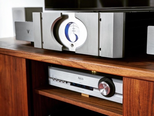
Pass’s XA.5-series styling certainly wasn’t known for its subtlety...
The Valvet counters with a faster, more incisive sound. One of the distinguishing features of the Valvet is the use of a single pair of transistors in the output stage. A number of manufacturers have been taking this approach as of late, including Pass in their XA25 amplifier which takes purism a step further by also eliminating the emitter degeneration resistors. The argument for such a simple topology is that no two transistors behave identically, and thus paralleling them causes some loss of fidelity as you can never get all of them at an identical ideal operating point and things kind of “average out.” The XA30.5 uses 10 pairs of MOSFETs per channel, and it’s only when you listen to the Valvet that you realize the Pass might have a few extra dancers in the troupe who aren’t quite as perfectly in lockstep with the music. The Valvet paints with a finer-tipped brush that can trace all the contours and curves of a musical line with great agility; the Pass doesn’t lack for resolution, but feels a tad slower and mushier, like a brush that has a bit of fuzz around it. This is particularly apparent in the upper frequencies where the Valvet has noticeably more sparkle and precision.
Tonally, both strike me as not deviating very far from neutral, but the Valvet has a subtle bit of upper midrange highlighting that methinks is in part due to its silver internal wiring. Silver tends to have a shinier sound to it, and when balanced well in a system it can really bring the details of a performance alive; but if not properly balanced, it risks sounding lean and forward. With the Valvet, the silver character is applied very judiciously, but I did find I needed to use more relaxed interconnects and speaker wires (e.g. Audience) to get the right overall tonality and perspective. The payoff is in the upper frequencies, where the Valvet makes the Pass sound a bit thick and cloudy by comparison. With a suitable source and preamp (the Gryphon Essence preamp was transformative in this respective), the tinkle of triangles and sheen of violins are presented with effortlessly clarity.

For reference, that’s a bookshelf speaker (Role Kayak) with 4″ woofers.
In terms of Class A qualities, both have wonderfully colorful midranges and a fair helping of liquidity and naturalness, but the Pass wears these quality more on its sleeve by sounding downright lush at times. It also maintains this warmth at higher volume levels where the Valvet can start to get a bit brighter and more strained, perhaps indicating where it’s leaving its Class A bias range. Where both excel is in conveying the lyricism of a tune or the palpability of an instrument or voice owing to their resolving, tonally complete midrange presentations. Both have a singing character that sounds and feels so organic and unencumbered vs. a typical Class AB amp. The Valvet does it with a slightly sharper focus on the lines around instruments and a bit more sparkle and dynamic alacrity; the Pass does it with a big, easy smoothness and weighty low end. Though the Valvet has no problem driving my full-range Audiovector speakers to satisfying volume levels, the Pass feels like it’ll be a bit more effortless and stable into a wider variety of speakers given its beefier output stage.
Going out on a limb: based on Gary Beard’s insightful remarks in Positive Feedback, methinks the Valvet might have more in common with the sound of the newer XA30.8. Gary’s observations of the XA30.5 align very closely with mine, and he describes the 30.8 as being more precise and incisive vs. the 30.5, similar to how I hear the Valvet vs. the 30.5. I would certainly expect the newer Pass to have more grunt than the Valvet given its even more massive power supply, but the Valet might capture some of the delicate qualities of the Pass XA25 as well. Both of those amps would make a really interesting comparison to the Valvet.
Closing Thoughts 🤔
Nit-picking power ratings aside, the Valvet A4 and Pass XA30.5 are both fantastically musical amplifiers that deliver plenty of the famed Class A magic with verve and character. It’s no coincidence that after the Valvet landed in my system, the next two amplifiers I’ve sought out - the Pass and the Gryphon Essence - are also Class A. This isn’t to say I’ll never go back to Class AB (and I’m actually expecting a Class D amplifier soon 😱), but after years of swearing I’d only seek out more practical amps that weren’t so ridiculously big and hot, the Class A bug has bitten me pretty hard. If tonal purity and musical nuance are top priorities for you, amps like the Valvet and Pass Labs deserve a spot on your audition list.
1 note
·
View note
Text
Driving a 16×2 LCD with Voltage Modulation
The basic 16×2 LCD is an extremely popular component that we’ve seen used in more projects than we could possibly count. Part of that is because modern microcontrollers make it so easy to work with; if you’ve got an I2C variant of the display, it only takes four wires to drive it. That puts printing a line of text on one of these LCDs a step or two above blinking an LED on a digital pin on the hierarchy of beginner’s electronics projects.
What’s that? Even four wires is too many? In that case, you might be interested in this hack from [Vinod] which shows how you can drive the classic 16×2 with data and power on the same pair of wires. You’ll still need a microcontroller “backpack” for the LCD to interpret the modulated voltage, but if you’ve got an application for a simple remote display, this is definitely worth checking out.
The basic idea is to “blink” the 5 V line so quick that a capacitor on the LCD side can float the electronics over the dips in voltage. As long as one of the pins of the microcontroller is connected to the 5 V line before the capacitor, it will be able to pick up when the line goes low. With a high enough data rate and a large enough capacitor as a buffer, you’re well on the way to encoding your data to be displayed.
For the transmitting side, [Vinod] is using a Python script on his computer that’s sending out the text for the LCD over a standard USB to UART converter. That’s fed into a small circuit put together on a scrap of perfboard that triggers a MOSFET off of the UART TX line.
We actually covered the theory behind this technique years ago, but it’s always interesting to see somebody put together a real-world example. There might not be too many practical uses for this trick in the era of dirt-cheap microcontrollers bristling with I/O, but it might make a fun gag at your hackerspace.
youtube
Driving a 16×2 LCD with Voltage Modulation was originally published on PlanetArduino
1 note
·
View note
Text
Mobile Accessories
Dual USB Fast Charger & How it Works
So, After so much of research and looking at the market trend we have launched 2.6 Amp Dual USB fast charger model number of the charger is CH-01, and also we are providing the free high speed data cable which also supports the data synchronisation it is 4 core data cable.
Here are Some Key USP of our DUAL USB charger.
Charge Two Devices Simultaneously
Over Current Protection.
Over Charging Protection.
Over Power Protection.
Over Voltage Protection.
Short Circuit Protection.
Temperature Protection.
How Charger Works ??
A Charger, is a sort of force supply called Switched Mode Power Supply. It gives a Constant Voltage (CV) and a Constant Current (CC) to the Battery, furnishing it with the energy expected to charge it.
For the most part, the Voltage is 5V DC, and the Current is 0.5 An or 1 A.
The manner in which it works is, it takes the 220/110 V AC from the Wall Socket, Rectifies it and Converts it into DC Voltage, Filters it, and Passes it through a High Frequency (> than 20Khz ordinarily) Semiconductor switch, by and large a MOSFET or BJT.
This high recurrence current is taken care of into a Transformer, which is impressively more modest than its Line Frequency Counterpart (50/60 Hz). This size is conceivable because of High recurrence Switching. The Voltage on the optional side of the Transformer is then corrected and Filtered and gave as a result. This Voltage is additionally taken care of to a Feedback organisation, which as a rule comprises of an Opto Coupler to give disengagement among essential and optional sides. This input changes the Duty Cycle of the Semiconductor Switch, which helps in directing the Output.
Check out our dual usb charger here https://jordys.in/shop/
1 note
·
View note
Text
Buku Persamaan Ic Dan Transistor Part
Buku Persamaan Ic Dan Transistor Partai
Buku Persamaan Ic Dan Transistor Parts
S8050 Transistor Pinout, Features, Equivalent, Circuit & Datasheet S8050 Transistor Pinout, Features, Equivalent, Circuit & Datasheet Persamaan Transistor S8550. - ELEKTROSEMI Transistor S8050 C1815 S8550 A1015 NPN PNP TO-92 1 pcs di Lapak Electronics Bot | Bukalapak S8050 Transistor Equivalent S8550 D331 Pnp To-92 Transistor - Buy Transistor,Transistor S8550 D331 Pnp Untuk-92,S8050 Transistor Setara Product on Alibaba.com Biyant Rumpoko: NGAKALI PENGANTIAN TR STEERING – QD S8050 Transistor Equivalent S8550 D331 Pnp To-92 Transistor - Buy Transistor,Transistor S8550 D331 Pnp Untuk-92,S8050 Transistor Setara Product on Alibaba.com S8550 Transistor Pinout, Datasheet, Features & Sample Circuit ELECTRONIC CIRCUIT: Transistor Untuk Sistem Regulator Televisi S8050 Buku persamaan ic dan transistor part number - casiniiowa Persamaan 8050 - fasrprotection S8050 Datasheet, Equivalent, Cross Reference Search. Transistor Catalog SS9013 Transistor Pinout, Equivalent, Uses, Features & Applications - Components Info S8050 Transistor Pinout, Features, Equivalent, Circuit & Datasheet Buku persamaan ic dan transistor part number - casiniiowa Daftar Lengkap Persamaan Transistor/Seluruh dan Semua Transistor - zeinzul 200PCS S8050 J3Y 100pcs + S8550 2TY 100pcs 8550 8050 SOT 23 Transistors NPN PNP Silicon Epitaxial Transistor|transistor chip|transistor insulatortransistor switch - AliExpress S8050 Transistor Pinout, Features, Equivalent, Circuit & Datasheet Persamaan Ic Irfz44n - framelight Hot Promo #7be6 - 1000PCS S8050 Transistor TO-92 | Lk.idprices.me Biyant Rumpoko: NGAKALI PENGANTIAN TR STEERING – QD Pengganti Tr C5198 Ampli Toa - castlasopa How To Check Transistor 8050 and 8550 Very EASILY - YouTube 100PCS 2N60 3N60 4N60 5N60 6N60 7N60 8N60 9N60 10N60 TO220 NMOS 600V MADE IN CHINA| | - AliExpress Buku Persamaan Ic Dan Transistor Biasing - athomelasopa Jual Produk Transistor S8050 Murah dan Terlengkap November 2020 | Bukalapak Persamaan Transistor 2N5401 Lengkap dengan Fungsinya - JandelaTV Jual S8050 8050 / 8050SS 500mA 40v npn transistor DIP TO-92 - Kota Semarang - parts-shop | Tokopedia Jual Produk Transistor S8050 Murah dan Terlengkap November 2020 | Bukalapak Persamaan Transistor PNP B507 - lasopahomes PNP Silicon Transistor 2SA1980 A1980 TO 92 New and original with best price|transistor mosfet|transistor datatransistor smd - AliExpress B985 Datasheet - 2SB985, PNP Transistor - Sanyo 2N5551 Transistor Pinout, Features, Equivalent & Datasheet S9012 S9013 S9014 A1015 C1815 S8050 S8550 17valuesX10pcs=170pcs Transistor Assorted Kit for DIY|kit kits|kit transistorkit pc - AliExpress Persamaan Transistor 882 - cubalasopa 20PCS BD135 Transistor TO-126 NPN Power Triode Transistor new and original HJXRHGAL | Shopee Philippines Biyant Rumpoko: NGAKALI PENGANTIAN TR STEERING – QD smd transistor s8050, smd transistor s8050 Suppliers and Manufacturers at Alibaba.com 200Pcs/set 10Types x20 NPN PNP Power Transistors Kit With Box BC337/BC547/2N2222/S8050 Tool Part Accessories Kit|Tool Parts| - AliExpress Buku Persamaan Ic Dan Transistor Biasing - basketlasopa 2N3904 / BC547 / PN2222 / 2N4401 NPN Transistor - NTE123AP Tabel Persamaan Transistor D882 low voltage power transistor, low voltage power transistor Suppliers and Manufacturers at Alibaba.com 20PCS D438 2SD438 TO92 Low Power Transistor|transistor power| - AliExpress S8050 Datasheet, Equivalent, Cross Reference Search. Transistor Catalog China C8050 Transistor, China C8050 Transistor Manufacturers and Suppliers on Alibaba.com Persamaan Transistor 2N5401 Lengkap dengan Fungsinya - JandelaTV PNP Silicon Transistor 2SA1980 A1980 TO 92 New and original with best price|transistor mosfet|transistor datatransistor smd - AliExpress S8050 Datasheet, Equivalent, Cross Reference Search. Transistor Catalog a1273 transistor equivalent, a1273 transistor equivalent Suppliers and Manufacturers at Alibaba.com J3Y S8050 SMD NPN transistor Big Discount #dfcc - TC124E 2SC124 C124 TO-92 | Mm.webpush.me Persamaan Trasistor D313 - hatlasopa EBS) Amplifier Transistor S8050 C1815 S8550 A1015 NPN PNP TO-92 10 pcs 3 Pin 50V Komparator Power | Shopee Indonesia 1a transistors, 1a transistors Suppliers and Manufacturers at Alibaba.com C1815 Transistor Details About Pinout, Equivalent, Uses, Features & More - Components Info Persamaan Transistor Wsl 03751 - fasrlib S8550 Transistor Pinout, Datasheet, Features & Sample Circuit S8050 Datasheet, Equivalent, Cross Reference Search. Transistor Catalog Daftar Lengkap Persamaan Transistor/Seluruh dan Semua Transistor - zeinzul 1pcs 100% new and orginal PN2369A NPN switching transistors TO 92 in stock| | - AliExpress Jual mje13003 npn transistor - Kab. Bandung - KME_shop | Tokopedia How To Check Transistor 8050 and 8550 Very EASILY - YouTube persamaan thx203 - SHEMS Persamaan Transisto C945 - marlasopa S8050 Datasheet, Equivalent, Cross Reference Search. Transistor Catalog 2N5551 Transistor Pinout, Features, Equivalent & Datasheet Buku Persamaan Ic Dan Transistor Tester Stripboard Horizontal Boîte de transistors 200PCS BC337 BC327 2N2222 2N2907 2N3904 2N3906 S8050 S8550 A1015 C1815 Maroc - Dsindustrie.com Persamaan Ic Irfz44n - framelight persamaan ic sw2604 - SHEMS original New) Pnp Transistor Tip122 Tip127 - Buy Transistor Tip122 Tip127,Pnp Transistor Product on Alibaba.com S8050 Datasheet, Equivalent, Cross Reference Search. Transistor Catalog C945 Library for Proteus - The Engineering Projects lecture22-understanding%20bjt%20circuits | Bipolar Junction Transistor | Electronic Engineering Jual Produk Sejenis Jual 10x S9012 Transistor PNP NPN FCS 9012 9013 8050 8550 C9013 C8050C8550 - Juragan elektro Torehan Pena Musafir: Coretan Pengganti Transistorku Prod Export All | Business Persamaan Tr Fet K2961 KSP92 pnp transistor complementary npn, replacement, pinout, pin configuration, substitute, marking KSP 92, equivalent smd, datasheet S8050 Datasheet, Equivalent, Cross Reference Search. Transistor Catalog Transistor K1305 | china transistor st13005 china st13005 bta137 600d, 5 x mje13005 13005 quot kec quot npn transistor 4a 400v ebay, transistor k13a60 eletr 244 nica castro, transistor k13a60 eletr 244 Transistor C9013 | Shopee Indonesia Buku Persamaan Ic Dan Transistor Tester Stripboard Horizontal Persamaan Transistor D965 - sagefasr Jual 25tts12 asli persamaan tyn1225 scr maks 25a 1200v - Jakarta Barat - PCM ELEKTRONIK JAKARTA | Tokopedia Transistor / MOSFET Tutorial: basics how to use - YouTube Persamaan Transistor S8550. - ELEKTROSEMI persamaan thx203 - SHEMS Jual Produk Sejenis Jual 10x S9012 Transistor PNP NPN FCS 9012 9013 8050 8550 C9013 C8050C8550 - Juragan elektro B985 Datasheet - 2SB985, PNP Transistor - Sanyo Boîte de transistors 200PCS BC337 BC327 2N2222 2N2907 2N3904 2N3906 S8050 S8550 A1015 C1815 Maroc - Dsindustrie.com S8050 Datasheet, Equivalent, Cross Reference Search. Transistor Catalog Bridgold 10pcs E13009-2 E13009 13009 High Voltage Fast-Switching NPN Power Transistor TO-220: Amazon.com: Industrial & Scientific Transistor C945 Datasheet Pdf Persamaan Tr K2961 - lasopabuddy Jual 29M33A TO-220 - Kota Tangerang Selatan - Jabar Elektronika | Tokopedia TR BC560 BC 560 Transistor | Shopee Indonesia 8772 Transistor Suppliers, all Quality 8772 Transistor Suppliers on Alibaba.com lecture22-understanding%20bjt%20circuits | Bipolar Junction Transistor | Electronic Engineering
TOKO ONLINE BUKU ELEKTRONIKA. Setiap Pembelian 2 Buku Elektronika, Anda mendapatkan GRATISSS dvd Skema TV dan Software Persamaan IC. Persamaan IC, transistor, mosfet. Transistor as a switch.pdf. Download Buku Persamaan Transistor Dan Ic, Buku Persamaan Transistor Download, Buku Persamaan Ic Dan Transistor. Persamaan komponen; data ic. TOKO ONLINE BUKU ELEKTRONIKA DAN ALAT. (integrated circuits), tdv (transistor, FET). Mengenalnya masih berupa “Buku Persamaan Semikonduktor ( IC, transistor. Advertisement Mencari Persamaan Transistor - Sudah lama sekali saya tidak terlibat dengan perhitungan transistor, terakhir kayaknya dulu waktu masih sekolah suka merakit amplifier.
Jumat, 25 Januari 2013. PERSAMAAN TRANSISTOR. Menambah Game Pada HP China non-Java Bagi para pengguna HP buatan China mungkin kita merasa bosan dengan aplikasi dan game yang jumla. You have not yet voted on this site! Buku persamaan ic download buku persamaan buku persamaan ic ebook ic dan transistor pdf.
Buku Persamaan Ic Dan Transistor Theory. Watch thuy nga paris by night 113 mung tuoi me full hd part 2 MP4 video for free, Video HD: thuy nga paris by night 113 mung tuoi me full hd part 2, id: mU0bfTIq2LA. Watch thuy nga 113 paris by night 114 chinh thuc full dvd MP4 video for free, Video HD: thuy nga 113 paris by night 114 chinh thuc full. Buku Persamaan Ic Dan Transistor Amplifier Circuit Average ratng: 9,8/10 6767votes Rangkaian pre amp mic 2 transistor. IC (Integrated Circuit). Dan perbedaan produk rekayasa elektronik praktis dan otomatis,persamaan dan perbedaan produk.
Buku Persamaan Ic Dan Transistor Partai
Wirkam blogthis is a running message display circuit wherein the letters formed by the led arrangement light up. Perbedaan mesin cuci 1 dan 2 tabung dan cara. TRANSISTOR TESTER Circuit The 555 operates at 2Hz. Output pin 3 drives the circuit with a positive then zero voltage. The other end of the circuit is connected to a voltage divider with the mid-point at approx 4.5v. This allows the red and green LEDs to alternately flash when no transistor is connected to the tester.
If a good transistor is connected, it will produce a short across the LED pair when the voltage is in one direction and only one LED will flash. If the transistor is open, both LED’s will flash and if the transistor is shorted, neither LED will flash. Transistor Tester Transistor Tester To buy a kit: There is a certain amount of skill required to design a circuit but a lot of skill to simplify it. There are lots of transistor tester circuits on the web and they all do the one thing - identify a PNP or NPN transistor. Some provide the gain and even the maximum operating voltage but in most cases we only want to know the c, b, e pin-out and if the transistor is NPN or PNP. That's what this tester does. It lets you know the pin identification.
Gta vice city cheats codes for computer free download. Now just Read and up to 60 gta vice city Codes insert these below are only works on your pc or laptop. Pick up a pen, marker or pencil along with pages or copy/register in your hand and write it. Free download gta vice city. Get free Grand theft auto vice city pc game cheats for free. Gta vice city cheats are used to make the missions easy and hence its easy to play game. Grand Theft Auto Vice City PC Game Cheats - Download PC Games For Free. For Grand Theft Auto: Vice City on the PC, GameFAQs has 125 cheat codes and secrets. Buy Assets for Free (PC-only). Kingdom Hearts III Guide Red Dead. GTA Vice City cheats PSP helicopter code is New Game in the Series of Popular Computer & Xbox 360 GTA games. The Release Gta Vice City Cheats Helicopter Pc, Helicopters have been valuable Means of Transportation in Game.
Buku Persamaan Ic Dan Transistor Parts

And, amazingly, it only uses a few components. The secret is the transformer.

It's a flyback transformer that produces a high voltage when the transistor switches off and this voltage is used to illuminate a single LED for the PNP transistor and 2 LEDs for the NPN transistor. Sony vegas pro 10 free download torrent. The two LEDs in series are used to produce a voltage greater than 1.7v + 2.3v = 4v so the 4v can be used to illuminate a white LED placed on the 'Test LED' pins. The project uses a single 1.5v cell and this voltage is below the 1.7v needed to illuminate a red LED so no power switch is required.
There is only one trick to get the circuit working. The phase of the transformer winding must be correct to get the circuit to oscillate. Both windings are 40 turns so it does not matter which winding is used for the primary or which is used for the feedback. The feedback winding could be a small as 10 turns but 20 turns or more is guaranteed to get the circuit to work. But if the feedback winding is not connected around the correct way, the circuit will not work. There is no danger of excess current when the feedback winding is greater than required, it just produces a very brightly illuminated LED. You can learn a lot about the effect of one winding of a transformer on another in this air-cored example by slowly bringing the two windings together to see the circuit start to work.
When the flux density is very low, an air cored transformer is just as good as iron or ferrite cored and when the current is turned off very quickly in one of the coils, it produces a collapsing flux that cuts the turns of all the coils and produces a high voltage in them of the opposite polarity. This is the voltage that illuminates the LED because the supply is only 1.5v and it is not capable of doing this. Thus we can prove it is the transformer that increases the voltage. In fact the voltage is high enough to illuminates two LEDs in series.
0 notes
Text
RunOffGroove 22/7 Build
Here is another 22/7 build. It’s a Big Muff variation. This unique circuit replaces the transistor stages of the classic Big Muff with CMOS inverters. It’s a unique flavor of Muff. CMOS inverters have their own unique flavor of distortion and have been used in many classic pedals like: Craig Anderton’s Tube Sound Fuzz, Way Huge Red Llama, Blackstone Appliances MOSFet Overdrive.
The 22/7 was created by the unstoppable genius over at RunOffGroove.com. They have a lot great stompbox designs and great information, be sure to check out their site.
Build your own
I designed the PCB and created a project over at OSH Park. Check out my build Docs to read more about the circuit and learn how to make your own! The PCB is designed with the the pots, switch and LED mounted to the board for ease of assembly.
Build post here for parts and PCB: http://www.super-freq.com/22-7-on-osh-park/
Build Process
For this build I used a powder coated enclosure and milled the labels and logo through the powder coating with a desktop mill. This process works for me and I can do everything myself at home with no chemicals and little set up and clean up. I want to give UV printing a try in the future, I’ve seen a lot great results! I’ll be writing a blog post about it in the future.
What’s it sound like?
Sounds a lot like a Big Muff but with its own character. The hex inverters have their own flavor but the strong clipping inherent in the Big Muff architecture dominates the sound giving it the characteristic Big Muff sound. I suspect you hear hex inverters as the last inverter is overdriven by the rest of the circuit. I’d say you get the classic Big Muff clipping sound but you don’t get the over saturated sound you can get with a Big Muff when the input is too hot or the sustain high.
The 22/7 has a switch that changes the range of tone control through three different ranges. This changes the range and sweep of the tone control to match other big muff models. There is a Classic option which is described as an average tone model of classic Big Muff models. A Flat option which creates a flat tone response removing the mid scoop of the classic mode, this is a well known mod. Last is the Scoop mode which creates a deeper mid scoop, I compare this to the sound of the original Way Huge Swollen Pickle.
I like the last mode on its own, but the flat mode sounds better with the band. writing this in 2021 I’m spending all of my time playing at home so all the modes sound great!
This has been my favorite Big Muff of late! It’s got a good sound and the tone control hits a very usable range.
youtube
RunOffGroove 22/7 Build was originally published on Super-Freq
0 notes