#diode small signal resistance
Explore tagged Tumblr posts
Visit Tumblr Blog
Explore Tumblr blogs with no restrictions, modern design and the best experience.
Last Seen Tumblr Blogs


Fun Fact
Tumblr’s reach among the 26-to-35-year-olds in the US is 11%.
Text
https://www.futureelectronics.com/p/semiconductors--discretes--diodes--small-signal-diodes/sstpad5-lf-calogic-1036092
Application of signal diode, switching circuits, types of signal diode
SSTPAD5 Series 1.5 V 10 mA Surface Mount Pico Amp Diode - SOT-23
#Calogic#SSTPAD5-LF#Diodes#Small Signal Diodes#application#switching circuits#diode small signal resistance#low voltage signals#diode voltage drop#High speed small signal diodes#PN junction diode#Schottky diode
1 note
·
View note
Text
Understanding Circuit Board Electronic Components: A Comprehensive Guide
In today's digital world, electronic devices have become an essential part of our daily lives. But what makes these devices tick? At the heart of every electronic device lies a circuit board—a masterpiece of tiny electronic components working together to perform complex tasks. In this article, we’ll dive deep into the fascinating world of circuit board electronic components, exploring each element’s role and how they contribute to the overall functionality of the device.
What is a Circuit Board?
A circuit board, often referred to as a PCB (Printed Circuit Board), is a flat board used to mechanically support and electrically connect various electronic components. These components work in unison to perform a specific task. Think of the circuit board as the skeleton and nervous system of an electronic device—it holds everything together and allows communication between parts.
Types of Circuit Boards
Single-sided PCB: Has one layer of conducting material.
Double-sided PCB: Contains two layers for components and connections.
Multi-layer PCB: Complex boards with multiple layers for advanced applications.
The Role of Electronic Components on a Circuit Board
Every electronic device you interact with is powered by a carefully designed circuit board filled with various components. These components might be tiny, but each one has a critical role in the operation of the device. Here's a breakdown of the most important electronic components you’ll find on a typical circuit board.
1. Resistors
Resistors are fundamental components that control the flow of electrical current. They resist the flow of electrons, hence the name "resistor." Their primary function is to reduce current flow, adjust signal levels, and divide voltages in a circuit. Without resistors, circuits would allow too much current to flow, potentially damaging other components.
Types of Resistors
Fixed resistors: Have a set resistance value.
Variable resistors: Allow adjustment of the resistance.
2. Capacitors
Capacitors store and release electrical energy in a circuit. They are often compared to small rechargeable batteries that quickly charge and discharge. Capacitors help smooth out fluctuations in voltage, filter noise, and store energy for future use.
Common Uses of Capacitors
Energy storage
Signal filtering
Voltage stabilization
3. Inductors
Inductors are components that store energy in a magnetic field when electrical current flows through them. They resist changes in current and are typically used in circuits to filter signals, manage power, and store energy.
Applications of Inductors
Power supplies
Radio frequency circuits
Noise suppression in circuits
4. Diodes
A diode is like a one-way valve for electricity, allowing current to flow in only one direction. They are vital in circuits to prevent reverse currents, which can damage components.
Types of Diodes
Light-emitting diodes (LEDs): Produce light when current flows through.
Zener diodes: Regulate voltage within a circuit.
5. Transistors
The transistor is a versatile component used to amplify or switch electronic signals. In essence, transistors are like tiny switches that turn signals on and off rapidly, making them essential in modern electronics.
Types of Transistors
NPN transistors: Allow current flow when a small voltage is applied to the base.
PNP transistors: Conduct when the base is negatively charged.
How Circuit Board Components Work Together
In a circuit, each component has a specific role, and together they form a cohesive system. For example:
Capacitors and resistors may work together to filter signals or smooth out voltage fluctuations.
Transistors and diodes ensure that signals are amplified or directed properly.
Integrated circuits handle the complex tasks, processing data, and controlling the overall system.
Choosing the Right Components for Your Circuit Board
When designing or repairing a circuit board, choosing the correct components is crucial. Some factors to consider include:
Voltage requirements
Power consumption
Signal type and frequency
Physical size and compatibility
Conclusion
Circuit boards are an integral part of any electronic device. The various components on the board each play a specific role in ensuring the device functions as intended. Understanding these components, from resistors to integrated circuits, is essential for anyone working with electronics, whether you're designing a new system or troubleshooting an existing one.
2 notes
·
View notes
Text
AM-Detection -the not easy way
Sometimes quite simple things can be a real nightmare if you take a closer look. One of those is AM detection. Your worst enemies are distortion and fading (the latter results in the first). The AM-Detector is only one little part in a receiver, exactly that kind of part usually no one thinks about. "It works, so what should be wrong with?" -a lot and sometimes there's more wrong than right.
A good part of that distinctive AM-Sound we all know is because of the Detector, even under the best conditions. If you're listen to shortwave or the broadcast band during the night then you also have to cope with Fading. Shouldn't be that problem, the automatic gain control takes care of that, right? Ehmmm... Yes. Sometimes. Why the sound gets so distorted when the signal goes down? Just because it's very often 'Selective Fading' and not just Fading -and your Detector doesn't like it.
Really good AM-Reception has a lot in common with High-End-Audio: if it shall work well EVERYTHING has to be well. So let's just talk a bit about Detectors...
Basically the Detector just splits the Audio Signal from the received and amplified Signal. Sounds easy and in fact it is -up to some degree. If you want more than this things getting complicated -really complicated. In at least 999 out of 1000 AM-Receivers for the Detector a small circuitry called 'Envelope Detector' is used, it's just a small Diode (Tube or Semiconductor), a few Resistors and small Capacitors. So, from the view of the Development Engineer: just put half a dozen cheap Components together and Bob's your Uncle. To tell the Truth: compared to the expense that thingy works surprisingly well. Because of this it's the 'Gold Standart' for this task since at least the mid 30s. But as good as it is, it absolutely has it's Limitations. Up to about 15...30% Distortion at a 100% Modulation Level is one, the inability to detect a signal with different sidebands (>selective Fading!) properly another.
To overcome these Limitations a thing named 'Synchronous Detector' was developed many Decades ago. This kind of Circuit has many advantages over the Envelope Detector, but to make one the complexity and the component count of those is just hilarious compared to the Envelope Detector. If only the result counts and nothing else: that's the way to go. We'll talking later how this exactly works, but before this you have to know that in a receiver with a Synchronous Detector also an Envelope Detector is needed: just for tuning in. So first we'll have a closer look how we can get the most ideal Envelope Detector.
Basically it's quite simple: want to have low overall Distortion? Feed it with at least 'a few' volts RF at it's input for having a high ratio between the input voltage and the 'forward voltage' of the Diode. Want low Distortion at low modulation levels? Use a Diode with low Impedance and a load Resistor with a value as low as possible. Want low Distortion at high modulation levels? Just make the input Impedance of the following Stage as high as possible for having the highest possible Ratio between the Resistance of the Load Resistor and the input Impedance of the following Stage.

The Receiver i wanted to use (R+S EK07) has an IF output, meant for exactly such things, the IF Level there's about 250mVpp @ 300kHz. So having everything above in mind -and just adding a 700mVpp IF output for the Synchronous Detector and an additional AGC-Circuitry, then we're coming to this:

The EK07 is a fully tube equipped receiver, so i also want to use tubes as far as possible and -like in the EK07- in a way which guarantees 10k's of Service hours. If at one point a Semiconductor may perform muuuch better -ok, so then. First of all i want high performance. So what tubes may perform optimal here?
For the first IF-Amp (IF1) not much is needed, the Gain is only about 3, the output voltage low and besides that it has to be an remote-controlled type. Selectivity isn't needed or desired, so no IF-Can, only a Broad-Band setup. Nearly every IF-Tube with a Transconductance of at least about 3000mhos (3mA/V) would do that job. To have better performance i took the EF805s, which is a Special Quality Version of the EF85 -or 6BY7.
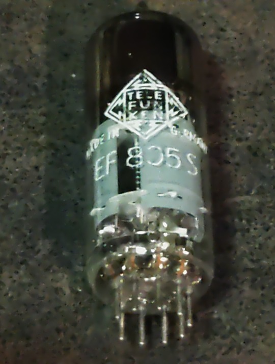
Transconductance is about twice what's needed, so we'll have Gain to spare, anyway, it's getting controlled with the AGC so it will work with less current which adds greatly to the service life. So no problems here.
For the second IF-Amp (IF2), things aren't exactly that easy. First: the output for the Synchronous Detector is placed between both Amps and has to deliver a constant voltage, so for the 2nd IF we need an Amplifier with an fixed Gain. A STABLE fixed Gain over long time periods. Further we want to have a relatively high and undistorted output voltage which calls for quite a bit of gain. Wait: there was also that thing with the low-value Load Resistor in the detector itself -so we also need a quite reasonable amount of output power from this stage. In Addition we want to have a stable gain for a time as long as possible. A IF-Tube like the EF805s could also handle this, but then we have to 'beat the crap' out of this thing. Not a good start for a long and stable service life, also not with Special Quality Tubes.
Because of all that my choice was a kinda 'special'-Special-Quality type: the E81L.

The datasheet calls this a 'Long range, Special Quality Tube for the use in Telephone Equipment'. Telephone Equipment? Like an answering machine?? Nope, by far not. Back in these days telephone companies needed to have Amplifiers for pushing the calls through loooong cables for long range service. But: this was all multiplex service, so they pushed dozens and dozens of calls simultaneously through one pair of wires or a Coax. The same way like for cable TV. THIS was these bulbs were meant for. For this task every company employed tens of thousands of such tubes 24/7/365. If a single one failed -most likely somewhere in nowhere of course- they had a problem. So they absolutely had to last.
These little bulbs are designed for about 4.5W plate dissipation at 20mA, the Transconductance is 11000mhos (11mA/V)-so it's about twice an usual IF Tube in every respect. So that's exactly what's needed here: a tube especially designed to last, quite powerful, so we can drive it with comfortable low settings, enhancing service life and stability much further.
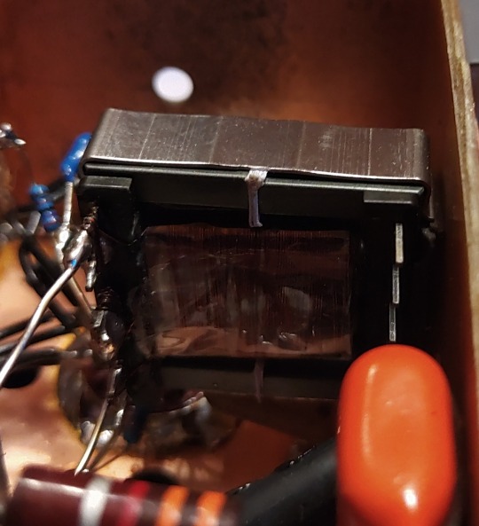
Because we need some amount of power the usual Broad-Band Amplifier arrangement (still: selectivity is not wanted or desired) with just a plate Resistor isn't good here, a suitable inductor works way better here. This has the further advantage that we can build it with a Tab like an Autotransformer -we don't need that much voltage it could deliver with that inductor by far, so this adds further to a good SNR and lower output Impedance. 300kHz trough a transformer? Yep, no problem. Just use the right core. Here it's not a laminated iron core but a ferrite one instead. Cause it's a single-A Amplifier of course we must add an air-gap, preventing saturation.
In a penthode stage the gain depends nearly exclusively on the Transconductance of the tube used, have to much just cut it down. The E81L has a quite high transconductance, about 3 times more than needed -and in the same order than big output tubes like the 6550, EL34 or 6CA7. For cutting that down to the desired level just put a Resistor or Pot in series to the bypass cap of the cathode Resistor. This acts as an series feedback so it also enhances linearity and long time stability greatly. Yap, i thought quite a while about which tube i should use here.
So after all Amplification is done now, we need a Diode for the Envelope Detector. Back in the Octal-Days this was the 6H6 / EB34, later in the Miniature-Days the 6AL5 / EAA91, both with two separate diodes in one bottle (or Can for the 6H6). These were not A DIODE, these were THE DIODE, so there's not much to choose from. Both are kinda close to each other, but are these ideal for what we want? They both can handle a reverse voltage of several hundreds of volts, so waaaay more than we need here. Both having a Plate Resistance of 600-something Ohms per System which is quite low -could be lower, even with both Systems in parallel. Of course these would be work well, no doubt about. But still.... Hey, this should be High-end so we're whining here at a very high level!
Basically we can use EVERY TUBE as a diode: just take the control grid as Anode, the Cathode as what it is and everything else as Shielding. We don't need hundreds of Volts reverse Voltage, nor high current, so also no big Cathode. We only want to have an internal Resistance as low as possible, so a close spacing between the Grid and the Cathode. This calls for a small Tube with a high Gm (or Transconductance) -like the 6AK5 / EF95. Can it handle the reverse voltage we need? Datasheet says 50V, so at least twice of what's needed. So just take one, put some current trough and take the voltage drop. Result: 210 ohms -way less than that what one of the double-diodes would provide, even with both Systems in parallel. Fits very well!

This is the soviet-military version of the 6AK5W / E95F. Special Quality. See these 'trenches' in the bulb? And the microscopic rivets holding the Plate together? The Soviets literally ruggedized the heck out of this tube! Why? Just because they used it widely in their Fighter Planes, ICBM's, Tanks and so on. Doubts about the soviet built quality? Hey, they wanted to win WWIII with them -so: nope. If you ever saw a ruggedized tube: this it is.
After the Detector itself is done, we come to last part of our little contraption: the buffer Amplifier. At the output of the Detector we have the AF as well with the overlayed AGC-Voltage and we want to have an input Impedance as high as possible for the Buffer Amp. Voltage Gain isn't needed -we have plenty of both from the Detector- so we just can use a Cathode Follower for the buffer. Ideally the Buffer should handle both voltages simultaneously, but then the output will be negative with respect to Ground. How to....? Simple: just put that thing between a positive and a negative supply rail. Then the output can swing freely between every positive or negative Potential as desired. Further: we don't need a Grid Resistor! The Grid just follows any voltage swing of the Detector, this also adds to a high input Impedance.
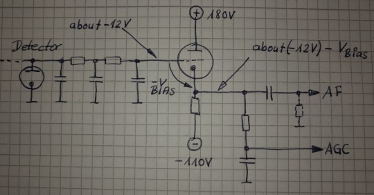
This Circuit will provide us a very high input Impedance, but this is High-End! So: what tube will be the best for? Because of the lack of any Grid Resistor the input Impedance depends now largely on the contact potential of the grid. So we want a tube with low contact potential which calls for a tube with a low Transconductance. Further we want a tube which needs only a low bias voltage for it's Grid, 'cause we'll loose any bias-volt in our AGC-Output voltage. This calls for a tube with an high Gain. Low contact potential and low Transconductance? High Gain?? That's the 12AX7 / ECC83! Ok, it's of course a double Triode, but we still can use the second system for something else -like for the Line-Output Amp. In that Stage there's not much needed so it also will perform well enough there -we're still talking about AM!
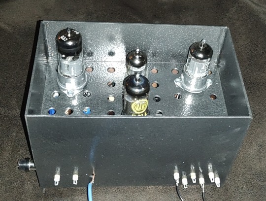
So let's put everything neatly together, adding adequate shielding and so on -and we get this:
So now it's time to have a closer look we did everything right. Just put a 300kHz-Carrier in, 100% modulated with a triangle-signal. We should get a perfect Triangle at the AF-Output -if physics are with us. Due to the Triangle Signal any Distortion can easily be spotted on the Scope.
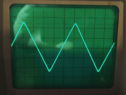
Looks promising! But somehow... Is the beam defocused? Let's take a very close look:

No, it's not. Those are just the very small remnants of the Carrier, so we actually have a look how the Detector works on a nearly 'microscopic' Level. I could take a measurement how much distortion we have left, but the Flanks of the Triangle are perfectly straight, so the Distortion will be really small -like 1% or so worst case. At least for the moment it's not worth the Effort. Compared to the usual 15...30% Distortion at a 100%-Modulation level this works really well, there's no doubt about.
So finally: we wanted to have a Envelope-Detector as good as possible and here we are. Ok, tbh it's better than needed, cause finally the REAL Detector will be a synchronous one. So why i took this that far? Easy: because of mental peace. Now i never have to think about if that part of the whole final thing could work better. As i said before: it's High-End.
Will update you if the next module is ready. But i fear this here was just the more easy part of the whole thing. From now on things may get a bit more tricky...
3 notes
·
View notes
Text
The Amazing World of Sensor Detectors are devices that detect and respond

What are Detectors? Detectors are devices that detect and respond to some type of input from the physical environment. The specific input could be light, heat, motion, moisture, pressure, or any other physical phenomenon that can be measured. By converting the input to an electronic signal, detectors enable monitoring and automating real-world processes.
Types of Common Detectors There are many different types of detectors based on the specific input they are designed to detect. Here are some of the most common detectors used today:
Light Detectors Light detectors detect illumination levels and are used commonly in automatic lighting controls, camera auto-focus systems, and digital clocks that glow in the dark. Common light detectors include photo resistors, photo diodes, and photo transistors that change their electrical properties depending on the amount of light striking their active surface.
Temperature Sensor Temperature detectors measure ambient or surface temperature and often output an analog voltage that varies with temperature. Sensor Thermistors and thermocouples are widely used temperature detectors. Thermocouples generate a small voltage proportional to the temperature difference between two junctions of dissimilar metals. Thermistors change their electrical resistance with temperature in a known manner. Temperature detectors find applications in thermostats, medical equipment, heating/cooling systems and more.
Motion Detectors Motion detectors detect movement of objects and people. Passive infrared (PIR) motion detectors are commonly seen in outdoor lighting and security systems. Ultrasonic motion detectors detect motion by sensing changes in ultrasonic patterns. Optical mouse detectors also fall into this category as they sense motion and movement. Industrial robots often use motion detectors to detect position and speed.
Pressure Detectors Pressure detectors measure the force per unit area applied on their surface. Strain gauge pressure detectors change their electrical resistance with the amount of applied pressure. They are used to measure everything from tire pressure to blood pressure. Capacitive pressure detectors use capacitance changes to sense pressure. Piezoresistive pressure detectors alter their electrical resistance when strained under pressure.
Proximity Detectors Proximity detectors indicate if an object is near or within a given distance range without physically touching it. Common proximity detector technologies include ultrasonic, infrared, inductive loops, and laser optical. They find widespread use in industrial machine automation, assembly lines, and object detection applications.
Advancing Micro-Detector Technology As microchip fabrication technology advances, detectors are becoming smaller, cheaper, and more powerful. Microelectromechanical systems (MEMS) allow detector features to be integrated directly onto silicon chips alongside digital circuits. This opens up many new possibilities for pervasive sensing across diverse industries.
Tiny environmental detectors based on MEMS accelerometers and gyroscopes enable motion-activated user interfaces and electronic stability control in vehicles. MEMS pressure detectors monitor engine performance and structural stress. MEMS microphone arrays support speech-enabled user interfaces and noise cancellation. Miniature biodetectors based on chemical detectors, bio-implants, and DNA/RNA identification promise to revolutionize personal healthcare.
The Internet of Things (IoT) is accelerating detector innovations further by connecting everyday objects and environments to the internet. Embedded with detectors, things like home appliances, industrial equipment, vehicles, medical devices, infrastructure, and consumer goods continuously monitor their own status and environmental conditions. Wireless MEMS pressure and temperature loggers track shipments. Smart lighting uses embedded motion and light detectors for enhanced efficiency and user experiences. Detectors will further shrink and proliferate in the coming years towards realizing a fully sensed world.
Future Directions in Sensor Technologay By combining multiple detector capabilities on single chips, we can sense increasingly complex phenomena. Multidetectory systems merge data from MEMS accelerometers, magnetometers, gyroscopes, and microphones to accurately track motion, orientation, and location in three-dimensional spaces. Advanced data processing allows taking inputs from diverse detector arrays to identify odors, flavors, textures, and properties beyond the scope of individual detectors.
Biodetectors and chemical detectors hold much promise in areas like biomedical testing, environmental monitoring, and healthcare. Rapid DNA sequencing using nanodetectors may enable non-invasive, real-time medical diagnostic tests. Taste detectors that mimic human physiology could revolutionize food quality assessment. Small, low power gas detectors networked throughout smart buildings may help detect hazardous leaks instantly. Continued research is sure to yield new types of detectors we have not even imagined yet.
Sensor play a huge role in our world by enabling the interaction between electronics and the real world. Constant advancements in microfabrication and computing power are expanding sensing capabilities to unprecedented levels with each new generation of technology. In the future, sensing will become even more pervasive, intelligent and seamlessly integrated into our daily lives for enhanced convenience, safety, sustainability and scientific discovery. Get More Insights On, Sensor About Author: Ravina Pandya, Content Writer, has a strong foothold in the market research industry. She specializes in writing well-researched articles from different industries, including food and beverages, information and technology, healthcare, chemical and materials, etc. (https://www.linkedin.com/in/ravina-pandya-1a3984191)
0 notes
Text
The Emergence and Multiplicity of LED Light Bars: Lighting Up the Future
The Emergence and Multiplicity of LED Light Bars: Lighting Up the Future
In the volatile lighting technology, LED light bars have risen as a force to reckon with in terms of redefining illumination standards. Their small size, high luminance and energy efficiency distinguish LED light bars that are widespread in several industries and applications as well, thus revolutionizing our way of lighting up things around us. The article starts by exploring the growth of LED light bars, their peculiar characteristics, common uses as well as advantages associated with them.Get more news about LED light bars,you can vist our website!
Introduction
LED light bars embody the height of modern lighting ingenuity combined with practicality. Such products make use of light-emitting diodes (LEDs), providing excellent lightning effects while using considerably less power than traditionally used sources. They have found their place in almost every industry including automotive, industrial among other recreational activities due to their flexibility and toughness.
Unique Features of LED Light Bars
High Luminous Intensity and Long Life Span: One main characteristic of these devices is that they produce intense beam for large spaces illumination purposes. Moreover, they can last for more than 50 000 hours which assures stable performance over years ahead.
Energy Saving: For example if we consider an incandescent bulb or halogen bulb technology; LEDs are consuming far less power which makes it an economically efficient option that is also friendly to nature.
Durability and Resistance to Weather Conditions: Made from tough materials, these types of lights are constructed so that they could withstand harsh weather conditions making them perfect for outdoor employment.
Customization: In addition to being available in different lengths as well as colors plus beam patterns LED light bars also come along with great customization options compared to others that will go according to various needs.
Applications of LED Light Bars
Automotive Sector: When it comes to off-road automobiles this type of product is crucial since it provides excellent visibility under low-light situations; additionally they act like headlights or fog lights, and can be used as emergency vehicle lighting too.
Industrial and Construction: To serve the purpose of heavy duty tasks that require a lot of visibility LED light bars are extensively used in factories, warehouses and construction sites.
Outdoor Recreation: This type of product is preferred when it comes to outdoor entertainment by campers, hikers, and boaters due to its size that is small brightness, as well as resistance to shocks.
Emergency Services: Emergency services like police, fire departments or ambulance services include them in their vehicles for immediate signaling of accidents.
Home and Garden: They are becoming popular for home use including accenting lights under counters lighting among others even security purposes these days
Benefits of LED Light Bars
Cost Savings: The cost savings that come with these devices are low power consumption rates as well as their long life span.
Environmentally Friendly: It is a green choice since it has reduced energy usage and no harmful emissions made up by LED light bars
Improved Safety: In such instances as motor cars or emergency services led light bars increase safety by improving visibility hence accidents can be minimized.
Versatile Design: Due to their small size and numerous variations available led light bars can fulfill different needs in some fields.
Conclusion
The Rise of the LED Light Bars – A Milestone. Their characteristic high luminance together with efficiency, toughness plus versatility have made them indispensable tools across industries. As technology continues advancing there will be more innovative strides in the development of LED light bars ultimately leading us into future.
0 notes
Text
LED auto lights refer to the use of LED technology for both internal and external lighting. External lighting equipment involves thermal limits and EMC issues, as well as many complex standards for unloading load tests. LED auto lights can be widely used to create an in-car environment with a service life of 50,000 hours. The structure of LED is sturdy and not easily affected by vibration, and the light output brightness will not drop significantly during use. LED car lights are suitable for various lighting applications in automotive electronics, including headlights (high beam and low beam), fog lights, taillights, brake lights, turn signals, daytime running lights, pedal lights, instrument lights, license plate lights, door lights, interior lights, width lights, navigation, entertainment systems, backlights and indicator lights.
Advantages:
1. Energy saving: The light-emitting diode directly converts electrical energy into light energy, and the power consumption is only 1/10 of that of ordinary car bulbs, which can better save fuel consumption and protect the car circuit from being burned out by excessive load current.
2. Environmental protection: There is no ultraviolet and infrared in the spectrum, low heat, no radiation, low glare, and the waste can be recycled, no pollution, no mercury, safe to touch, and it is a typical green lighting LED source.
3. Long life: There is no loose part in the lamp body, and there are no shortcomings such as easy burning of filament light, heat deposition, and light decay. Under the appropriate current and voltage, the service life can reach 80,000-100,000 hours, which is more than 10 times longer than the life of traditional light sources. (It has the characteristics of one-time replacement and lifelong use)
4. High brightness and high temperature resistance. (Electric energy is directly converted into light energy, low heat, and can be touched by hand, safe and secure)
5. Small size. The designer can change the lamp mode at will to diversify the car shape. The reason why automobile manufacturers favor LED is entirely determined by the advantages of LED itself.
6. Good stability and strong anti-seismic performance of LED: resin encapsulation, not easy to break, easy to store and transport.
7. High luminous purity, clear and bright colors, no need for lampshade filtering, and light wave error within 10 nanometers.
8. Fast response speed, no hot start time required, can emit light within microseconds, while traditional glass bulbs have a 0.3 second delay, which can prevent rear-end collisions and ensure driving safety.
Disadvantages:
1: LED headlights are more expensive than ordinary headlights. (With the continuous popularization of LED applications, prices will be further reduced)
2: It is difficult to popularize car headlights, and the heat dissipation is not good. If the heat dissipation is not properly handled, it is easy to light decay, which affects the service life of the headlights.
3: There are no industry standards issued, and the product quality is uneven. The price of the same product produced with different LEDs varies by 1-2 times. Fortunately, a small number of companies implement standards higher than the general industry standards, so product quality control is better than most companies, such as SNGL brand companies, etc.
1 note
·
View note
Text
Analysis of the advantages and disadvantages of common LED display splicing
LED display splicing technology occupies an important position in modern display technology. With the continuous growth of market demand, various splicing screen technologies have also been continuously developed, and each technology has its own unique advantages and disadvantages. This article will analyze several common splicing screen technologies in detail, including LED display splicing, projection DLP splicing and plasma PDP splicing.

LED display splicing
LED display splicing is to control the display mode of semiconductor light-emitting diodes, and display text, pictures, animations and video content by turning on and off red, blue, white and green LED lights. LED display splicing has the following characteristics:
Advantages
Long life: LED lamps usually have a long service life and can run continuously for tens of thousands of hours. Spherical display: LED display screens can be made into spherical shapes, which are suitable for a variety of special scenes and creative displays. Here are 5 common creative LED screens. Durable: LED display screens have high durability and can resist the influence of the external environment, making them suitable for outdoor applications. Bigger, thinner and more stable: LED displays can be made very large while maintaining a thin design and stable performance.

Disadvantages
Obvious pixels: When viewed at close range, the pixels of LED displays may be more obvious, affecting the viewing experience. Dot spacing limit: The finest LED dot spacing in the industry is currently 1mm, which limits the miniaturization and fineness of the display. Introducing everything about small-pitch LED displays.
Projection DLP splicing
DLP (digital light processing) splicing is a display technology that projects light after digital processing of image signals. Projection DLP splicing has the following characteristics:
Advantages
Seamless splicing: Projection DLP technology can achieve seamless splicing, ensuring that the display content is continuous and complete. Largest display area: Compared with other splicing technologies, DLP splicing can achieve a larger display area. Support spherical display: DLP splicing also supports spherical display, which is suitable for special scene applications. DLP, LCD, LED Which type of display effect is best for you?
Disadvantages
Lamp life problem: The lamp in the DLP projection device has a limited life and needs to be replaced regularly, which increases the maintenance cost. There must be a projection distance: DLP splicing requires a certain projection distance, which limits its application in small spaces.

Plasma PDP splicing
Plasma PDP splicing technology uses gas discharge to emit light and uses plasma tubes as light-emitting elements. Plasma PDP splicing has the following characteristics:
Advantages
High brightness: The brightness of the plasma display is higher and it is suitable for use in environments with strong light.
Short response time: The response time of the plasma display is very fast and is suitable for displaying dynamic images.

Disadvantages
Thickness problem: Although the plasma display can be made thinner, it still has a certain thickness compared to the LED display.
Comprehensive analysis
The above three splicing technologies have their own advantages and disadvantages. Users need to make comprehensive considerations based on specific usage scenarios and needs when choosing. For scenarios that require high durability and outdoor applications, LED display splicing is a good choice. For applications that require large-area seamless display, projection DLP splicing is more suitable. If you focus on high brightness and fast response time, plasma PDP splicing is an ideal choice.

Conclusion
Different splicing screen technologies have their own advantages, and users should choose the most suitable solution based on actual needs and usage environment. I hope this article will help you understand the common LED display splicing technologies and their advantages and disadvantages. If you have any questions or need to know more about related products, you can continue to browse our content or contact our professional team, we will provide you with the most suitable solution.

Thank you for watching. I hope we can solve your problems. Sostron is a professional LED display manufacturer. We provide all kinds of displays, display leasing and display solutions around the world. If you want to know: LED stage rental display: demand and development. Please click read.
Follow me! Take you to know more about led display knowledge.
Contact us on WhatsApp:https://api.whatsapp.com/send?phone=+8613570218702&text=Hello
0 notes
Text
The Elements of Your PCBs: A Comprehensive Guide to 10 Most Popular Electronic Components
With the increasing demand for electronic gadgets, automation, and the Internet of Things (IoT), the electronic sector has tremendous growth potential. According to reports, by 2025, the worldwide electronic market will observe an exponential revenue growth of CAGR 8,92% till 2029, resulting in $712.30 billion.
The small components often constitute the foundation of everything the electrical gadgets we use daily, from life-saving medical equipment to cell phones. Navigating this small segment of electronic component sourcing, though, can be intimidating, given the thousands of available component sources.
This blog will go into the top 10 most important and regularly used electronic components, outlining their roles and how they work to create the magic inside your PCBs (Printed Circuit Boards).

Top 10 Essential Electronic Components for PCB Manufacturers
Out of numerous electronic components used in PCB manufacturing, here are the 10 essential components.
1. Resistors:
The backbone of every circuit, resistors regulate the current flow. It is recognised as “R” in the diagram. Picture them as small barriers that control the flow of electricity. The amount of current flowing through them is determined by their resistance value, measured in ohms (Ω). Selecting the correct one for your design among the many available options is essential, as they come in different sizes and power levels.
2. Capacitors:
A capacitor is essentially a small energy storage device. Capacitors (C) are measured in F (farad). They serve as a temporary power source for your circuit by storing electrical charge and reducing voltage fluctuations. Ceramic and electrolytic varieties exist, and each has advantages in certain contexts.
3. Diode:
The third type of electrical device is the diode, which allows current to flow in just one direction. They protect delicate components and make sure the current flows properly, like security guards. Diodes are versatile and can regulate voltage, route signals, and rectify alternating current (AC). In PCBs the most commonly used diode is Zener diode that offers various voltage stabilization options.
4. Transistors:
In the electronic industry, transistors are everywhere. These microscopic technological wonders are the building blocks of integrated circuits (ICs) and other intricate parts, used to control and can amplify the current. Its function is to amplify weak signals into electrical signals with larger amplitudes making it an essential component in PCB.
5. Crystals and Oscillators:
These are the beating heart of many electronics. Oscillators create a steady clock signal by applying a specific frequency to the vibrations of crystals. From regulating microprocessors to facilitating radio transmission, this timing signal is crucial for a multitude of tasks.
6. Light-Emitting Diodes (LEDs):
Incredibly flexible, LEDs aren't limited to glitzy gadgets. They are perfect for indicator lights, displays, and backlighting since they transform electrical energy into light. They have a long lifespan and consume very little power.
7. Integrated Circuits (ICs):
Integrated circuits (ICs), sometimes called chips, are considered the most important invention in the electronic field. They incorporate millions of transistors and other components on a single silicon chip to create complicated functionality. Integral circuits (ICs) are the central processing units (CPUs) and memory chips (MCUs) of contemporary electronics.
8. Electromechanical Components (Switches and Relays):
Components connect electrical and physical parts, known as electromechanical components (such as switches and relays). Relays enable high-power applications as electrically controlled switches, while switches allow you to manually control the current flow.
9. Connectors:
Connectors, the essential component of PCB construction, guarantee secure connections between various on-board components and any external devices you may be using. The correct connector, whether a basic header or a complicated socket, is critical for the operation and integrity of the signal.
10. Transformers:
An electrical device that alters the alternating current voltage. It has a magnetic iron core and two or more primary and secondary coils that wind around it. A transformer can maintain the electrical power balance while converting the input voltage into the needed output voltage using the electromagnetic induction principle. Power systems, electronic devices, communication networks, and manufacturing all use transformers heavily.
Choosing the Right Components for Your PCB
Now that you know what these BoM components are, you can choose them for your PCB design and BoM data creation with care, but there are a few things to keep in mind:
Function: The purpose of each part of your circuit must be defined.
Detailed Specifications: Read the technical specs and BoM data carefully, especially those dealing with voltage ratings and current constraints.
Fitment and Size: Get the dimensions and virtual footprint of your components right so they'll fit snugly on your printed circuit board design.
Availability and Cost: Consider how easy it is to get your hands on the parts you need through dependable electronic component sourcing and how much they will cost.
In summary:
Gaining familiarity with these ten electronic parts and component sourcing will put you in a strong position to succeed in the thrilling field of printed circuit board design and production. The success of a project depends on dependable component sourcing. To make sure your PCBs work perfectly, team up with a reliable provider with a large selection of high-quality components.
Click here to get the instant quotation.
Contact us at [email protected] or +1(818) 886 8900 if you have any more questions about our PCB service.
This Blog Originally Posted Here: The Elements of Your PCBs: A Comprehensive Guide to 10 Most Popular Electronic Components
0 notes
Text
Top Tools and Methods for Professional Circuit Board Repair

Circuit board repair is a critical process in maintaining and extending the life of electronic devices. Mastery of circuit board testing and repair requires a combination of the right tools and methodologies. Below, we explore the essential tools and techniques professionals use to achieve effective and efficient circuit board repair.
Essential Tools for Circuit Board Repair
Soldering Iron and Soldering Station
Soldering Iron: A high-quality soldering iron is fundamental for repairing solder joints and replacing components. Temperature control is crucial to avoid damaging sensitive components.
Soldering Station: Provides a stable platform with temperature control and additional features like hot air guns for reflow soldering, making complex repairs easier.
Desoldering Tools
Desoldering Pump: Also known as a solder sucker, it is used to remove excess solder from joints.
Desoldering Wick: A braided copper wire that helps to absorb solder when heated, ideal for cleaning pads and through-holes.
Multimeter
An indispensable tool for measuring voltage, current, and resistance. A digital multimeter helps diagnose open circuits, short circuits, and component failures.
Oscilloscope
Essential for observing the electrical signals and waveforms on the circuit board. It helps in identifying irregularities in signal flow that might indicate faulty components or connections.
Magnification Tools
Magnifying Lamp: Provides illumination and magnification to see small components and fine details.
Microscope: Used for more detailed inspection and precise work on tiny components, especially in surface mount technology (SMT) repairs.
Hot Air Rework Station
Utilized for removing and reflowing surface-mounted components. The controlled hot air stream helps to safely heat and solder parts without contact.
Reflow Oven
Used primarily for soldering SMT components. A reflow oven ensures even heating and proper soldering of all components on the board.
PCB Holder and Workstation
A stable platform to hold the circuit board securely during repair, allowing for precise work without damaging the board.
Methods for Effective Circuit Board Testing and Repair
Visual Inspection
Before using any advanced testing equipment, a thorough visual inspection can reveal obvious issues such as burnt components, broken traces, or poor solder joints. Magnification tools aid in spotting these defects.
Continuity Testing
Using a multimeter to check for continuity helps ensure there are no breaks in the circuit paths. This is essential for diagnosing open circuits and verifying connections.
Signal Tracing
Using an oscilloscope, technicians trace signals from the input to the output of the board to find where the signal is lost or distorted. This method is effective in locating faults in complex circuits.
Component Testing
Individual components such as resistors, capacitors, diodes, and transistors are tested using a multimeter. Ensuring each component functions correctly is crucial in repairing a faulty circuit board.
Rework and Soldering Techniques
Surface Mount Technology (SMT) Rework: Involves removing and replacing small SMT components using a hot air rework station or soldering iron with fine tips.
Through-Hole Technology (THT) Rework: Involves desoldering and replacing components with leads that go through the board. This requires precision and care to avoid damaging the board.
Thermal Profiling
When using a reflow oven or hot air station, thermal profiling ensures that the board and components reach the correct temperatures for soldering without causing thermal damage.
Cleaning and Maintenance
After completing repairs, the board should be cleaned of any flux residues and other contaminants. Proper cleaning prevents corrosion and ensures reliable performance.
Testing and Validation
Post-repair testing involves running the circuit board under normal operating conditions to verify that the repair was successful. Functional testing, stress testing, and burn-in testing are commonly used to validate repairs.
Conclusion
Mastering circuit board testing and repair is essential for electronics professionals. Using the right tools and methodologies not only ensures effective repairs but also enhances the longevity and reliability of electronic devices. Regular practice and adherence to best practices in soldering, desoldering, and testing are key to becoming proficient in circuit board repair. By investing in quality tools and staying updated with the latest repair techniques, professionals can effectively troubleshoot and repair even the most complex circuit boards.
0 notes
Text
Review, teardown, and testing of LRS-150-24 Mean Well power supply
The LRS-150-24 power supply can operate from a 100–120 volt or 200–240 volt AC network. The manufacturer states it provides an output current of up to 6.5 amperes at 24 volts. The supply measures 5¾ × 3¾ × 1¼ inches (145 × 95 × 30 millimeters), made on a fiberglass printed circuit board fixed to the base's case. The top cover is perforated in a honeycomb pattern. The case and cover are both made of aluminum.
The board is put together neatly, with no visible defects. The components are arranged evenly, and soldering was done with a no-clean flux. Absolutely nothing dangles or rattles in the assembly.
No noises of any sort were noticed during the operation of the power supply.
The power supply uses a flyback circuit without PFC.
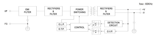
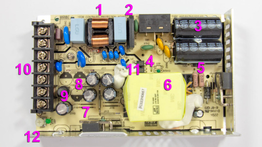
The input voltage is supplied to the input node: RF interference filter (1), a pulse surge limiter (varistor), then the voltage goes to the diode bridge (2) and two input electrolytic capacitors (3). The input voltage selector is also located here. Flyback, built on a MW03A controller (4, installed on the back side of the board) and a power switch (5) on a N-channel MOSFET transistor MMF60R290P. Unfortunately, there is no information about the controller on the Internet. The transistor has a channel resistance of 0.29 ohms at 650 volts and 13 amps. The transformer (6) is entirely covered by the casing, so it is unclear what core material is used. The output rectifier (7) is built using a Schottky diode HBR20150 in a TO-220F package screwed to the side wall and covered with casing. It is basically dual 150V 10A diodes connected in parallel. After the diode there are four output electrolytic capacitors (8) and an additional LC filter. Here (12), there is a small output voltage indicator (green LED) and a regulator (tuning resistor) for adjusting the output voltage. Input and output circuits are connected through a shared screw 7-terminal block (10). 3 terminals for the input line, neutral, and ground wires, and 2 in parallel for common and +24V output.
The main electrolytic capacitors are designed for operating temperatures up to 220°F (105°C), Rubycon. Two optocouplers (11) are installed in the feedback circuit, most likely with phototransistors transmitting control signals from the low-voltage output to the high-voltage input side.
The board has a few cutouts to increase the dielectric strength between the high-voltage and low-voltage sides of the circuit.
The picture shows that the board has three unused spots for storage output capacitors (8), most likely used in the other power supplies of the same series but with different output voltages.
Test conditions
Most tests use metering circuit #1 (see appendices) at 80°F (27°C), 70% relative humidity, and 29.8 inHg pressure.
The measurements were performed without preheating the power supply with a short-term load unless mentioned otherwise.
The following values were used to determine the load level:

Output voltage under a constant load

The high stability of the output voltage should be noted.
Power-on parameters
Powering on at 100% load
The power supply is turned off at least 5 minutes before the test, with a 100% load connected.
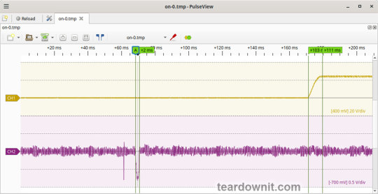
The oscillogram of switching to a 100% load is shown below (channel 1 is the output voltage, and channel 2 is the current consumption from the grid):
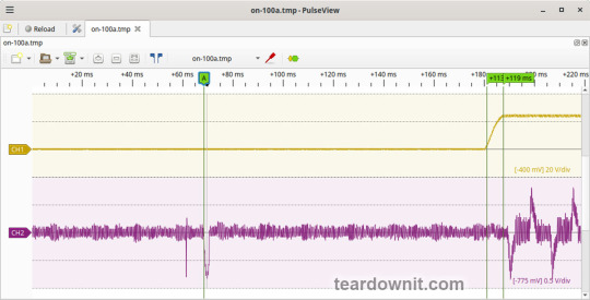
The picture shows three distinguishable phases of the power-on process:
The pulse of the input current charging the input capacitors when connected to the grid has an amplitude of about 7.5 A and a duration of 2 ms.
Waiting for the power supply control circuit to start for about 100 ms.
(Output Voltage Rise Time) Starting the converter, increasing the output voltage, and entering the operating mode) is 8 ms.
(Turn On Delay Time) The entire process of entering the operating mode from the moment of powering on) is 119 ms.
(Output Voltage Overshoot) Output voltage overshoot is absent; the switching process is aperiodic.
Powering on at 0% load
The power supply is turned off at least 5 minutes before the test, with a 100% load connected. Then, the load is disconnected, and the power supply is switched on.
The oscillogram of switching to a 0% load is shown below:
The picture shows three distinguishable phases of the power-on process:
The pulse of the input current charging the input capacitors when connected to the grid has an amplitude of about 7 A and a duration of 2 ms.
Waiting for the power supply control circuit to start for about 103 ms.
(Output Voltage Rise Time) Starting the converter, increasing the output voltage, and entering the operating mode) is 8 ms.
(Turn On Delay Time) The entire process of entering the operating mode from the moment of powering on) is 111 ms.
(Output Voltage Overshoot) Output voltage overshoot is absent; the switching process is aperiodic.
Power-off parameters
The power supply was turned off at 100% load, and the input voltage was nominal at the moment of powering off. The oscillogram of the shutdown process is shown below:

The picture shows two phases of the shutdown process:
(Shut Down Hold Up Time) The supply continues to operate due to the input capacitors holding charge until the voltage across them drops to a certain critical level at which maintaining the output voltage at the nominal level becomes impossible is 31 ms.
(Output Voltage Fall Time) Reduction of the output voltage, stopping voltage conversion, and accelerating the voltage drop is 21 ms.
(Output Voltage Undershoot) Output voltage undershoot is absent, and the shutdown process is aperiodic.
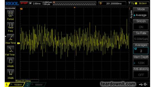
Ripple voltage and current
100% load
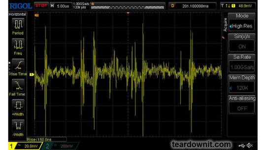
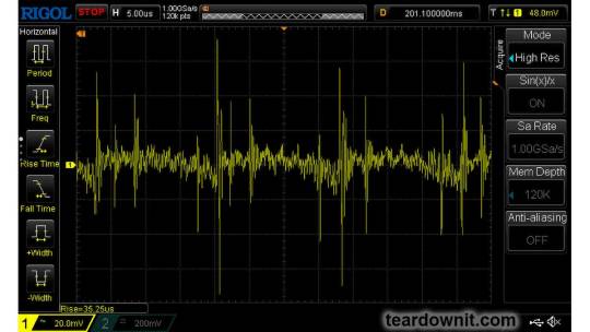
The diagram of the current draw from the grid at 100% load is shown in the oscillogram below. The amplitude of the current is about 7.5 A:
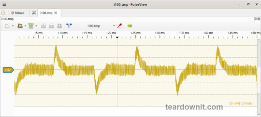
Low-frequency output voltage ripple is under 30 mV (see the oscillogram below):

Output voltage ripple at the converter frequency is under 30 mV (see the oscillogram below):

75% load
Output voltage ripple at the converter frequency is under 30 mV (see the oscillogram below):
Low-frequency output voltage ripple is under 30 mV (see the oscillogram below):

50% load
Output voltage ripple at the converter frequency stays below 10 mV; see the oscillogram (11):
10% load

0% load
No-load current consumption was measured with a multimeter, which is 60 mA RMS.
(Power Consumption) The first assumption of excessive standby power draw of more than 7 W is wrong since the current in this mode is predominantly reactive. Indeed, the input filter in the circuit contains two capacitors with a capacitance of 0.68 μF each; these low-frequency capacitors are connected in parallel, i.e., an equivalent capacitance of 1.36 μF is connected to the input terminals. A simple calculation shows that the current through these capacitors should be equal to Ic=120×2×pi×60×1.36e-6=61.5 mA. A slight difference from the measured value can be explained by the deviation of the actual parameters from their nominal values and measurement error.
Measuring the exact active power consumption at a 0% load with a basic set of instruments (oscilloscope, multimeter, etc.) is impossible.
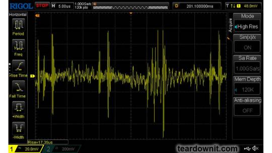
Output voltage ripple at the converter frequency is under 20 mV (see the oscillogram below):

The amplitude of low-frequency output voltage ripples is about 25 mV (see the oscillogram below):

Dynamic characteristics
A mode with periodic switching between 50% and 100% load was used to evaluate the dynamic characteristics. The process oscillogram is shown below (17):

It is evident that the supply’s response to loading changes is close to aperiodic, and there is no overshoot, which indicates a good stability margin. The magnitude of the response to load changes is within 200 mV.
Overload protection
The claimed protection type is "hiccup mode, recovers automatically after fault condition is removed". This was confirmed during testing. When a short circuit occurs, the power supply periodically tries to turn back on and, if the overload is still present, turns off again until the next attempt. This operating mode reduces energy losses and heating during overload. Still, it does not allow the parallel connection of multiple power supplies with a common output.
The output current for the overload protection to kick in is 8.5 A.
Input circuit safety assessment
(Input discharge) Safety assessment is based on the discharge time constant of the input circuits when disconnected from the grid; the value is 0.384 s. This means that when operating on a 120 V input voltage, the time required to discharge the input circuits to safe values (<42 V) will be 0.61 s:

Important: The result is valid for this particular power supply unit; it was obtained for testing purposes and should not be taken as a safety guarantee.
Thermal modes
When operating with no load connected, no component overheating had been noticed.
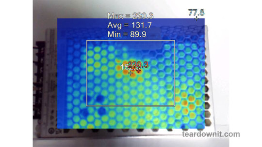
When operating under load, the input diode bridge heats up most noticeably.
With a load of 90% and the top cover closed, the case heats up to approximately 200°F; the hottest spot is located in the area of the diode bridge rectifier.
With a load of 95% and the lid closed, the case temperature reaches 230°F:
The temperature of the bridge rectifier itself is a dangerous 250°F:
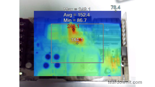
Somewhere around these load values, the power supply goes into a pulse-power-limiting mode and remains in this state either until the load drops or until it cools down. Then this 'heat up', 'limit power', 'cool down', and 'turn back on' cycle repeats.
Other things to consider:
Hot summer weather will decrease the maximum sustainable power output this supply can provide even more.
The tests were conducted with unobstructed air access to the housing for cooling; any changes may increase the heating.
This means that the power supply cannot handle its rated load for a prolonged period with no forced ventilation, and the load should be limited to 5.5 or even 5.0 A.
Conclusions
The reviewed power supply unit has characteristics generally consistent with those declared by the manufacturer, except for the long-term output power, which should be around 120 W.
The build quality is decent; no components clearly unsuitable for the general application, power draw, current, voltage, or temperature were found in the circuit.
The stability of the output voltage should be especially noted.
0 notes
Text
Understanding Circuit Board Electronic Components: A Comprehensive Guide
In today's digital world, electronic devices have become an essential part of our daily lives. But what makes these devices tick? At the heart of every electronic device lies a circuit board—a masterpiece of tiny electronic components working together to perform complex tasks. In this article, we’ll dive deep into the fascinating world of circuit board electronic components, exploring each element’s role and how they contribute to the overall functionality of the device.
What is a Circuit Board?
A circuit board, often referred to as a PCB (Printed Circuit Board), is a flat board used to mechanically support and electrically connect various electronic components. These components work in unison to perform a specific task. Think of the circuit board as the skeleton and nervous system of an electronic device—it holds everything together and allows communication between parts.
Types of Circuit Boards
Single-sided PCB: Has one layer of conducting material.
Double-sided PCB: Contains two layers for components and connections.
Multi-layer PCB: Complex boards with multiple layers for advanced applications.
The Role of Electronic Components on a Circuit Board
Every electronic device you interact with is powered by a carefully designed circuit board filled with various components. These components might be tiny, but each one has a critical role in the operation of the device. Here's a breakdown of the most important electronic components you’ll find on a typical circuit board.
1. Resistors
Resistors are fundamental components that control the flow of electrical current. They resist the flow of electrons, hence the name "resistor." Their primary function is to reduce current flow, adjust signal levels, and divide voltages in a circuit. Without resistors, circuits would allow too much current to flow, potentially damaging other components.
Types of Resistors
Fixed resistors: Have a set resistance value.
Variable resistors: Allow adjustment of the resistance.
2. Capacitors
Capacitors store and release electrical energy in a circuit. They are often compared to small rechargeable batteries that quickly charge and discharge. Capacitors help smooth out fluctuations in voltage, filter noise, and store energy for future use.
Common Uses of Capacitors
Energy storage
Signal filtering
Voltage stabilization
3. Inductors
Inductors are components that store energy in a magnetic field when electrical current flows through them. They resist changes in current and are typically used in circuits to filter signals, manage power, and store energy.
Applications of Inductors
Power supplies
Radio frequency circuits
Noise suppression in circuits
4. Diodes
A diode is like a one-way valve for electricity, allowing current to flow in only one direction. They are vital in circuits to prevent reverse currents, which can damage components.
Types of Diodes
Light-emitting diodes (LEDs): Produce light when current flows through.
Zener diodes: Regulate voltage within a circuit.
5. Transistors
The transistor is a versatile component used to amplify or switch electronic signals. In essence, transistors are like tiny switches that turn signals on and off rapidly, making them essential in modern electronics.
Types of Transistors
NPN transistors: Allow current flow when a small voltage is applied to the base.
PNP transistors: Conduct when the base is negatively charged.
How Circuit Board Components Work Together
In a circuit, each component has a specific role, and together they form a cohesive system. For example:
Capacitors and resistors may work together to filter signals or smooth out voltage fluctuations.
Transistors and diodes ensure that signals are amplified or directed properly.
Integrated circuits handle the complex tasks, processing data, and controlling the overall system.
Choosing the Right Components for Your Circuit Board
When designing or repairing a circuit board, choosing the correct components is crucial. Some factors to consider include:
Voltage requirements
Power consumption
Signal type and frequency
Physical size and compatibility
Conclusion
Circuit boards are an integral part of any electronic device. The various components on the board each play a specific role in ensuring the device functions as intended. Understanding these components, from resistors to integrated circuits, is essential for anyone working with electronics, whether you're designing a new system or troubleshooting an existing one.
1 note
·
View note
Text
Infineon launches PSoC™ 4000T, ultra-low power microcontroller
【Lansheng Technology News】Infineon Technologies AG recently announced the launch of the PSoC™ 4000T series of microcontrollers (MCUs). This new MCU series enables best-in-class low-power capacitive sensing solutions with excellent signal-to-noise ratio, water resistance and multiple sensing functions, as well as the highest reliability and robustness.
The PSoC 4000T MCU expands the Arm® Cortex®-M0+-based PSoC 4 MCU product lineup and features Infineon’s fifth generation high-performance CAPSENSE™ capacitive sensing technology. Compared with previous generations of products and similar solutions, the new generation technology improves signal-to-noise ratio (SNR) performance by 10 times and reduces power consumption to 1/10.
PSoC 4000T touch-sensing capabilities enable human-machine interface (HMI) operation at low power and standby power, optimizing Always-on touch-sensing designs and extending battery life in battery-powered products. Designers can now take advantage of the wide range of sensing support provided by PSoC 4000T, such as proximity, humidity, temperature and ambient light sensing. The fifth generation CAPSENSE technology provides better designs for interactive user interfaces, such as proximity sensing and gestures, capacitive sliders, capacitive touch pads, small-size touch screens, wear detection and liquid level detection, etc.
About the PSoC 4000T Series
For designs based on PSoC 4000 and PSoC 4000S, the PSoC 4000T series provides an easy upgrade path through software and algorithm package compatibility, allowing them to also use advanced fifth-generation CAPSENSE technology. The PSoC 4000T series is suitable for a variety of low-power applications, including wearable devices, hearable devices, smart connected IoT devices, etc.
ModusToolBox™
Infineon's ModusToolbox™ software platform provides a series of development tools, libraries and embedded operating algorithm resources to achieve a flexible and comprehensive development experience, and integrates the PSoC 4000T series in the latest software version. ModusToolbox supports a variety of different use cases, including consumer IoT, industrial, smart home, wearables, and many others.
Lansheng Technology Limited, which is a spot stock distributor of many well-known brands, we have price advantage of the first-hand spot channel, and have technical supports.
Our main brands: STMicroelectronics, Toshiba, Microchip, Vishay, Marvell, ON Semiconductor, AOS, DIODES, Murata, Samsung, Hyundai/Hynix, Xilinx, Micron, Infinone, Texas Instruments, ADI, Maxim Integrated, NXP, etc
To learn more about our products, services, and capabilities, please visit our website at http://www.lanshengic.com
0 notes
Text
A Comprehensive Guide to the GATE Electrical Engineering Syllabus
Preparing for the Graduate Aptitude Test in Engineering (GATE) in the field of Electrical Engineering requires a solid understanding of the syllabus and a well-structured study plan. The GATE syllabus is designed to cover a wide range of topics within the field to assess your knowledge and skills. Here's a comprehensive guide to the GATE Electrical Engineering syllabus:
1. Engineering Mathematics:
Linear Algebra: Matrix algebra, systems of linear equations, eigenvalues and eigenvectors.
Calculus: Limits, continuity and differentiability, partial derivatives, maxima and minima, sequences and series, Taylor series.
Differential Equations: First-order equations (linear and nonlinear), higher-order linear differential equations, Laplace transforms.
2. Electric Circuits:
Circuit Elements: Resistors, inductors, capacitors, ideal independent and dependent voltage and current sources.
Kirchhoff's Laws: Analysis of resistive circuits, nodal and mesh analysis, superposition, Thevenin and Norton theorems.
AC Circuits: Phasors, sinusoidal steady-state analysis, power factor, three-phase circuits.
3. Electromagnetic Fields:
Electrostatics and Magnetostatics: Coulomb's law, Gauss's law, Biot-Savart law, Ampere's law.
Maxwell's Equations: Differential and integral forms, electromagnetic wave propagation, Poynting vector.
4. Signals and Systems:
Signal Classification: Continuous-time and discrete-time signals, periodic and aperiodic signals.
System Analysis: Linearity, time-invariance, causality, stability, impulse response, convolution.
5. Electrical Machines:
Transformers: Single-phase and three-phase transformers, efficiency, regulation.
DC Machines: Construction, characteristics, starting and speed control.
AC Machines: Synchronous and induction machines, principles of operation, characteristics, power factor correction.
6. Power Systems:
Power Generation: Thermal, hydro, nuclear, and renewable sources.
Transmission and Distribution: Line parameters, load flow analysis, economic operation, fault analysis, protection.
7. Control Systems:
Mathematical Modeling: Transfer function, block diagram, signal flow graph.
Time Response Analysis: Standard test signals, steady-state errors, stability.
Frequency Response Analysis: Bode plots, Nyquist plots, root locus.
8. Electrical and Electronic Measurements:
Measurement Basics: Accuracy, precision, errors, standards.
Measurement Devices: Ammeters, voltmeters, bridges, oscilloscopes, transducers.
9. Analog and Digital Electronics:
Semiconductor Devices: Diodes, transistors, operational amplifiers.
Analog Circuits: Amplifiers, oscillators, filters, voltage regulators.
Digital Circuits: Logic gates, combinational and sequential circuits, ADCs and DACs.
10. Power Electronics:
Semiconductor Switches: Diodes, thyristors, MOSFETs, IGBTs.
Converter Topologies: Rectifiers, inverters, choppers, voltage regulators.
11. Electric and Magnetic Fields:
Electrostatics and Magnetostatics: Gauss's and Ampere's laws, dielectric and magnetic materials.
Maxwell's Equations: Integral and differential forms, electromagnetic wave propagation.
12. Signals and Systems:
Continuous and Discrete Signals: Fourier series and transform, Laplace transform, Z-transform.
System Analysis: Linear time-invariant systems, convolution, stability, causality.
13. Control Systems:
Time Domain Analysis: Stability, transient and steady-state response.
Frequency Domain Analysis: Bode plots, Nyquist plots, root locus, compensation techniques.
14. Power Systems:
Power Generation: Thermal, hydro, nuclear, and renewable sources.
Transmission and Distribution: Fault analysis, voltage and frequency control, load flow studies.
15. Analog and Digital Electronics:
Diodes, Transistors, and Amplifiers: Diode circuits, small signal analysis of BJT and FET, feedback amplifiers.
Digital Electronics: Logic gates, combinational and sequential circuits, ADCs and DACs.
16. Electric and Magnetic Fields:
Electrostatics: Gauss's law, boundary conditions, Poisson's and Laplace's equations.
Magnetostatics: Ampere's law, Biot-Savart law, magnetic materials.
17. Power Systems:
Power Generation: Types of power plants, load characteristics, economics of power generation.
Protection and Switchgear: Relays, circuit breakers, fuses, protection schemes.
18. Power Electronics:
Power Semiconductor Devices: Diodes, thyristors, MOSFETs, IGBTs.
Converters: AC-DC converters, DC-DC converters, inverters.
19. Electrical Machines:
Transformers: Construction, regulation, efficiency.
Synchronous Machines: Characteristics, voltage regulation, parallel operation.
Induction Machines: Construction, characteristics, starting and speed control.
1 note
·
View note
Link
BAV99 Series 100 V 215 mA Surface Mount High Speed Switching Diode - SOT-23
1 note
·
View note
Photo


So @pigeontheoneandonly tagged me with a WIP meme and explicitly mentioned my guitar rig. Thanks for thinking of me!
If @citadelsushi, @berryshiara @swaps55 @ferusaurelius @faith-less-one @ooachilliaoo or any of my mutuals want to share what they’ve been working on (doesn’t have to be a stupid expensive guitar set up :P) please tag me back so I can see!
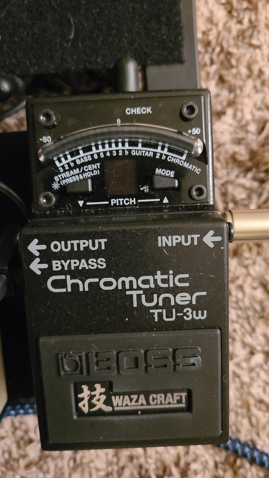
Above are the pedals in a rough layout of my signal path.
The tuner first, which can also function as a standby since when the pedal is engaged no sound gets through.
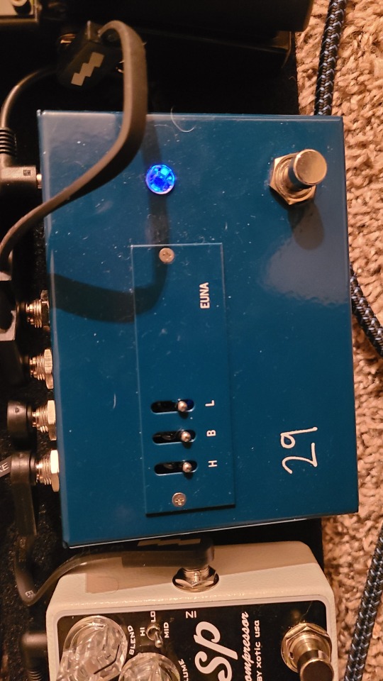
The EUNA from 29 Pedals second. This is a weird part of the signal chain that I don’t understand super well, but TL;DR it helps ensure my signal is strong enough to deal with the resistance of all the other stuff that comes between the guitar and the amp.
In a loop that bypasses all of EUNA’s functions, I keep my Hellephant. Fuzz is the first outboard effect ever made for guitar, and it wasn’t designed to see anything but direct guitar signal, so it needs a signal path seperate from the EUNA.
Next is my Xotic SP (small pedal) Compressor. Compression can be helpful for technical passages where your technique isn’t quite up to snuff. It levels out the signal, loosing some of the dynamic range (quiet-to-loud range) but also evens out any picking or plucking, which can be useful for some extended technique stuff. It can also tame the crazy volumes that can come out of my fuzzbox, which is helpful when I don’t want to blow my eardrums out.
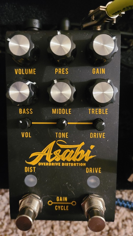
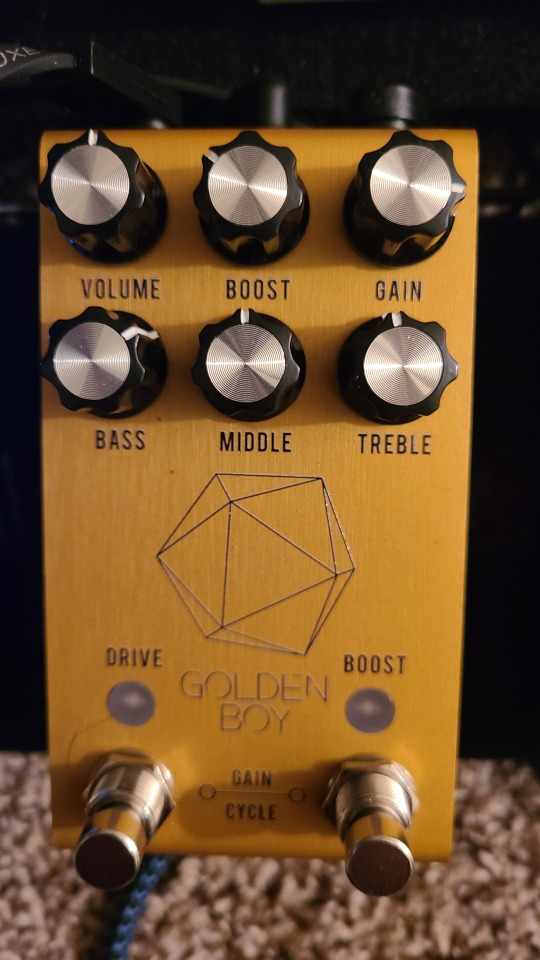
Now we have two double gain stages, the Jackson Audio Asabi and Golden Boy. The Asabi is Mateus Asato’s signature pedal, and the Golden Boy is Joey Landreth’s. The Asabi features a overdrive circuit followed by a ‘modern high-gain distortion’ circuit and a suite of other wild and fun features. The Golden Boy has the same concept, but it features a ‘distortion free’ boost and a so called ‘transparent’ or low-distortion overdrive modeled after the old Marshall Bluesbreaker pedal. Each of these 4 gain-stages have 4 different clipping diodes, which allow you to tailor at what volume the guitar starts to sound clipped/distorted, along with a number of other features. I’d try and better explain, but there are several great demos up on youtube if you’re curious.
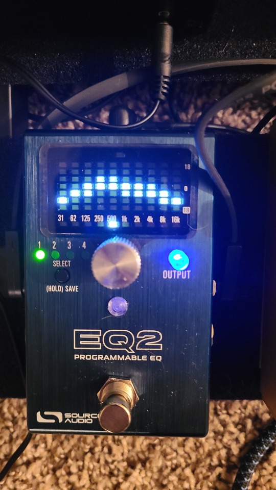
Next is the Source Audio EQ2 10 band graphic equalizer. I don’t use this much, but it has 4 customizable presets and a noise gate, which can help cut down on hum. Also useful if you find yourself plugged into an unfamilar amp or guitar and the sound isn’t quite right. Very powerful, but I spend too long fiddling with it so I mostly just leave it alone.
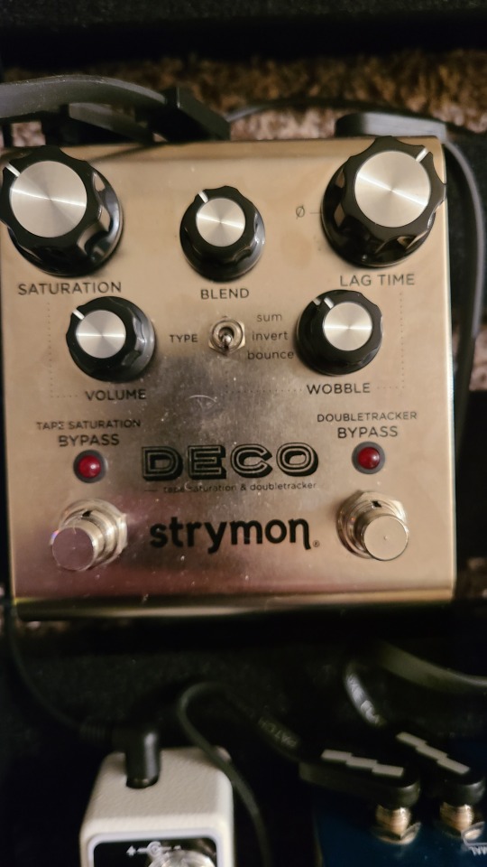
Next is the Strymon Deco. I can’t really explain this one, but its a saturation/compression/vibe/flanger/chorus/delay pedal and you’ll just have to trust that that makes sense or watch Strymons proprietary video on its release because I don’t have time to explain all that. TL;DR it pretends to be two different tape decks and does many things.
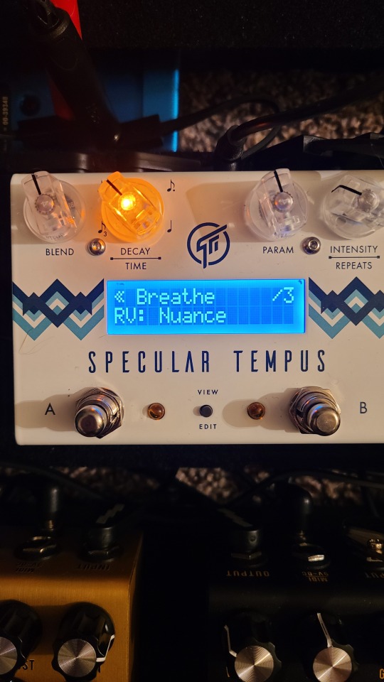
GFI systems Specular Tempus is slightly easier to explain, but not much. This is a reverb/delay pedal with 4 banks of 16 double customizable presets. It can do a wide array of reverb and delay sounds, including modulating or transposing features and doesn’t really sound like natural room reverb at all. It also has a limited number of settings where it is both delay and reverb simultaneously.
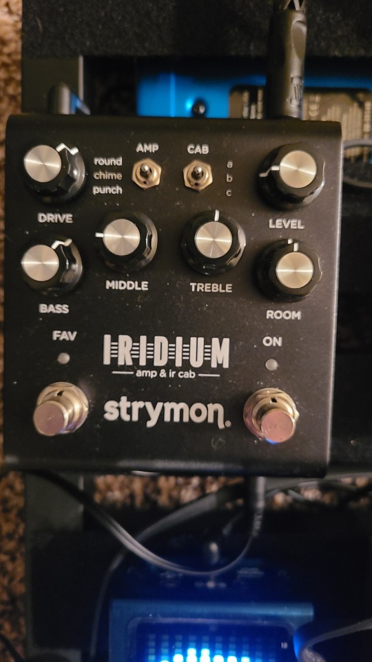
Last in the pedal chain is the Strymon Iridium. I had originally thought I wouldn’t need an amp to play because of this beauty, but unfortunately it requires powered speakers and all mine are designed to get their power from the amp, which the Iridium can’t do. It has 3 functions. It can replicate 3 different amp heads (arguably the 3 most recorded guitar amps in history.) It can make those amps sound as though they are coming from any of 3 speaker cabinets (3 per amp, for a total of 9 different ones loaded in.) And it has a truly remarkable “natural” room reverb function as well. It also has a headphones jack, which has inabled me to practice in silence while I waited for my new amp to arrive.


So above are the guitar I play the most currently and below that my new amp!
The guitar is styled after the famous Fender Stratocaster, but is in fact an Ernie Ball Cutlass.
The amp is a new hand wired VOX AC30 head, pictured here next to my VOX 1x12″ extension cabinet (celestion greenback speaker) and my EVH 5150 1x12″ speaker (celestion vintage 30 speakers.) I haven’t even plugged this in yet (well, I tested to make sure power works) but every time I have the time to play its late enough I don’t want to disturb the neighbors. HOWEVER a little history and the reason I chose the AC30:
The AC30 is one of the amps of legend. It was the amp the Beatles played on the Ed Sullivan Show at the start of the British Invasion. It’s the amp behind Brian May of Queen and all of the iconic solos and guitar sounds (okay, maybe not all but there are tons of pictures of him on stage with it so cut me some slack.) Just off wikipedia we can add the Rolling Stones, the Yardbirds, the Kinks, Dire Straights, Radiohead, and Edge of U2. After sitting around with the Iridium (which features an AC30 amp modeler) I decided if I was going to buy another guitar amp, it would have to be either the original VOX or a recreation of the circuit. There are several companies that do AC30 sound-a-likes: Morgan, Badcat, Matchless... I was on a Morgan preorder list until the hand wired AC30 came up for sale for $500 cheaper, so now I am the (presumably) proud owner of an AC30!
Sorry there’s no great place to put a cut in this one! Long post alert :P
16 notes
·
View notes
Text
12 unique advantages of LED lighting
Energy Conservation and sustainable development is no longer a selective issue, but it is the only way of world’s future development. Led as the representative of the new light source lighting to replace the traditional light source, it is causing a great change in lighting industry. Driven by innovative technology, the new lighting products are constantly being updated, from incandescent lamps to energy-saving lamps, halogen lamps to LED lamps. The lighting products have achieved energy-saving upgrades, and at the same time, they have also been improved in comfort, the lighting effect is also more diverse. As the representative of the Green energy-saving light source, LED lighting has become the most potential market in the industry. Compared with the more mature light source, what are the leading advantages of LED? The following is a brief introduction by the author.
12 unique advantages of LED lighting
In 1923, the scientist O.W. Lossew discovered that the P-N junction of silicon carbide had unidirectional conductivity and luminescence; around 1955, R. J. Haynes presented a study on P-N junction of semiconductor germanium, G. A. Wolff studied the luminescence of Gallium Phosphide; in 1968, the first red LED was produced by Monsanto and HP in the United States, making it an electronic product.
(1) energy conservation: the spectrum of leds is almost entirely concentrated in the visible light band, with a luminous efficiency of 80 to 90 per cent. The results show that the
luminous efficiency of the ordinary incandescent lamp is 12 lm/w, the life is less than 2000 hours, and the luminous efficiency of the spiral fluorescent lamp is 60 LM/W, with a life span of less than 8,000 hours, the T5 fluorescent lamp has a 96 ALMW life span of about 10,000 hours, while the 5 mm diameter white LED has a life span of 20 something 28 LLMW and can last more than 100000 hours. Some also predict an infinite upper limit on the lifetime of future leds.
The conventional wisdom is that cfls can save up to four fifths of energy, but leds can save up to a quarter more than cfls, a far greater innovation for Solid State Lighting. In addition, LED also has other advantages, high-quality light, basically no radiation, is a typical green lighting source, reliable and durable, very low maintenance costs, and so on. Because LED has the above other solid light source is unable to match the characteristics, 10 years later LED lighting industry will be the mainstream light source.
(2) safety and Environmental Protection: LED working voltage is low, mostly 1.4 something 3v; ordinary LED working current is only 10mA, ultra-high brightness is only 1a. Led in the production process do not add “Mercury” , do not need to inflate, do not need glass shell, impact resistance is good, earthquake resistance is good, not broken, easy to transport, very environmental protection, known as “Green Energy” .
(3) Long Life: LED small size, light weight, shell for epoxy packaging, not only to protect the internal chip, but also has the ability to light transmission and spotlight. Leds typically have a lifespan of between 50,000 and 100,000 hours, and because leds are semiconductor device, even frequent switches don’t affect their lifespan. At present, incandescent lamps, fluorescent lamps and energy-saving fluorescent lamps are mainly used for household lighting.
(4) Fast Response: the response frequency τmc of leds is related to the lifetime τmc of a few carriers injected. For example, for leds made of GaAs material, the response frequency of τmc is about 16 something 160 mhz in the range of 1 something 10 ns, this high response rate is sufficient for displaying a 6.5 mhz video signal, which is one of the key factors in achieving a video LED large screen.
At present, the lowest LED response time has reached 1 microsecond, the general for a few milliseconds, about the common light source response time 1/100. Therefore, it can be used in many high-frequency environments, such as car brake lights or state lights, can shorten the braking time of the vehicle behind the car, thus improving safety.
LED light source powerful advantage
(5) High luminous efficiency: incandescent lamps and halogen lamps have a luminous efficiency of 12-24 LM/W (Lumen/w) , fluorescent lamps have a luminous efficiency of 50 Something 70 lm/w, sodium lamps have a luminous efficiency of 90 Something 140 LM/w, and most electricity consumption becomes heat loss. The light efficiency of LED can reach 50 Something 200 LM/W after improvement, and the light has good monochromatic, narrow spectrum, no filtering can be directly issued colored visible light.
(6) small size of LED components: more convenient for the layout and design of various equipment, and can better realize the effect of “see the light but not the light source” in night scene lighting.
(7) high concentration of LED light energy: concentrated in the smaller wavelength window, high purity.
(8) LED light directivity is strong: brightness attenuation is much lower than traditional light source.
(9) LED can be driven by low-voltage DC power: with the advantages of small load, weak interference, the use of lower environmental requirements.
(10) Better control of the composition of the Luminescence Spectrum: This makes it suitable for local or focal lighting in museums and exhibition halls.
(11) The size of the semiconductor luminescent layer and the List of semiconductor materials forbidden band can be controlled: thereby emitting light of various colors and having a higher degree of color.
(12) High color rendering: will not cause harm to the human eye.
In conclusion: as an emerging technology sector, the light-emitting diode industry is still in a fast developing stage, and we are pleased with the progress of Science and Technology, but we also have to realize that both the technology sector and the regulation of the industry, compared with the traditional light source, they are not mature and sound. There is still a long way to go before the LED can truly replace the traditional light source. We believe that by promoting the healthy and orderly development of the entire industry, continuously accelerating the pace of application and gradually transforming the traditional industry, and promoting the adjustment of the industrial structure, it will open energy-saving green quality of life for people.
Sousce by: https://www.recolux.cn/12-unique-advantages-of-led-lighting/
1 note
·
View note