#High speed small signal diodes
Explore tagged Tumblr posts
Text
https://www.futureelectronics.com/p/semiconductors--discretes--diodes--small-signal-diodes/sstpad5-lf-calogic-1036092
Application of signal diode, switching circuits, types of signal diode
SSTPAD5 Series 1.5 V 10 mA Surface Mount Pico Amp Diode - SOT-23
#Calogic#SSTPAD5-LF#Diodes#Small Signal Diodes#application#switching circuits#diode small signal resistance#low voltage signals#diode voltage drop#High speed small signal diodes#PN junction diode#Schottky diode
1 note
·
View note
Text
https://www.futureelectronics.com/p/semiconductors--discretes--diodes--switching/1n4148w-7-f-diodes-incorporated-4129355
Diodes Incorporated, 1N4148W-7-F, Diodes, Switching Diodes
1N4148W Series 2 A 100 V 400 mW Surface Mount Fast Switching Diode - SOD-123
#Diodes Incorporated#1N4148W-7-F#Diodes#Switching Diodes#Power supplies#chip#higher switching speed#pin diode switch#Fast#digital logic circuit#Small signal diode#High-speed switching#Small Surface-Mounted#Microwave diode
1 note
·
View note
Text
Thyristor Rectifiers: An In-Depth Overview
Thyristor rectifiers are pivotal in the realm of power electronics, providing crucial capabilities for converting alternating current (AC) to direct current (DC). These devices, integral to many industrial and commercial applications, harness the unique properties of thyristors to deliver efficient and controlled power conversion. This article explores the core concepts, advantages, and applications of thyristor rectifiers, offering a comprehensive understanding of their role in modern power systems.
What is a Thyristor Rectifier?
A thyristor rectifier is a type of rectifier circuit that utilizes thyristors—semiconductor devices known for their ability to handle high voltages and currents. Unlike traditional diodes, thyristors can be controlled and turned on or off by applying a gate signal, which allows for precise regulation of power.
How Thyristor Rectifiers Work
AC Input: The thyristor rectifier receives an alternating current input, which alternates between positive and negative phases.
Thyristor Operation: A thyristor is a four-layer, three-junction device with four terminals: anode, cathode, gate, and a small gate terminal for triggering. During the positive half-cycle of the AC input, the thyristor can be triggered into conduction by a gate pulse. Once triggered, it remains in the conducting state until the AC input goes through a zero-crossing point.
Rectification: As the AC input varies, the thyristors alternate between conducting and blocking states, effectively converting the AC into a pulsating DC output. The output DC voltage is controlled by adjusting the firing angle of the thyristors, which determines when during each cycle the thyristor will conduct.
Controlled Firing: The timing of the gate pulses—referred to as the firing angle—is crucial. By varying this angle, the average DC output voltage can be controlled, allowing for dynamic power regulation.
Benefits of Thyristor Rectifiers
Thyristor rectifiers offer several significant advantages:
High Power Handling: Thyristors are designed to handle high voltages and currents, making them suitable for demanding applications.
Precise Control: The ability to control the firing angle allows for precise adjustment of the DC output voltage, which is essential for applications requiring variable power.
Efficiency: Thyristor rectifiers provide efficient power conversion with minimal energy losses, improving overall system performance.
Durability: Thyristors are robust and reliable, capable of withstanding harsh operational environments and high power levels.
Applications of Thyristor Rectifiers
Thyristor rectifiers find applications across various sectors:
Industrial Motor Drives: Thyristor rectifiers are used to control the speed and torque of electric motors in industrial settings, enabling precise motor control.
HVDC Transmission Systems: In high-voltage direct current (HVDC) systems, thyristor rectifiers convert AC power into DC for long-distance transmission, reducing losses and improving efficiency.
Power Supplies: Thyristor rectifiers are employed in power supply units to convert AC from the grid into stable DC for electronic devices and systems.
Battery Charging: They are used in battery chargers to regulate the charging current, ensuring efficient and safe charging of batteries.
Welding Equipment: Thyristor rectifiers provide the controlled DC necessary for electric arc welding, ensuring consistent welding quality and performance.
Challenges and Considerations
Despite their advantages, thyristor rectifiers present certain challenges:
Complex Control Systems: The precise control of firing angles and synchronization with the AC supply can be complex and requires sophisticated control circuitry.
Thermal Management: High-power applications can generate significant heat, necessitating effective cooling and thermal management to maintain reliable operation.
Harmonic Distortion: Thyristor rectifiers can introduce harmonic distortions into the power system, which may require additional filtering to mitigate.
Conclusion
Thyristor rectifiers are crucial components in modern power systems, offering efficient and controlled conversion of AC to DC. Their ability to handle high power levels, coupled with precise control capabilities, makes them invaluable in industrial motor drives, HVDC systems, power supplies, and more. As technology advances, ongoing improvements in thyristor rectifiers are likely to enhance their efficiency and applicability, solidifying their role in the future of power electronics.
0 notes
Text
LED auto lights refer to the use of LED technology for both internal and external lighting. External lighting equipment involves thermal limits and EMC issues, as well as many complex standards for unloading load tests. LED auto lights can be widely used to create an in-car environment with a service life of 50,000 hours. The structure of LED is sturdy and not easily affected by vibration, and the light output brightness will not drop significantly during use. LED car lights are suitable for various lighting applications in automotive electronics, including headlights (high beam and low beam), fog lights, taillights, brake lights, turn signals, daytime running lights, pedal lights, instrument lights, license plate lights, door lights, interior lights, width lights, navigation, entertainment systems, backlights and indicator lights.
Advantages:
1. Energy saving: The light-emitting diode directly converts electrical energy into light energy, and the power consumption is only 1/10 of that of ordinary car bulbs, which can better save fuel consumption and protect the car circuit from being burned out by excessive load current.
2. Environmental protection: There is no ultraviolet and infrared in the spectrum, low heat, no radiation, low glare, and the waste can be recycled, no pollution, no mercury, safe to touch, and it is a typical green lighting LED source.
3. Long life: There is no loose part in the lamp body, and there are no shortcomings such as easy burning of filament light, heat deposition, and light decay. Under the appropriate current and voltage, the service life can reach 80,000-100,000 hours, which is more than 10 times longer than the life of traditional light sources. (It has the characteristics of one-time replacement and lifelong use)
4. High brightness and high temperature resistance. (Electric energy is directly converted into light energy, low heat, and can be touched by hand, safe and secure)
5. Small size. The designer can change the lamp mode at will to diversify the car shape. The reason why automobile manufacturers favor LED is entirely determined by the advantages of LED itself.
6. Good stability and strong anti-seismic performance of LED: resin encapsulation, not easy to break, easy to store and transport.
7. High luminous purity, clear and bright colors, no need for lampshade filtering, and light wave error within 10 nanometers.
8. Fast response speed, no hot start time required, can emit light within microseconds, while traditional glass bulbs have a 0.3 second delay, which can prevent rear-end collisions and ensure driving safety.
Disadvantages:
1: LED headlights are more expensive than ordinary headlights. (With the continuous popularization of LED applications, prices will be further reduced)
2: It is difficult to popularize car headlights, and the heat dissipation is not good. If the heat dissipation is not properly handled, it is easy to light decay, which affects the service life of the headlights.
3: There are no industry standards issued, and the product quality is uneven. The price of the same product produced with different LEDs varies by 1-2 times. Fortunately, a small number of companies implement standards higher than the general industry standards, so product quality control is better than most companies, such as SNGL brand companies, etc.
1 note
·
View note
Text
Review, teardown, and testing of RSP-320-24 Mean Well power supply
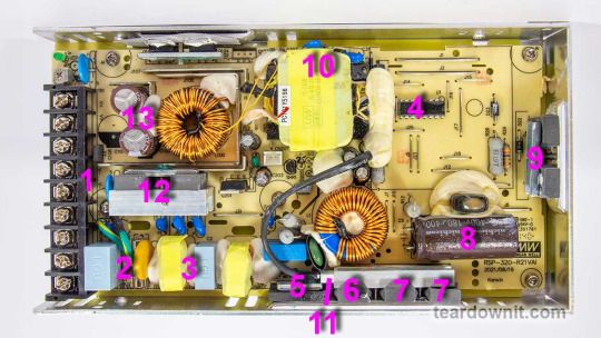
The RSP-320-24 is a 24-volt power supply with a maximum current of 13.4 amps. The supported mains voltage is from 100 to 240 volts without an additional switch. The supply measures 8.5 × 4.5 × 1¼ inches (215 × 115 × 30 millimeters), made on a printed circuit board fixed to the base's case. The top cover is perforated at the back near the connection terminals and on the front, where the cooling fan is installed. The fan starts spinning even if there's no electrical load. As the load increases, the fan speeds up, following the load current value. The fan sucks in the air and pushes it through the internal case volume to the perforated holes, including those on the side walls.
The input and output circuits are connected to a standard screw terminal block (1), from right to left: 3 terminals for the input line, neutral and ground wires, and 3 in parallel for common and +24V output. The input voltage from the terminals goes to the fuse (2), then to the pulse limiter (varistor), followed by the RF interference filter (3), and finally to the diode bridge (5). Next comes the active PFC, controlled by the PFC+PWM controller FAN4800 (4). Indeed, with a 234-volt AC power input, we get a rectified voltage on the storage capacitor (8) of 377 volts, approximately 47 volts more than without PFC Boost. The small voltage reserve is confusing since the capacitor installed is rated for 180 uF and 400 volts. All that's left is to rely on Nichicon's quality control.
The power part of the PFC is made of two parallel MOSFETs, IPP60R280P6 (7) and on an ultrafast diode 8A 600V STTH8S06D (6). The temperature sensor (11) is mounted above the PFC elements. The output voltage from the PFC is supplied to the two-transistor forward converter; the transistors are IPP60R280P6 (9) and are controlled by the same FAN4800 controller. The transformer (10) converter voltage is rectified and supplied to the LC filter. The output rectifier comprises eight diodes connected in two parallel groups (12). Total output capacitance: 2 pieces of 1000uF, 35V, designed for operating temperatures up to 220°F (105°C) (13). The output high-current circuits are reinforced with tinned copper busbars.
The control signal from the high-voltage side to the low-voltage side is transmitted through transistor optocouplers (there are two of them in the photo above the transformer hidden under a blob of the compound). One optocoupler is the primary regulation channel, and the second forms a backup channel for overvoltage protection, OVP.

The block diagram in the datasheet shows the "Active Inrush Current Limiting" node. Still, we could not find components on the board that could perform such a role. Still, the inrush current limitation element is present, marked as RTH1 on the board, and installed near the boost inductor PFC; most likely, this is an ordinary NTC.
The high-voltage part of the board, starting with the capacitor (8) and ending with the transformer leads (10), is coated on the high-voltage side with a protective composite, presumably epoxy-based, which further increases electrical safety.
There is additional insulation and a thin sheet of fiberglass between the aluminum case and the board (solder side).
The overall build quality is good.
Test conditions
Most tests use metering circuit #1 (see appendices) at 80°F (27°C), 70% relative humidity, and 29.8 inHg pressure. The measurements were performed without preheating the power supply with a short-term load unless mentioned otherwise.
The following values were used to determine the load level:

Output voltage under a constant load

The high stability of the output voltage should be noted.
Power-on parameters
Powering on at 100% load
The power supply is turned off at least 5 minutes before the test, with a 100% load connected. The oscillogram of switching to a 100% load is shown below (channel 1 is the output voltage, and channel 2 is the current consumption from the grid):
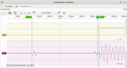
The picture shows three distinguishable phases of the power-on process:
The pulse of the input current charging the input capacitors when connected to the grid has an amplitude of about 2 A and a duration north of the mains voltage period.
Waiting for the power supply control circuit to start for about 300 ms.
(Output Voltage Rise Time) Starting the converter, increasing the output voltage, and entering the operating mode takes 8 ms.
(Turn On Delay Time) The entire process of entering the operating mode from the moment of powering on is 315 ms.
(Output Voltage Overshoot) The switching process is aperiodic; there is no overshoot.
Powering on at 0% load
The power supply is turned off at least 5 minutes before the test, with a 100% load connected. Then, the load is disconnected, and the power supply is switched on. The oscillogram of switching to a 0% load is shown below:
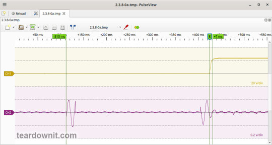
The picture shows three distinguishable phases of the power-on process:
The pulse of the input current charging the input capacitors when connected to the grid has an amplitude of about 2.2 A and a duration slightly longer than one mains period.
Waiting for the power supply control circuit to start for about 300 ms.
(Output Voltage Rise Time) Starting the converter, increasing the output voltage, and entering the operating mode takes 7 ms.
(Turn On Delay Time) The entire process of entering the operating mode from the moment of powering on is 320 ms.
(Output Voltage Overshoot) The switching process is aperiodic; there is no overshoot.
Power-off parameters
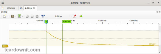
The power supply was turned off at 100% load, and the input voltage was nominal at the moment of powering off. The oscillogram of the shutdown process is shown below:
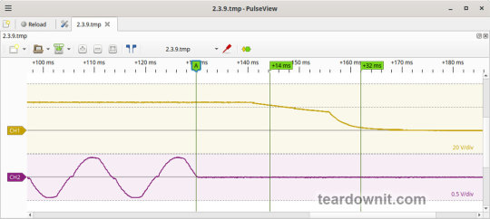
The picture shows two phases of the shutdown process:
(Shutdown Hold-Up Time) The power supply continues to operate due to the input capacitors holding charge until the voltage across them drops to a certain critical level, at which maintaining the output voltage at the nominal level becomes impossible. The phase takes 14 ms.
(Output Voltage Fall Time) Reduction of the output voltage, stopping voltage conversion, and accelerating the voltage drop takes 18 ms.
(Output Voltage Undershoot) The shutdown process is aperiodic; there is no overshoot.
Right before shutdown, the current waveform at 100% load is close to sinusoidal with an amplitude of 4.22 A.
Ripple output voltage
100% load
At 100% load, the low-frequency ripple is approximately 3 mV.

At 100% load, the ripple at the converter frequency is approximately 50 mVp-p, and the noise is 120 mVp-p.
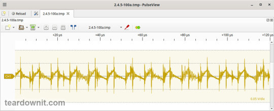
75% load
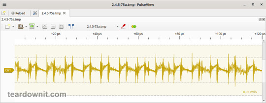
At 75% load, the low-frequency ripple is approximately 3 mV.

At 75% load, the ripple at the converter frequency is approximately 40 mVp-p, and the noise is 120 mVp-p.
50% load
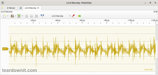
At a 50% load, the low-frequency ripple is approximately 3 mV.

At 50% load, the ripple at the converter frequency is approximately 30 mVp-p, and the noise is 70 mVp-p.
10% load
At 10% load, the low-frequency ripple is approximately 2 mV.
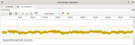
At a 10% load, the ripple at the converter frequency is approximately 20 mVp-p, and the noise is 90 mVp-p.
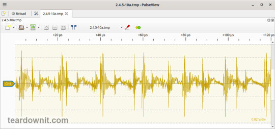
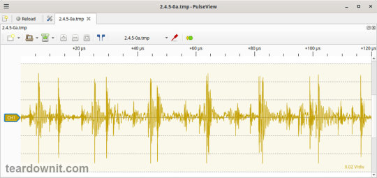
0% load
No-load current consumption measured with a multimeter: 53.5 mA.
(Power Consumption) The first assumption of excessive standby power draw of more than 6.5 watts is wrong since the current in this mode is predominantly reactive. Indeed, the input filter in the circuit contains two capacitors with a combined capacitance of 1.5 μF. Measuring the exact active power consumption at a 0% load with a basic set of instruments (oscilloscope, multimeter, etc.) is impossible.
At 10% load, the low-frequency ripple is approximately 2 mV.
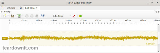
At 10% load, ripples at the converter frequency are masked by the 90 mVp-p noise.
Dynamic characteristics
TA mode with periodic switching between 50% and 100% load was used to evaluate the dynamic characteristics. The process oscillogram is shown below:
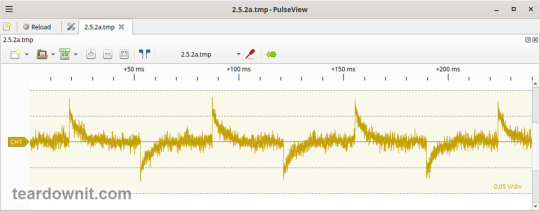
It is evident that the supply’s response to loading changes is close to aperiodic, and there is no overshoot, which indicates a good stability margin. The magnitude of the response to load changes is just 60 mV.
Overload protection
The claimed protection type is "hiccup mode, recovers automatically after fault condition is removed." This was confirmed during testing. When a short circuit occurs, the power supply periodically tries to turn back on and, if the overload is still present, turns off again until the next attempt. This operating mode reduces energy losses and heating during overload. Still, it does not allow the parallel connection of multiple power supplies with a common output.
The output current for the overload protection to kick in is 17 A.
Input circuit safety assessment
(Input discharge) Safety assessment is based on the discharge time constant of the input circuits when disconnected from the grid; the value is 0.26 s. This means that when operating on a 120 V input voltage, the time required to discharge the input circuits to safe values (<42 V) will be 0.41 s:

Important: The result is valid for this particular power supply unit; it was obtained for testing purposes and should not be taken as a safety guarantee.
The leakage current at the ground pin is less than 10 µA.
Thermal conditions
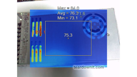
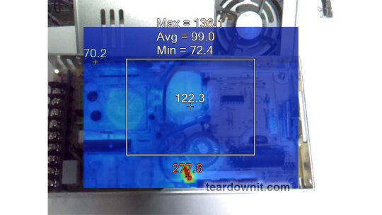
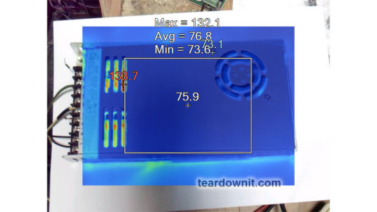
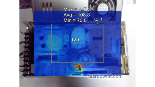
When operating with no load connected, no component overheating had been noticed. Thermograms were captured at three power levels: 80, 90, and 100%, fully assembled and with the lid removed. Thermal images show that the most loaded element of the block is the input diode bridge, and its heating seriously stands out against the background of all the other components.
Unfortunately, already at 80% load, the diode bridge heats up to an unacceptable level of 259°F (126°C), which is dangerous for long-term operation.
80% load
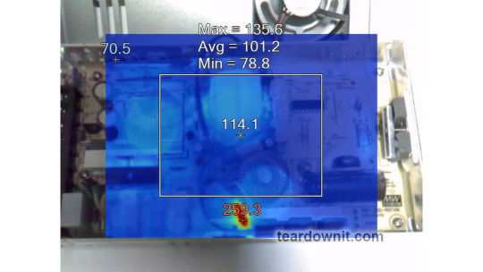
90% load
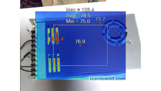
100% load
Conclusions
Overall, the RSP-320-24 is well-built: this power supply has good dynamic characteristics, low noise, and ripple, good accuracy in maintaining the output voltage, and is well put together. The load should be limited to 70–80% of the nominal for long-term operation.
Important: The results are valid for this particular power supply unit; they were obtained for testing purposes and should not be used to evaluate all the units of the same type.
0 notes
Text
Toshiba launches compact photorelay suitable for switching high-frequency signals in semiconductor test equipment

【Lansheng Technology News】On October 17, 2023, Toshiba announced today the launch of the photorelay "TLP3475W" in a small and thin WSON4 package. It can reduce insertion loss in high-frequency signals and suppress power attenuation [1], and is suitable for pin electronic devices of semiconductor test equipment that use a large number of relays and require high-speed signal transmission.
The TLP3475W uses Toshiba's optimized packaging design, which helps reduce the parasitic capacitance and inductance of the new photorelay. While reducing insertion loss, it can also improve the transmission characteristics of high-frequency signals to 20GHz (typ. value) [2] - compared with Toshiba's existing product TLP3475S, the insertion loss is reduced by about 1/3 [2].
TLP3475W adopts a small and slim WSON4 package with a thickness of only 0.8mm (typical value). It is currently the smallest [3] photorelay in the industry, and it has successfully improved high-frequency signal transmission characteristics. It is 40% thinner than Toshiba's ultra-small S-VSON4T package and supports mounting more products on the same circuit board, which will help improve measurement efficiency.
Lansheng Technology Limited, which is a spot stock distributor of many well-known brands, we have price advantage of the first-hand spot channel, and have technical supports.
Our main brands: STMicroelectronics, Toshiba, Microchip, Vishay, Marvell, ON Semiconductor, AOS, DIODES, Murata, Samsung, Hyundai/Hynix, Xilinx, Micron, Infinone, Texas Instruments, ADI, Maxim Integrated, NXP, etc
To learn more about our products, services, and capabilities, please visit our website at http://www.lanshengic.com
0 notes
Text
Exploring the World of 74HC Series Integrated Circuits: 74HC11, 74HC165, And 74HC151.
Integrated Circuits (ICs) are essential components used in almost all electronic devices today, ranging from smartphones to computers and automobiles. They consist of multiple transistors, diodes, and other components integrated into a single chip, making them small, efficient, and reliable. In this blog, we will discuss three different types of ICs - the 74HC11 Triple 3-Input AND Gate IC, the 74HC165 8-Bit Parallel In/Serial Out Shift Register IC, and the 74HC151 8-Input Multiplexer IC.
74HC11 Triple 3-Input AND Gate IC
The 74HC11 is a triple 3-input AND gate IC that can be used in various applications, including digital signal processing, data processing, and communication systems. It contains three independent gates, each with three inputs, which are connected to an internal circuit that performs the AND operation on the inputs. The outputs of the gates are complementary, which means that when one output is high, the other output is low. The 74HC11 operates at a voltage range of 2V to 6V and has a high noise immunity, making it an ideal choice for high-speed applications.
74HC165 8-Bit Parallel In/Serial Out Shift Register IC
The 74HC165 is an 8-bit parallel in/serial out shift register IC that can be used in various applications, including data storage, signal processing, and control systems. It has eight parallel input pins that can be used to load data into the shift register, and a single serial output pin that outputs the data in a sequential manner. The 74HC165 also has a clock input pin that controls the shifting of data through the register. It operates at a voltage range of 2V to 6V and has a high noise immunity, making it an ideal choice for high-speed applications.
74HC151 8-Input Multiplexer IC The 74HC151 is an 8-input multiplexer IC that can be used in various applications, including signal processing, control systems, and digital data processing. It has eight input pins and one output pin, and it selects one of the eight input signals based on the binary value applied to its three select input pins. The 74HC151 can be used as a data selector or as a function generator, making it a versatile IC. It operates at a voltage range of 2V to 6V and has a high noise immunity, making it an ideal choice for high-speed applications.
1 note
·
View note
Link
Switching diodes are a single p-n diode in a discrete package. A switching diode provides the same functionality as a switch. It has high resistance below the specified applied voltage like an open switch, whereas above that voltage it changes in a sudden way to the low resistance of a closed switch
1 note
·
View note
Link
BAV99 Series 100 V 215 mA Surface Mount High Speed Switching Diode - SOT-23
1 note
·
View note
Text
How Is The Broadband Light Source Moving Spectroscopy to UV From Near-IR?
Discharge lamps, dye lasers, and optical parametric oscillators were the only valuable sources for spectroscopy in the early 1990s or mid-1980s. However, as optical technologies evolve and their applications broaden, we have been introduced to new light sources and lasers. The broadband light source is one such type of light source that has gained popularity in optical spectroscopy.
In this blog post, we will look at what a broadband light source is, how it works, and how it opens up new opportunities for spectroscopists. So, without further ado, let's begin with a definition of a broadband light source.

What Exactly Is A Broadband Light Source?
A broadband light source, also known as a superluminescent source, is a superluminescent diode with a wavelength of emission of 700 nm and a bandwidth of 1700 nm that is perfect for OEM integration. Moreover, it is often used for multi-wavelength tests for measuring wavelength-division-multiplexing components. This implies it has a wide range of applications in the medical, telecommunications, sensing, and measurement industries.
Broadband light sources are utilized for ultrahigh-resolution optical coherence tomography, passive component testing, and multi-channel fiber Bragg grating interrogation, in addition to these applications. Now, let's take a closer look at how a broadband light source works.
Working Principle of Broadband Light Source
The working principle of a BLS is very simple. A prism or grating disperses a beam of radiation from a broadband source. The scattered radiation strikes a slit, through which a small range of wavelengths passes to reach a detector. By rotating the prism or grating, consecutive wavelengths are brought onto the slit, allowing the spectrum to be scanned.
Moreover, broadband light sources are a great pick for Near-Infrared (NI) spectroscopy due to several factors. The following are three of BLS's most notable characteristics.
A. The broadband light source's directional output enables substantially better levels of light transmission efficiency into the fiber optic cable.
B. Broadband light sources have an extremely limited spectral bandwidth because they generate coherent light, allowing them to transport data at significantly greater speeds.
C. Broadband light sources are frequently modulated directly. This is a simple and effective method of converting data to an optical signal.
Eventually, these exceptional properties play a critical role in making BLS a viable option for spectroscopy and optical fiber communication applications. Let us now proceed to the next section of this blog to learn how broadband light sources provide new opportunities for spectroscopists.
How Broadband Light Source Brings New Opportunities For Spectroscopists?
Broadband light was previously only available from discharge lamps, plasma sources, hot glow bars, or the sun for much of the last decades. Also, before the laser, one of the only ways to obtain narrowband line radiation was to utilize a low-pressure gas discharge lamp, such as a mercury or sodium lamp.
However, a new generation of comparatively robust sources, such as Supercontinuum lasers, laser-driven plasma sources, and high brightness LEDs, are finding a place in the spectroscopist's toolset.
The outstanding qualities of these broadband light sources help in the advancement and efficiency of spectroscopy. This technology is not only more advanced than traditional light sources, but it is also less expensive. All of these novel light sources are enhancing spectroscopy from the near-IR to the UV.
Moreover, based on the research and improvements being conducted on broadband light sources, we can confidently predict that we are yet to witness substantial growth in industrial applications of broadband light sources in the near future.
Inphenix is a USA-based manufacturer and supplier of innovative light source and laser devices, including swept-source, Distributed feedback lasers (DFB lasers), semiconductor optical amplifiers (SOAs), superluminescent diodes (SLDs), Gain chips, and a lot more. In addition, the company also manufactures customized devices based on your requirements. To learn more, visit the website.
1 note
·
View note
Text
Design A High Performance PON Optical Receiver

An optical receiver's structure is very simple. It consists of a photodiode that produces the electric current and an amplifier. It is much more difficult to create a high-performance optical receiver. We will now discuss some criteria for actual receivers.
There are many factors that go into the process. Signal current noise, noise coming from the photodiode (such as an avalanche dimming diode), noise from the amplifier electronics, thermal noise and dark current are all important factors.
How do you choose the right photodiode
For optical receiver applications, there are two main types of photodiodes: Avalanche and PIN.
Photodiode PIN
PIN photodiode can be extended to PN diode. But PN diode is not without its flaws. The PN diode's depletion area is too small, so the received PON Optical Receiver power must not be very high in order to generate enough current. The second flaw of PN diode is its slow response, which limits it to kilohertz applications.
These limitations were solved by PIN photodiode. The depletion area has been increased to the maximum extent possible, with most photons being absorbed in the depletion area. The intrinsic layer reduces the function capability, which increases the switching speed and photon capture area.
This improved design has the added benefit of a faster opto-electro conversion rate and more efficiency.
Avalanche photodiode
Each photon absorbed by a PIN photodiode produces an electron hole pair, which then sets one electron flowing in the circuit.
A few incident photons can result in many carriers being created and an increase in external current in Avalanche photodiodes. This is how an Avalanche photodiode does it.
This phenomenon is called avalanche multiplication. This is because a strong electric field accelerates current carriers to such an extent that they knock out valence electrons from the semiconductor lattice. With a sufficient bias voltage, an avalanche will occur.
All of these are great, but there is a downside. The carriers amplify, but the uneven nature and multiplication creates noise.
Avalanche photodiodes, while non-linear, are quite unstable. However, they perform very similarly to regular silicon photodiodes, except that they require a lower operating voltage to achieve good multiplication.
Other important performance parameters for a photodiode
Below are some key parameters for your reference.
Receptivity
Photodiode responsiveness is the ratio between incident light power and generated current. This is often expressed in Amp/Watt. This is sometimes referred to as quantum efficiency.
Dark Current
The photodiode produces dark current when there is no incident sunlight. Dark current also includes current that is generated by background radiation or the saturation current at the semiconductor junction. When used in optical communication systems, dark current can be a source for noise. Read more here: https://www.premlink.net/pl150d-3-ftth-optical-receiver-pon-pass/
1 note
·
View note
Text
Product structure of LCD (1)
https://www.topfoison.net/lcd/product-structure-of-lcd-1/
1. According to the technical classification of display screen: tft-lcd /Mono LCD(stn-fstn)/OLEDLCD:(Liquid Crystal Display)
Liquid Crystal Display (LCD) is short for Liquid Crystal Display (Liquid Crystal Display). The structure of LCD is to place Liquid Crystal in two parallel glass pieces. There are many thin vertical and horizontal wires between the two pieces of glass.The structure of the LCD is placed in the middle of the two pieces of parallel glass liquid crystal box, the substrate glass set on TFT (thin film transistor), set the color filter substrate glass on, on the TFT signal and the voltage change to control the rotation direction of the liquid crystal molecules, so as to achieve control of each pixel display emergent polarized light or not and to achieve.Create various colors based on white light passing through a color filter.The white light will form basic colors such as red, green and blue after passing through, and the light transmittance of each pixel point will be controlled by an electric current, so as to control the color of the pixel.
TFT-LCD
TFT (Thin Film Transistor) refers to the Thin Film Transistor, each LCD pixels is integrated in the Thin Film Transistor to drive behind the pixels, which can achieve high speed, high brightness, high contrast display screen information, is one of the best LCD color display device, compared with those of the STN TFT has excellent color saturation, reducing power and higher contrast, the sun still see very clear, but the downside is consumed, but also high cost.
Main features (advantages and disadvantages)
(1) good service characteristics: low voltage applications, low driving voltage, solid use safety and reliability;Flat, thin and light, saving a lot of raw materials and use space;Low power consumption, reflective tft-lcd even only about 1% of CRT, saving a lot of energy;Tft-lcd products also have many characteristics, such as specifications, size series, variety, convenient and flexible use, easy maintenance, update, upgrade, long service life and so on. Display quality from the simplest monochrome character graphics to high resolution, high color fidelity, high brightness, high contrast, high response speed of various specifications of video display;Display modes are direct vision, projection, perspective, and reflection.
(2) good environmental features: no radiation, no flicker, no damage to the user’s health.
(3) the applicable scope wide, from 20 ℃ to + 50 ℃ temperature range can be used normally, after temperature reinforcement of TFT – LCD low working temperature can reach 80 ℃ below zero.It can be used for mobile terminal display, desktop terminal display and large screen projection TV. It is a full-size video display terminal with excellent performance.
(4) high degree of automation of manufacturing technology and good characteristics of large-scale industrial production.Tft-lcd industry technology mature, mass production yield of more than 90%.
(5) tft-lcd is easy to be integrated and updated. It is a perfect combination of large-scale semiconductor integrated circuit technology and light source technology, with great potential for further development.
OLED
The OLED, the full name of the Organic Light Emitting Diodes, will emit Light per pixel without the need for a separate backlight or color filter.Each OLED pixel can be assigned red, green and blue, and now some manufacturers have added yellow, but the principle is the same.
OLED is divided into AMOLED and PMOLED
The AMOLED(Active matrix organic light-emitting diode) is a display technology.AM (active matrix body or active matrix body) refers to the pixel addressing technology behind.At present, AMOLED technology is mainly used in smart phones, and continues to develop towards the direction of low power consumption, low cost and large size.
AMOLED has the advantages of self-illumination, wide viewing Angle, high contrast and fast reaction speed.AMOLED has a higher refresh rate and significantly lower energy consumption than passive OLED.This makes AMOLED ideal for power-sensitive portable electronic devices.
Disadvantages: due to the relative immaturity of the manufacturing process, the yield and the relatively mature IPS panel are still relatively low and the cost is relatively high.Because of its small size and short life span, AMOLED is currently only widely used in smartphones and smartwatches that are fast and use only small displays.
The Passive matrix organic light-emitting diode (PMOLED) is the emitting light emitting diode.PMOLED is like STN LCD and AMOLED is like TFT LCD.PMOLED simply forms a matrix of cathodes and anodes, and lights up the pixels in the array in a scanning manner. Each pixel is operated in a short pulse mode to produce instantaneous high-brightness luminescence.
The advantages are simple structure, can effectively reduce the manufacturing cost, but high driving voltage, make PMOLED is not suitable for the application of large size and high resolution panel, with the current development.
Disadvantages: it is not suitable for displaying dynamic images, and its response speed is relatively slow, making it difficult to realize large size. In order to maintain the brightness of the whole panel, it is necessary to increase the brightness of each Pixel and increase the operating current, thus reducing the life of OLED Device.Current Drive is not easy to control.However, because the process is relatively simple, simple structure, relatively energy saving.
At present, the OLED screen we touch, whether it is a smart phone or OLED TV used in the panel is also AMOLED screen.
OLED vs. LCD:Contrast: OLED wins
Contrast refers to the difference between the brightest white and darkest black, while LCD has an advantage in brightness (especially in HDR mode) and OLED has the darkest black.In general, OLED displays tend to have higher contrast because the advantage at the black level magnifies the difference.
Perspective: OLED wins
Most LCD screens don’t perform as well as IPS (especially TVS and smartphones), so with the exception of the top IPS displays, LCD panels tend to perform slightly worse than OLED displays in terms of viewing angles.In front of an OLED TV, the viewer can see the content on the screen with a high-quality experience, regardless of which Angle they are sitting at.
Gamut: OLED winsBrightness level: LCD wins
Because LCD TVS typically use a separate backlight, they generally provide better brightness.In reality, the best LCDS and oleds have a brightness gap of about 400NIT, and overall LCDS are superior in brightness levels.
Color uniformity: OLED wins
The ability to display colors in a uniform way on a flat surface is a very important indicator.Well, since the backlight of the LCD screen usually comes from the edge, the uniformity of illumination is relatively general.If the backlight is evenly scattered behind the screen, then the discrete backlight can bring better effect.Oleds, on the other hand, are much better at this, since each pixel emits its own light, so there is no need for the light source to diffuse.In real life, even OLED displays are not completely uniform, and even flexible OLED displays appear, but they are still superior to LCD in general.
Power consumption: LCD wins
At the same brightness level, LCDS use less energy than oleds.For mobile devices, higher brightness means better visibility outdoors. On the other hand, OLED panels use more power depending on how many pixels there are, so higher resolution OLED screens use more power.
Cost efficiency: LCD wins
At the moment, LCDS are the cheapest way to display, but OLED technology is improving over time.
Summary: OLED is the best, but it still needs to be developed
Overall, OLED has won a big battle in the parameter comparison of image quality, so the future can be said to be a future development trend.But OLED is still limited by production costs and size bottlenecks.Oleds outperform LCDS in most display parameters unless you have specific requirements for brightness.But cost is also a consideration. Smartphones are ok. For a display device as large as a TV, oleds can cost several times as much as LCDS.
1 note
·
View note
Text
input of this comparator allows a larger common
Output delay time: Including the transmission delay of the signal through the components and the rise time and fall time of the signal. Need to pay attention to the influence of different factors on the delay time when designing, including the influence of temperature, capacitive load, input overdrive, and so on.3ns. Drain-source voltage: Because the comparator has only two different output states (zero level or power supply voltage), and the output stage with full power swing characteristics is an emitter follower, which makes its input and output signal. When the potential level of the low-level signal is lower than a certain predetermined value VL, it is equivalent to the negative saturation output of the comparator circuit. The maximum bias current of the MAX917 series of comparators is only 2nA. Bias current (Ibias) is defined as the median of the input currents of the two comparators and is used to measure the effect of input impedance. The two inputs of the comparator are analog signals, and the output is a binary signal 0 or 1.
For high-speed comparators, such as MAX961, the typical value of the delay time can reach 4. When the difference of the input voltage increases or decreases and the sign of the positive and negative remains unchanged, the output remains constant. LM339 and LM393 have the characteristics of swift switching, short delay time, which can be used in voltage comparison. It is beneficial for you to learn detailed information on theLM339D . When the input voltage VI&62;VT&39;, the output is a negative saturation voltage, and VT&39; is called the lower threshold (trigger) level..5ns and the rise time is 2. The comparator has two thresholds, and the transmission characteristic curve is window-shaped. There is only a very small pressure difference. Classification Zero-crossing voltage comparator Voltage comparator: Changing an input terminal of the zero-crossing comparator from the ground to a fixed voltage value. This China Terminal Blocks Manufacturers voltage difference depends on the emitter junction voltage in the saturation state of the internal transistor, which corresponds to the drain-source voltage of the MOSFFET.
Comparing two or more data items to determine whether they are equal, or determining the size relationship and arrangement order between them is called comparison. Superpower swing: In order to further optimize the operating voltage range of the comparator, Maxim uses the parallel structure of the NPN tube and the PNP tube as the input stage of the comparator, so that the input voltage of the comparator can be expanded so that the lower limit can be lower To the lowest level, the upper limit is 250mV higher than the power supply voltage, thus reaching the Beyond-theRail standard. The input of this comparator allows a larger common-mode voltage. The comparator is a circuit that compares an analog voltage signal with a reference voltage.
There is a current at the input end that flows through the internal resistance of the signal source and flows into the comparator. Performance Bias current: The input impedance of the ideal comparator is infinite, so theoretically, it has no effect on the input signal, but the input impedance of the actual comparator cannot be infinite. Hysteresis comparator: Lead a resistor divider branch from the output to the non-inverting input. The commonly used chips have LM324, LM358, uA741, TL081234, OP07, OP27. Internal, which creates an additional pressure difference. When the input voltage vI gradually increases from zero, and VI is less than VT, the comparator output is a positive saturation voltage, and VT is called the upper threshold (trigger) level. Window comparator: The circuit consists of two amplitude comparators and some diodes and resistors. When the potential level of the high-level signal is higher than a certain specified value VH, it is equivalent to the positive saturation output of the comparator circuit.
0 notes
Text
What Should You Know About Bofa Filter Replacement And Co2 Laser Cutting Machine?
BOFA Filter Replacement system for mild responsibility Laser marking, coding and Engraving packages.
BOFA’s Advantage AD 350 fume extraction and filtration gadget effectively gets rid of potentially dangerous fumes and particulates created at some stage in the Laser marking system. By retaining a dust-loose running area, the gadget allows to shield treasured equipment, preserve a better first-class mark, and decrease the range of rejects and contaminants.
The quiet and compact Advantage AD 350 efficiently gets rid of potentially dangerous fumes and particulate created at some stage in mild responsibility Laser marking, coding and Engraving packages making it perfect to be used in schools, signal making workshops and small-scale commercial environments.
A co2 Laser Cutting Machine can reduce and engrave metallic substances, its performance is low. So, the CO2 Laser Machine is particularly for Cutting and Engraving non-metallic substances. Fiber Laser cutter, additionally referred to as metallic Laser Cutting Machine, is particularly for metallic substances.
CO2 Laser Cutting works with the aid of using focusing a high-depth infrared Laser beam thru a chain of mirrors and out thru a nozzle. It changed into the primary delivered greater than 50 years in the past and stays the conventional pillar for the industry. But despite the fact that it’s an older Cutting method, numerous capabilities of the CO2 Laser force its endured reputation for commercial welding and Cutting: it emits
CO2 Cutting is high-satisfactory for nice capabilities and acute angles, and usually makes use of axes and a portable desk to create the reduce. It’s a quick system for substances much less than ⅜ inches, however better-powered Machines paintings quick on thicker metals, too. And, way to upgrades in technology, first-class and control, the CO2 Laser offers higher reduce facet first-class than fiber on thicker surfaces.
Where CO2 Cutting makes use of a focused mild beam, fiber Cutting makes use of a financial institution of diodes to create the beam, that's then focused through a fiber-optic cable. Cutting speeds are normally a lot quicker with fiber, and the system yields nice cuts with precision first-class.
CO2 Lasers use appreciably greater electricity than fiber Lasers, ensuing in a better fee of operation. For instance, a high-electricity CO2 Laser and chiller will devour kind of 70 kW while operating on most electricity. A in addition powered fiber Laser consumes about 18 kW.
0 notes
Text
silitech-us.com
Integrated circuit (IC), also called microelectronic circuit, microchip, or chip, an assembly of electronic components, fabricated as a single unit, in which miniaturized active devices (e.g., transistors and diodes) and passive devices (e.g., capacitors and resistors) and their interconnections are built up on a thin substrate of semiconductor material (typically silicon). The resulting circuit is thus a small monolithic “chip,” which may be as small as a few square centimetres or only a few square millimetres. The individual circuit components are generally microscopic in size.
A capacitor is a device that stores electrical energy in an electric field. It is a passive electronic component with two terminals.
Connector may refer to: Plumbing Electrical connector, a device for joining electrical circuits together (sometimes known as ports, plugs, or interfaces)
Fan is a machine for producing airflow, often used for cooling.
Igbt Module is a semiconductor device that combines the high-speed switching performance of a power MOSFET with the high-voltage/high-current handling capabilities of a bipolar transistor.
A relay is an electrically operated switch. It consists of a set of input terminals for a single or multiple control signals, and a set of operating contact terminals. The switch may have any number of contacts in multiple contact forms, such as make contacts, break contacts, or combinations thereof.
0 notes
Text
How Smart LED Desk Lamps Can Protect Your Vision
The goal of a smart home is to provide a safe, comfortable, efficient, and convenient living environment for human beings. With the continuous development of social science and technology level, the smart home industry has shown the development trend of the Internet of Things under the influence of the Internet and has attracted more and more attention from R&D personnel. Among them, green lighting research has become an important direction for the research and development of lighting facilities. Although the existing desk lamp can meet the basic lighting requirements, it cannot scientifically adjust the lighting intensity suitable for study and work according to the surrounding environment. As people spend more time with their eyes, more and more people suffer from vision loss. Therefore, the development of intelligent LED desk lamps with a high degree of automation, automatic dimming, and protection of eyesight came into being.
Light-emitting diodes (LEDs) are light-emitting materials with the highest electro-optical conversion efficiency to date. Lighting equipment with LED as a light source has been widely used in all walks of life, gradually replacing traditional light source lighting equipment. It has the advantages of high efficiency and energy-saving, low calorific value, small size, durability, fast response speed, low voltage safety, and so on.
1. The overall introduction of vision protection intelligent LED desk lamp system.
The eye protection smart LED desk lamp uses soft light LED as the light source device, which integrates functions such as automatic adjustment of light intensity, voice activation, infrared ranging, temperature measurement, and screen display to meet the daily lighting needs of users.
The desk lamp is based on an open source electronic prototype platform, and uses subsystem modules to design and develop functional modules such as automatic dimming, voice activation, infrared ranging, temperature measurement, and screen display, including 7 modules: (1) Soft LED lighting module; (2)) The light intensity acquisition module, the photosensitive resistance sensor collects the light intensity information and converts it into an analog electrical signal output; (3) The manual dimming of the lighting intensity of the desk lamp is completed by the potentiometer, and the adjustment knob can change the light intensity; (4) The voice-activated induction module is in the dark The power of the light is turned on by the sound intensity in the environment; (5) Manual and automatic mode switching is realized by capacitive touch sensor, touch the light once, and the working mode is automatically switched; (6) The infrared ranging module can independently transmit and receive characteristic frequency infrared, Detection distance, and has the function of prompt sound; (7) The ambient temperature signal acquisition is completed by the temperature sensor, and the temperature is displayed on the LCD screen after the program is processed.
2. Equipment function and realization.
When the vision protection smart LED desk lamp is working, touch the sensor to switch the working mode of the current desk lamp. If it is in manual mode, regardless of the intensity of ambient light and sound, the total power of the desk lamp can be turned on through the manual button switch, and the brightness of the desk lamp can be adjusted through the potentiometer; in automatic mode, the power can be automatically turned on according to the intensity of ambient light. The trigger sensor beeps and the LCD displays the current ambient temperature.
A vision-protected smart LED desk lamp based on an open-source electronic prototype platform, with a photoresistor sensor as an auxiliary device, proposes a new concept of automatically adjusting the intensity of the desk lamp. The system can directly set and adjust the light intensity signal through software, so as to achieve the purpose of automatic adjustment, thereby improving the comfort of the human eye. Various sensors are used as extended function modules to realize functions such as voice activation, infrared distance measurement, temperature measurement display, etc., making the lamps more intelligent. According to personal needs, add manual dimming function, control LED brightness through a voltage divider. After many times of debugging and improvement, the overall design is safe and reliable, simple in design, energy-saving and environmental protection, and has certain practicability.
0 notes