#customized pcb boards
Explore tagged Tumblr posts
Text
PCB Manufacturing

PCB manufacturing is a precision process involving designing, etching, and assembling printed circuit boards. We specialize in producing high-quality PCBs tailored to your specifications. Our advanced technology and rigorous quality control ensure reliability and performance. Trust us for efficient and cost-effective PCB manufacturing solutions to meet your electronic needs.
Visit Our Site: https://sqpcb.com/products/pcb-manufacture
#customized pcb boards#customize pcb#pcb board#pcb china#aluminium pcb board#multilayer pcb#printed circuit board#aluminum base pcb#circuit board#custom circuit boards
0 notes
Text
High-Quality PCB Manufacturing: Choosing the Right Materials
At Pcbcircuit, we specialize in high-quality PCB manufacturing, delivering precision-engineered solutions tailored to various industries needs. Our commitment to excellence is reflected in our state-of-the-art technology, stringent quality control processes, and experienced team of professionals. Choose Pcbcircuit for high-quality PCB manufacturing that combines innovation, efficiency, and unmatched quality—empowering your projects to succeed in today’s competitive market.

#PCB manufacturer#PCB fabrication In india#custom PCB manufacturing in india#prototype PCB manufacturing#low-cost PCB manufacturer#high-quality PCB manufacturing#quick turn PCB fabrication#flex PCB manufacturer#multilayer PCB manufacturer#Best pcb manufacturer#Top 10 pcb manufacturer#Pcb manufacturer near me#Pcb manufacturer in Maharashtra#Pcb manufacturer in haryana#Pcb manufacturer in delhi#Pcb manufacturer in india#Pcb manufacturer in Bombay#Pcb manufacturer in jaipur#Best pcb assemble in hyderabad#Low cost pcb assembled in hyderabad#Good pcb assemble in hyderabad#Free sample pcb assemble in India#pcb stencils#Two layer pcb stencil#Best pcb stencil maker in hyderabad#SMD pcb board assembly in hyderabad#Multi Color Pcb
0 notes
Text
Printed Circuit Board (PCB) design is a meticulous art that requires precise attention to detail. Central to this process is PCB routing, the sophisticated method of connecting electrical components, defining the pathways for signal propagation within the circuit. This critical phase not only determines the efficiency of signal transmission but also holds the key to signal integrity, which is essential for optimal circuit performance. In this article, we’ll explore PCB routing in depth, highlighting its significance, best practices, guidelines, rules, recommendations, and strategies to ensure you achieve superior signal integrity in your designs.
0 notes
Text
Affordable SMD PCB Assembly Services in Hyderabad
Looking for affordable SMD PCB board assembly in Hyderabad?Pcbcircuit offers high-quality, cost-effective solutions tailored to your project needs. With advanced technology and expert technicians, we ensure precise assembly and quick turnaround times. Whether for prototypes or large-scale production. Contact us today for a competitive quote!

#prototype pcb manufacturing#custom pcb manufacturing#pcb manufacturer in india#pcb manufacturer#pcbcircuit#SMD pcb board assembly in hyderabad#pcb fabrication#pcb manufacturer in maharashtra#pcb manufacturer in delhi
0 notes
Text
PCB Designing Company in Gujarat
Innovative PCB solutions in Gujarat! Leading design company, expert in precision layouts for optimal performance. Elevate your electronics with us.Get more info and contact details in India.
#PCB Designing Company#Printed Circuit Board Design Services#PCB Layout Experts#Electronic Design and Manufacturing#Custom PCB Design Solutions#High-Quality PCB Prototyping#Gujarat PCB Fabrication
0 notes
Note
Cactus fascinates me, does it run on code similar to an existing instruction set or is it completely original on that front?
What can you do with it? What's it's storage?
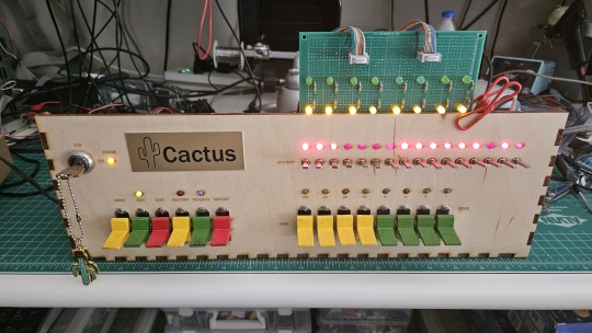
Both the Cactus (the original wooden prototype from years ago) and the new PCB Cactus(es) are essentially derived from a minimal 6502 computer design by Grant Searle for their core logic. Here's what that would look like on a breadboard:
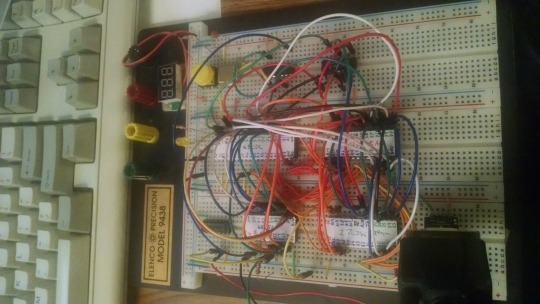
There isn't much to it, it's 32K of RAM, 16K of ROM containing Ohio Scientific's version of Microsoft BASIC, a 6850 ACIA for serial interaction, some logic gates, and of course a 6502 microprocessor (NMOS or CMOS, doesn't matter which). You hook it into a terminal and away you go.
Grant's design in turn can be best described as a distilled, modernized version of the OSI Challenger series of computers. Here's an OSI-400 and a Challenger 4P respectively:
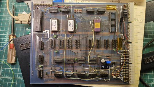

The left one is a replica of the 400 circa 1976, also called the Superboard. It was affordable, endlessly reconfigurable and hackable, but ultimately very limited in capabilities. No BASIC, minimal monitor ROM you talk to over serial, but you could connect it to a bus to augment its features and turn it into a more powerful computer.
Whereas the OSI C4P on the right from about 1979 has more RAM, a video card, keyboard, BASIC built in, serial interface, cassette tape storage, and that's just the standard configuration. There was more room to expand and augment it to your needs inside the chassis (alot changed in 3 years for home computer users).
Grant's minimal 6502 design running OSI BASIC is a good starter project for hobbyists. I learned about the 6502's memory map decoding from his design. I modified and implemented his design on a separate cards that could connect to a larger backplane.
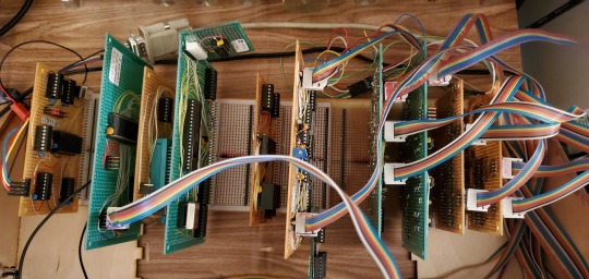
Here are the serial, ROM, RAM, and CPU cards respectively:
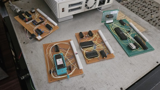
Each one is 100% custom, containing many modifications and fixes as I developed the design. However, that's only half of the computer.
I really wanted a 6502 machine with a front panel. People told me "nobody did that", or couldn't think of examples from the 1970s but that seemed really strange to me. Especially since I had evidence to the contrary in the form of the OSI-300:
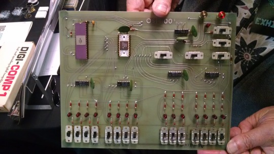
This one I saw at VCF West back in 2018 illustrates just how limited of a design it is. 128 bytes of RAM, no ROM, no serial -- just you, the CPU, and toggle switches and LEDs to learn the CPU. I was inspired the first time I saw one in 2015 at VCF East, which is probably when this whole project got set in motion.
Later that year I bought a kit for a miniature replica OSI-300 made by Christopher Bachman, and learned really quickly how limited the design philosophy for this particular front panel was. It was a major pain in the ass to use (to be clear, that's by OSI's choice, not any fault of Christopher in his implementation)

So... I designed my own. Took awhile, but that's the core of what the Cactus is: my attempt at experiencing the 1970s homebrew scene by building the computer I would have wanted at the time. Over half of the logic in the Cactus is just to run the front panel's state machine, so you can examine and modify the contents of memory without bothering the 6502. I added in all of the things I liked from more advanced front panels I had encountered, and designed it to my liking.
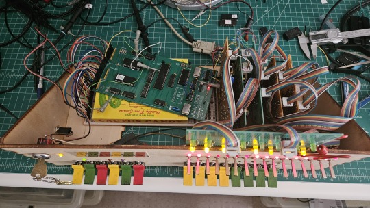
Here's the original front panel, accompanying logic, and backplane connected to the modern single board computer (SBC) version of the machine:
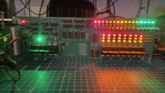
And here's the new Cactus SBC working with the new front panel PCB, which combines the logic, physical switch mountings, and cabling harnesses into a single printed circuit board.
So, what can you do with it? Pretty much the same things I do already with other contemporary 1970s computers: play around in BASIC, fire up the occasional game, and tinker with it.
I've got no permanent storage designed for the Cactus as yet, it's been one of those "eventually" things. The good news is that a variety of software can be ported to the hardware without too much trouble for an experienced hobbyist. A friend of mine wrote a game called ZNEK in 6502 assembly which runs from a terminal:
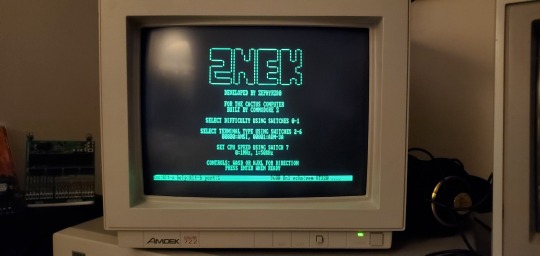
Right now, you have to either toggle in machine programs from the front panel from scratch, burn a custom ROM, or connect it to a serial terminal to gain access to its more advanced features:

Here's it booted into OSI BASIC, but I have also added in a modern descendant of Steve Wozniak's WOZMON software for when I need to do lower level debugging.
I've also got a video card now, based on the OSI-440. I have yet to implement a keyboard, or modify BASIC to use the video board instead of the serial connection. Even if I did, screen resolution is pretty limited at 24x24 characters on screen at once. Still, I'm working on that...
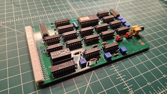

Anyway, I hope that answers your question. Check the tags below to see the whole process stretching back to 2017 if you're curious to learn more of the project's history. I'm also happy to answer any more questions you might have about the project.
267 notes
·
View notes
Text
Hell is terms like ASIC, FPGA, and PPU
I haven't been doing any public updates on this for a bit, but I am still working on this bizarre rabbit hole quest of designing my own (probably) 16-bit game console. The controller is maybe done now, on a design level. Like I have parts for everything sourced and a layout for the internal PCB. I don't have a fully tested working prototype yet because I am in the middle of a huge financial crisis and don't have the cash laying around to send out to have boards printed and start rapidly iterating design on the 3D printed bits (housing the scroll wheel is going to be a little tricky). I should really spend my creative energy focusing on software development for a nice little demo ROM (or like, short term projects to earn money I desperately need) but my brain's kinda stuck in circuitry gear so I'm thinking more about what's going into the actual console itself. This may get techie.
So... in the broadest sense, and I think I've mentioned this before, I want to make this a 16-bit system (which is a term with a pretty murky definition), maybe 32-bit? And since I'm going to all this trouble I want to give my project here a little something extra the consoles from that era didn't have. And at the same time, I'd like to be able to act as a bridge for the sort of weirdos who are currently actively making new games for those systems to start working on this, on a level of "if you would do this on this console with this code, here's how you would do it on mine." This makes for a hell of a lot of research on my end, but trust me, it gets worse!
So let's talk about the main strengths of the 2D game consoles everyone knows and loves. Oh and just now while looking for some visual aids maybe I stumbled across this site, which is actually great as a sort of mid-level overview of all this stuff. Short version though-
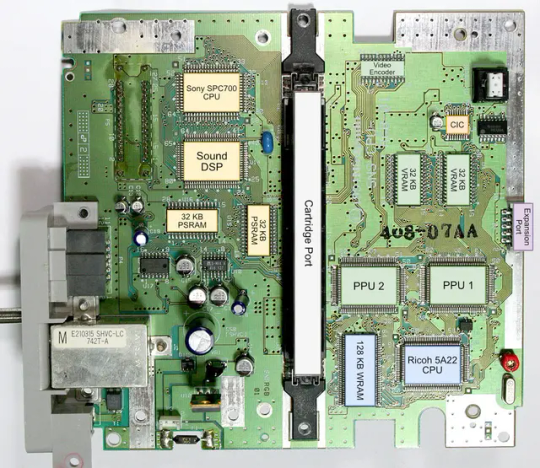
The SNES (or Super Famicom) does what it does by way of a combination of really going all in on direct memory access, and particularly having a dedicated setup for doing so between scanlines, coupled with a bunch of dedicated graphical modes specialized for different use cases, and you know, that you can switch between partway through drawing a screen. And of course the feature everyone knows and loves where you can have one polygon and do all sorts of fun things with it.
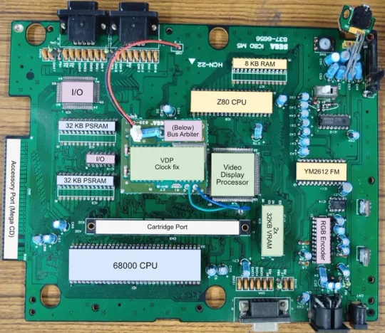
The Genesis (or Megadrive) has an actual proper 16-bit processor instead of this weird upgraded 6502 like the SNES had for a scrapped backwards compatibility plan. It also had this frankly wacky design where they just kinda took the guts out of a Sega Master System and had them off to the side as a segregated system whose only real job is managing the sound chip, one of those good good Yamaha synths with that real distinct sound... oh and they also actually did have a backwards compatibility deal that just kinda used the audio side to emulate an SMS, basically.
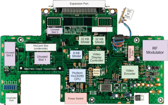
The TurboGrafix-16 (or PC Engine) really just kinda went all-in on making its own custom CPU from scratch which...we'll get to that, and otherwise uh... it had some interesting stuff going on sound wise? I feel like the main thing it had going was getting in on CDs early but I'm not messing with optical drives and they're no longer a really great storage option anyway.
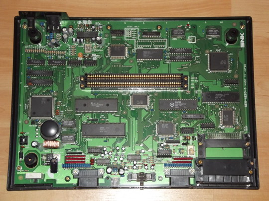
Then there's the Neo Geo... where what's going on under the good is just kind of A LOT. I don't have the same handy analysis ready to go on this one, but my understanding is it didn't really go in for a lot of nice streamlining tricks and just kinda powered through. Like it has no separation of background layers and sprites. It's just all sprites. Shove those raw numbers.
So what's the best of all worlds option here? I'd like to go with one of them nice speedy Motorolla processors. The 68000 the Genesis used is no longer manufactured though. The closest still-in-production equivalent would be the 68SEC000 family. Seems like they go for about $15 a pop, have a full 32-bit bus, low voltage, some support clock speeds like... three times what the Genesis did. It's overkill, but should remove any concerns I have about having a way higher resolution than the systems I'm jumping off from. I can also easily throw in some beefy RAM chips where I need.
I was also planning to just directly replicate the Genesis sound setup, weird as it is, but hit the slight hiccup that the Z80 was JUST discontinued, like a month or two ago. Pretty sure someone already has a clone of it, might use that.
Here's where everything comes to a screeching halt though. While the makers of all these systems were making contracts for custom processors to add a couple extra features in that I should be able to work around by just using newer descendant chips that have that built in, there really just is no off the shelf PPU that I'm aware of. EVERYONE back in the day had some custom ASIC (application-specific integrated circuit) chip made to assemble every frame of video before throwing it at the TV. Especially the SNES, with all its modes changing the logic there and the HDMA getting all up in those mode 7 effects. Which are again, something I definitely want to replicate here.
So one option here is... I design and order my own ASIC chips. I can probably just fit the entire system in one even? This however comes with two big problems. It's pricy. Real pricy. Don't think it's really practical if I'm not ordering in bulk and this is a project I assume has a really niche audience. Also, I mean, if I'm custom ordering a chip, I can't really rationalize having stuff I could cram in there for free sitting outside as separate costly chips, and hell, if it's all gonna be in one package I'm no longer making this an educational electronics kit/console, so I may as well just emulate the whole thing on like a raspberry pi for a tenth of the cost or something.
The other option is... I commit to even more work, and find a way to reverse engineer all the functionality I want out with some big array of custom ROMs and placeholder RAM and just kinda have my own multi-chip homebrew co-processors? Still PROBABLY cheaper than the ASIC solution and I guess not really making more research work for myself. It's just going to make for a bigger/more crowded motherboard or something.
Oh and I'm now looking at a 5V processor and making controllers compatible with a 10V system so I need to double check that all the components in those don't really care that much and maybe adjust things.
And then there's also FPGAs (field programmable gate arrays). Even more expensive than an ASIC, but the advantage is it's sort of a chip emulator and you can reflash it with something else. So if you're specifically in the MiSTer scene, I just host a file somewhere and you make the one you already have pretend to be this system. So... good news for those people but I still need to actually build something here.
So... yeah that's where all this stands right now. I admit I'm in way way over my head, but I should get somewhere eventually?
11 notes
·
View notes
Text

“J K Enterprises” is a reputed Sole Proprietorship (Individual) firm, registered in the year 2015. We are engaged in Manufacturing a diverse range of REFRESH PCB Board, Laptop Charger, Mobile Chargers, USB Chargers, Mobile Adapter, Data Cable etc. These products are manufactured in our high-tech manufacturing unit using supreme grade raw material. With the core values of transparency and uprightness, we are building a collaborative platform for ourselves in the market. Our company is facilitated with all kinds of requisites for qualitative production.
Under the proficient management of our mentor, Mr. JUNAID KHAN, we have earned an unrivaled position in the market and gained massive acceptance of our esteemed customers. Our company is based on the grounds of moral values, principles, and ethics which are led by our mentor.
2 notes
·
View notes
Video
youtube
FPC flexible circuit board production process #fpc #circuitboard #pcb #technology #factory #customer #icgoodfind
2 notes
·
View notes
Text

Multilayer PCBs offer enhanced functionality by incorporating multiple circuit layers into a single board. These versatile boards enable complex electronic designs, compact layouts, and signal integrity. Our multilayer PCBs are meticulously manufactured, meeting industry standards for various applications, including consumer electronics, telecommunications, and aerospace technology.
Visit: https://sqpcb.com/products_category/multilayer-pcb
#Multilayer PCB#customized pcb boards#customize pcb#pcb board#aluminium pcb board#pcb china#printed circuit board#aluminum base pcb#circuit board#custom circuit boards
0 notes
Text
Essential Tips for Efficient Two-Layer PCB Stencil
Please discover essential tips for achieving maximum efficiency with two-layer PCB stencils. From accurate alignment and stencil thickness selection to the right solder paste application techniques, this guide covers everything you need to know for precise, high-quality, two-layer PCB assembly.

#PCB manufacturer#PCB fabrication In india#custom PCB manufacturing in india#prototype PCB manufacturing#low-cost PCB manufacturer#high-quality PCB manufacturing#quick turn PCB fabrication#flex PCB manufacturer#multilayer PCB manufacturer#Best pcb manufacturer#Top 10 pcb manufacturer#Pcb manufacturer near me#Pcb manufacturer in Maharashtra#Pcb manufacturer in haryana#Pcb manufacturer in delhi#Pcb manufacturer in india#Pcb manufacturer in Bombay#Pcb manufacturer in jaipur#Best pcb assemble in hyderabad#Low cost pcb assembled in hyderabad#Good pcb assemble in hyderabad#Free sample pcb assemble in India#pcb stencils#Two layer pcb stencil#Best pcb stencil maker in hyderabad#SMD pcb board assembly in hyderabad#Multi Color Pcb#Sharp Legends
0 notes
Text
PCB Fabrication is the foundational process that transforms raw materials into the physical structure of a Printed Circuit Board. It involves several steps that convert a schematic diagram into a tangible board. This process lays down the framework for the electronic components that will be added later.
0 notes
Text
PCB Manufacturing-PCB Assembly-Hitech Circuits
Hitech Circuits is a lеаding PCB Manufacturing & PCB Assembly company with more than 20 years experience in the electronics manufacturing industry. We focus on PCB Design, PCB Layout, Circuit board fabrication, Turnkey PCB assembly, and electronic parts sourcing services.
With mature supply chain, talented design team, advanced manufacturing techniques and quality control systems, Hitech is able to provide one-stop electronics manufacturing services and solution for our customers to help them stand out in the marketplace.
We offer a full range of Electronic manufacturing services.
-LED PCB
-Heavy Copper PCB
-Multilayer PCB
-HDI PCB
-Flexible PCB
-Rigid-Flex PCB
-High Speed PCB
-High Frequency PCB
-PCB Reverse Engineering
7 notes
·
View notes
Text
The Benefits of Ordering Printed Circuit Boards Online: A Guide to Choosing the Right PCB Manufacturer
In today's rapidly advancing technological landscape, printed circuit boards (PCBs) play a crucial role in various electronic devices, from smartphones to industrial machinery. As demand for these essential components grows, businesses and hobbyists alike seek efficient and cost-effective solutions for obtaining high-quality PCBs. One of the most convenient methods is to order printed circuit boards online. In this article, we will explore the advantages of ordering PCBs online and provide insights into selecting a reputable PCB manufacturer.
Why Order Printed Circuit Boards Online?
Ordering printed circuit boards online offers several benefits, making it an attractive option for many businesses and individuals:
Convenience: The ability to order PCBs from the comfort of your home or office eliminates the need for in-person visits to manufacturers or suppliers. This convenience saves time and effort, allowing you to focus on your projects or business operations.
Wide Range of Options: Online PCB manufacturers offer a variety of options in terms of materials, layer counts, finishes, and more. This flexibility allows you to customize your PCBs according to your specific requirements and budget.
Cost-Effectiveness: Many online PCB manufacturers provide competitive pricing, especially for bulk orders. Additionally, you can easily compare prices and services from different providers, ensuring you get the best value for your money.
Quick Turnaround Times: Online ordering often comes with expedited production and shipping options, allowing you to receive your PCBs faster. This is particularly beneficial for projects with tight deadlines or when you need quick prototypes.
Access to Advanced Technologies: Many online PCB manufacturers offer advanced technologies such as high-frequency PCBs, flexible PCBs, and more. This access to cutting-edge technology ensures your designs are compatible with the latest industry standards.
Choosing the Right PCB Manufacturer
Selecting the right PCB manufacturer is crucial to ensuring the quality and reliability of your printed circuit boards. Here are some key factors to consider when choosing a PCB manufacturer:
Experience and Reputation: Look for a manufacturer with a solid track record and positive reviews from previous customers. Experienced manufacturers are more likely to produce high-quality PCBs and provide reliable service.
Quality Assurance: Ensure the manufacturer follows strict quality control measures, such as ISO certification and regular testing. High-quality PCBs are essential for the proper functioning and longevity of your electronic devices.
Customer Support: Good customer support is vital, especially if you encounter issues during the ordering process or with the final product. Choose a manufacturer that offers responsive and helpful customer service.
Manufacturing Capabilities: Check the manufacturer’s capabilities, including the types of PCBs they can produce, their layer count capacity, and the materials they use. Make sure they can meet your specific design requirements.
Lead Times and Shipping: Consider the manufacturer’s production lead times and shipping options. Quick turnaround times are crucial for meeting project deadlines, so choose a manufacturer that can deliver within your required timeframe.
Pricing and Payment Terms: While cost is an important factor, it should not be the sole consideration. Ensure the manufacturer offers transparent pricing and flexible payment terms that suit your budget.
Conclusion
Ordering printed circuit boards online is a convenient and cost-effective way to obtain high-quality PCBs for your projects. By choosing a reputable PCB manufacturer, you can ensure the reliability and performance of your electronic devices. Whether you are a business looking to streamline your supply chain or a hobbyist working on a personal project, ordering PCBs online provides a seamless and efficient solution.
For those ready to place a printed circuit board order online, consider the factors outlined above to select the right PCB manufacturer for your needs. With the right partner, you can bring your electronic designs to life with precision and quality.
#printed circuit board#pcb manufacturer#pcb supplier#printed circuit board order online#pcb design & manufacturing services#pcb circuit manufacturer in ahmedabad#electronic circuit design company
2 notes
·
View notes