#carbide saw blade
Explore tagged Tumblr posts
Visit Tumblr Blog
Explore Tumblr blogs with no restrictions, modern design and the best experience.
Last Seen Tumblr Blogs


Fun Fact
Kazakhstan’s Minister of Communications and Informatics has blocked the Tumblr site because it contained 60 sites of terrorism, extremism, and pornography in 2015.
Text
“Through the Looking Glass”

Sorry for giving anyone Deja Vu!
To explain...
This comic was actually the FIRST propaganda piece I began drawing for the Finals before deciding to finish the other one instead. I wasn't sure I'd come back to this idea after Mint made their own funny jokes about the mirror-verse situation, but my sister (who gave me the idea for this) wanted to see it finished, so! ✨
Btw, Noir's really close to making a comeback..!! Can his tourney story end a happy one?! Will he escape the constant cycle of trauma?!
@kirbyoctournament
#Noir Fontaine#Mirror Noir#Rope MF#Chain Mofo#Kirby OC Tournament#'Ropes are almost as good as industrial strength tungsten-carbide chain for keeping your counterpart close FOREVER'#Though some brief research told me it isn't even that hard to saw through handcuffs with a hacksaw!#Between the blade/collar and failing to escape his mirror clone I'm just going to say Noir is simply weak to metal! XD#(I guess that's where his half fairy side comes into play?!)#Speaking of chains I hope I got Chain Mofo's colors close?!#There’s still hope Noir Gang! Just a little more...!#While I will definitely be busy through the rest of the month and maybe a few days after cause the Dess Cut is looooong…#…If Noir pulls through I will work hard to whip up (omigosh rope pun?!) some kind of appropriate victory treat...!
50 notes
·
View notes
Text
#CNC spoilboard cutter#cnc insert router tooling#cnc insert v groove bit#cnc helical planing cutter#solid carbide router bit for wood#ball nose solid carbide bit#compression solid carbide bit#upcut solid carbide bit#down cut solid carbide bit#solid carbide router bit for plastics#dowel drill bits#v point drill bits for wood#hinge drill bits#solid carbide dowel bit#solid carbide through point bit#panel saw blade
2 notes
·
View notes
Text
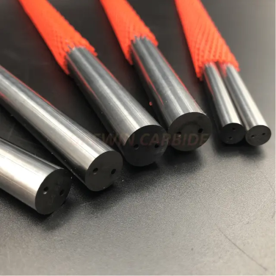
Solid Carbide Rod: The Foundation of Precision Engineering!
Introducing the Solid Carbide Rod, the cornerstone of precision engineering. Crafted from high-quality carbide material, this rod serves as the foundation for a wide range of cutting tools and wear-resistant components. With its exceptional hardness, strength, and heat resistance, the Solid Carbide Rod delivers unparalleled performance in demanding applications. From end mills to drills and reamers, this versatile rod ensures precise machining and extended tool life. The Solid Carbide Rod empowers engineers and manufacturers to push the boundaries of precision, reliability, and efficiency. Embrace the power of the Solid Carbide Rod and elevate your engineering endeavors to new heights.
1 note
·
View note
Text
#diamond saw blade for wood#glue line rip saw blades#hinge drill bits#down cut solid carbide bit#diamond ( PCD ) premil cutters
0 notes
Text
Bimetal and Carbide Band Saw Blade Market to Witness Huge Growth by 2030

The bimetal and carbide band saw blade market refers to the global industry involved in the production, distribution, and sales of band saw blades made from bimetal and carbide materials. Band saw blades are cutting tools used in various industries for cutting and shaping materials such as wood, metal, plastics, and more.
For Sample Report Click Here:-https://www.marketinforeports.com/Market-Reports/Request-Sample/511531
Bimetal band saw blades are composed of two different materials, typically high-speed steel (HSS) teeth welded onto a flexible steel backing. This combination provides the blade with high cutting performance, durability, and resistance to heat and wear. Bimetal blades are commonly used for cutting metal, especially in metalworking and fabrication industries.
On the other hand, carbide band saw blades feature teeth made from tungsten carbide, a hard and durable material that provides excellent cutting performance and extended blade life. These blades are particularly suitable for cutting hard and abrasive materials such as exotic alloys, stainless steel, and other difficult-to-machine metals.
The bimetal and carbide band saw blade market is driven by various factors, including the growth of industries such as manufacturing, construction, automotive, and aerospace. These industries demand efficient and precise cutting tools to meet their production requirements. Bimetal and carbide blades offer superior cutting capabilities compared to conventional blades, leading to increased adoption in industrial applications.
Moreover, advancements in blade manufacturing technologies, such as laser cutting and precision grinding, have improved the overall quality and performance of bimetal and carbide band saw blades. These advancements have further fueled the market growth by enabling the production of blades with higher cutting speeds, improved chip evacuation, and extended blade life.
The market is highly competitive, with several key players operating globally. These companies focus on product development, innovation, and expanding their distribution networks to gain a competitive edge. Additionally, manufacturers often offer a range of blade sizes and configurations to cater to different customer requirements.
Overall, the bimetal and carbide band saw blade market is expected to continue growing due to the increasing demand for efficient cutting tools in various industries. Technological advancements and ongoing product innovations are likely to drive further improvements in blade performance and expand the applications of bimetal and carbide band saw blades in the future.
0 notes
Text
Importance Of Saws While Planning A Vicking Or Adventure Camping
Camping Saw Helps In Cutting Tree Limbs And It Helps You Clear All Obstacles On Your Way. Thus, You Can Keep Travelling Free From Any Worries And It Brings The Best Experience. It’s The Ideal Tool To Cut Firewood And Thus You Will Enjoy Your Trip. A Camping Saw Is Portable And It’s A Necessary Tool To Carry When You Are Arranging A Camping Trip. A Lightweight Camping Saw Is Easy To Carry And It Gives You The Confidence To Go Ahead. There Are Different Types Of Camping Saws And It’s Easy To Choose The One That Fulfills Your Specifications.
Uses Of Carbide Rod Saw
Carbide Rod Saw Is One Of The Best Tools To Cut Ceramics, Plastics, Asbestos, Fibre Glass Etc. It’s Made Of Hard Steel And It Can Cut Any Abrasive Materials. Hence, You Will Learn How Carbide Rod Saw Helps In Handling Heavy Industrial Works. It’s Also Used In Garages And Workshops And The Carbide Rod Saw Has Good Flexibility. Thus, You Will Find It Easy To Use The Saw And It Brings The Beneficial Solutions.
Importance Of Carbide Hacksaw Blade
Tungsten Carbide Hacksaw Blade Features Innovative Designs And It’s Used To Make Thin Cuts In Glass, Plastics. This Carbide Hacksaw Blade Helps In Making Both Straight And Reverse Strokes. So, If You Want To Get Finer Cuts Then The Carbide Hacksaw Can Be The Ideal Saw. The Blades Will Fit Any Standard Hacksaw Frame And You Will Find It Easy To Cut Glass And Other Fine Hard Materials.
How To Use A Coping Saw?
A Coping Saw Is A Type Of Bowing Saw And It’s Used To Cut In Carpentry And Wood Industry. First, You Need To Install The Blades Properly Ad It Helps In Making Easy Cuts. The Blades Easily Release Tension And You Can Adjust The Blades In Your Way. The Saw Features A Handle And It Helps You Compress The Frame To Develop Ample Tension. This Way, You Can Use The Saw And It Helps You Get The Proper Shapes.
Next, You Need To Know About The Coping Saw Blades. The Blades Are 6-12 Inches Long And It Fits Any Standard Frame. It The Best Tool For Precise Sawing Of Wood, Copper Etc. The Blades Feature Smooth Finishes And You Will Feel Confident To Use The Blades. The Coping Saw Blades Help In Using The Coping Saw Easily And It Gives You The Confidence To Manage The Industry Works.
Overall, You Get A Clear Idea Of Why It’s Important To Get Different Types Of Saws While You Are Planning For An Adventure Trip.
#Camping Saw#Carbide Hacksaw Blade#Carbide Rod Saw#Coping Saw#Coping Saw Blades#Craft Saw#Diamond Hacksaw Blade#Diamond Wire Saw Blade#Emergency Saw#Hacksaw Blade Includes Blades
0 notes
Note
is it too weird to ask the textures of everyone, like if I just touched them how would it feel, especially curious about pomni and ragatha hair
Caine's body feels like tungsten carbide metal (excluding the gold parts, which just feels like hardened gold), and his gums and teeth definitely feel like the real thing, even I dread touching him lmfao
Pomni feels like silicone with metal underneath and has synthetic hair, she's the closest to feeling like you're just touching another human. but if you touch her teeth, they feel like sharpened saw blades.
Ragatha would feel like a pillow with a thick hard endoskeleton structure inside, her hair feels like soft yarn.
Jax would feel like silicone with metal underneath too, but when you get to his hands they're hardened gold. The rest of his limbs feels like one of those flexible, lazy phone holders.
Gangle feels like silk sash, her mask is porcelain.
Z feels like an aluminum sheet too with bumps of bolts, especially on the head. Their arms feel like the usual metal, the smaller ones feel like a mannequin's from a department store, their peg leg having a smoothed out wood-like texture to it that won't get you a splinter if you try to caress it.
Kingr feels like a smooth marble texture, his arms feel like folding plastic (you know the squeaky hammer toys? yeah, those ones, but thicker) and the hands themselves feel like the usual metal, although a little rough.
Bubble feels like a cloth, but with a rough, rounded metal sheet underneath said cloth and small bumps of bolts trailing all the way
#thanks for the ask!#tadc#tadc au#harlequin au#tadc harlequin au#the amazing digital circus#pomni#caine#ragatha#jax#gangle#zooble#kinger#hope this helps anon
50 notes
·
View notes
Text
Don't rush,don't be others,just be yourself.May everything you work for have a romantic outcome in the future.

2 notes
·
View notes
Text
T.C.T. CIRCULAR SAW BLADE
Material: Cemented Carbide
Extreme Durable Quality And Long-Lasting Service Life
Effective Noise Deduction Thanks To The Silencing Groove
As Custom T.C.T. CIRCULAR SAW BLADE Suppliers, Lichang is a professional manufacturer majoring in producing drill bits, chisels, hole saws, and other tool accessories.
With a land area of 120,000 ㎡, Lichang has five main workshops and 700 machines. Lichang has always taken the lead in equipment investment and advocates for a safer working environment and the completion of quality systems with new technologies in production.
As China T.C.T. CIRCULAR SAW BLADE Factory, Lichang is a cooperative team consists of more than 400 workers. We respect and care for our employees, clients, and society and provide our employees with regular and professional training. Over the years, we are constantly improving our technology to create better products for clients.
CONTACT US
PHONE: +86-0571-88303751
E-MAIL: [email protected]
ADD: NO. 975, HUANCHENG NORTH ROAD, KANGQIAN STREET, DEQING COUNTY, HUZHOU CITY, ZHEJIANG PROVINCE

0 notes
Text
Filament for 3d printing standard piston engine stuff
Blend nylon, polycarbonate, polyester, weather proof cable (pretty sure it is Polyphenylene sulfide & or thermoplastic polyamide) & trash can polypropylene. Blend in only glass blender that is strong but cheap & has blades that are very sharp but typically like to smash things in the side walls of the blender.
From there is has to be mixed together in another "blender" it's not grinder or blender though. Its a "sand blaster blender" 2 or 3 inputs of a sandblaster full of the ceramic, metal, & the plastics in an argon environment that sucks the polymers together with the metal back in & then accelerates (fires) them into each other at high velocity. Everything must be dry, extremely dry & grounded. Or made to be positively charged in the cone shaped vacuum separator like design. So saw dust vacuum separator will work for this & it's metal. But they can be expensive, it depends on what you want to do & make, me & others.
After rock polishing with large (semi I guess) medium & very small hardened steel ball bearings, make sure I get (or anyone else) micron sized nickel, selenium, zirconium, molybdenum, & silicon
Also these ceramics need to be bought & rock polished. These are all high strength & hardness ceramics that are sucky to deal with. But "polishing" them just means breaking off tiny small chunks to get them fairly uniform & to make them slightly charged. But it must be done at then end because you are, very likely, going to ruin your rock polisher if you didn't electroless boron nitride coat/plate them.
Caswell Inc is a great place to buy the playing kit for boron nitride. They even have an app for your phone.
Boron carbide, zirconia- alumina, silicon carbide. Cubic boron nitride can help as well.
During the "blending stage" (hopefully you played the inside of the cone drum thing otherwise this will absolutely destroy it & wear it away hard) you are going to make sure to go to smaller & smaller sizes of the cone & faster & faster speeds of travel for the plastics, metals, and ceramics. If you started out with a very large vacuum saw dust separator it will be harder from here but you can place smaller ones inside. This means it can act as a cascade onion "blender" all in one. Which is cool!
But most of us can't do that... So instead it's fine to start small & just go with a cut up big plastic trash can then work your way down, for what it is worth.
From here it's melting everything with the right ratios. Depending on what you want your ratios will massively change results. This is for the whole engine block & case & head. Like a small single cylinder 4 stroke that's maybe no more than a 125cc. I recommend just sticking to 75cc to make it easier to print everything.
The plastics are even blend, so that means equal parts & there are 5 total so 20% for each. Nothing fancy there.
The metals are different, so harder sadly. You want mostly nickel, you will never go above 89% for the metal ratios. So to make it easy, 75% is a great starting point. That leaves only 25% left for 2 other metals, 1 metaloid, & a non-metal. Zirconium & molybdenum are annoying, seriously & they tend to be expensive! So this means they have the greatest total out of that 25%! *Sarcastic* yay! You can get away with less in other areas but it's hard to blend that all in one spool & soooo...nah. make multiple but honestly who had the time for all this so it's probably easier to just blend it all together for one run.
Split zirconium as a 15% & molybdenum as a 5% which is a lot. Subtract 20 from 25 & you get 5% left over. Although that's because the ceramics & plastics are going to bond chemically with these metals to make this work together, later. Whole thing.
So 5% left now. Selenium & silicon, silicon is 1.5%, yes a harder number to work with by gram weight, but doable. The rest is selenium. 3.5% of selenium added in by weight.
Next are ceramics. Ceramics are annoying as well, sadly. These bastards have no even numbers! For their ratios to each other at all! So be prepared, just saying. Which we will get to the ratios of metal powder (that is already ratio'd as a total whole weight) & the plastics (that are already ratio'd as a total whole weight) later for the 3 coming together in the final ratio needed. Ceramics first.
3 ceramics or if you want 4, but boron is in 2 & so it has to be changed for that blend as there is already silicon & zirconium in the metal blend. Which makes it tougher to do this. The zirconia-alumina (yes if you Google high strength & hardness ceramics you get these, just so happens they work well together for this application & really I like the coincidence honestly) is a semi-majority. Its 40.3362% by weight.....
Yup.
Its actually super important to go 4 decimals. So large weight is needed to make it easier on everything. Who the hell is measuring nanograms, not me. Or micrograms for that matter. Milligrams are hard too, but actually doable with relatively cheap scales you can buy on Amazon even. But f those other snaller grams. Nope, not doing it.
Boron carbide is 5.0522% and silicon carbide takes up the rest. Which is 100% - 45.3884% & that works out to 54.6116% of silicon carbide.
Now, if you want to use some cubic boron nitride you can put together a ratio like this to start off with instead. Zirconia-alumina is 32.5632% boron carbide & cubic boron nitride works to 25.4363% & the rest is silicon carbide, so 42.0005%.
Which....kinda sucks. But larger weight totals make it much, much! Easier.
Now the ratios of the plastic, metal, & ceramics combined. They are not easy non-decimal numbers. So, doing that again. Plastic is 40.2361% the metals are 26.1212% the rest is ceramics for a 33.6427% by weight.
The majority is still plastics, polymers. Ish. Kinda, not really. Most is metal & ceramics. But it needs to be heated together & squeezed & extruded through a nozzle to make a filament.
So, sandblasters have a tungsten carbide nozzle that you can electroless boron nitride plate. Which works. But diamond would be better, however who had the money. Geez. There are 1.75mm opening coolant holes tungsten carbide rods that you can buy that are straight pass through rods, somewhat expensive but not terrible.
Playing them is also not terrible. It makes it last significantly longer. You must keep a very, very consistent ratio throughout this & it likes to separate easily, which is the worst. So no vibration feeding or auger feeding can be done. There needs to be a cone that feeds to the rodz funnels are great. If you could find one the right size.
So instead this is the best & only way to actually do this, but it's a "suck it up and just do it stop complaining to yourself" way. You need to evenly spread this out with a non-separated ratio of everything & squish it with a lot of heat. Like with a T-shirt logo press. Or with something quite similar to this. One plate is not done. Not above 500c & not below 380c! This will destroy bonds and or not adhere. The pressure is at least 100 psi no more than 500psi. The higher you go the worse performing it gets past a point but depending on how dry it is, if you got ratios right if you had more static that day even to if you mold released or not all of it will change total pressure. Practice, but remember I & we don't need it perfect I have stuff below to help remove this inaccuracy & inconsistency to make sure it is good at the end.
Make several, you aren't perfect so it won't be perfectly blended. Its okay I have a way around that. Get a heated roller. Think making pasta & the rollers are heated. That's what that is. Which means you can get your stainless steel pasta roller & electrically resistively heat it after ceramic coating it to make sure it doesn't zap you & you are good to go! 👍
From here you squeeze the plates to a thinner plate, 3mm if you can do it. 1mm is great too. No more than 5mm because they suck to break and snap apart which is what I & anyone else following along needs to do. Get out a soldering iron, yup. You need a SOLDERING IRON!!!
So after you get that out you will "score" a grove into the new sheet you just created & "break it" apart after letting it cool. DO THIS IN A WELL VENTILATED ROOM & OR OUTSIDE!!!! Please, your lungs will die sooner than you wanted & replacements are hard to find. Make sure to use respirators (air filters strapped to your face) & gloves (nitrile works) & a fume hood with a great air filter for the off gassing that occurs. Activated charcoal (carbon) with a great particle filter filter, meaning two different filters. A percolation setup as a pre-filter stage works too, water is fine as long as it is distilled & deionized. Percolation means your (sticky icky) favorite past time filter. Lol, or just anything that allows for a tube to go underwater & have air sucked through & it bubbles up through it. No worries ☺️.
Now after you make sure you have those, you cut the sheets into strips after breaking them after they cool & or heat cut them. From there you will roll them in a vacuum in the long ways fashion, make sure your strips are wide enough to do this! Then flatten them in the roller in the vacuum.
Amazon doesn't have vacuum boxes big enough! So instead I & you can make a vacuum pump do work for us. A sandblaster cabinet can be modified to have structural corners added with light epoxy & or welding done. I recommend welding with a basic spot welder because you only need a plate steel that is 3-5mm thick at corner angles & arches from those to the longer flat sections.
Think a round box inside the box. This allows for the flat parts of the sheet steel to be supported by the plates & the corners so when it tries to collapse it actually pushes against the pressure & uses stronger material to accomplish this. Bolting them in after drilling them epoxying them down is another great way to get this accomplished if you don't know how to weld. It work just as well too!
After you made your huge vacuum chamber that has little arm holes already in it with the gloves provided that can handle abrasion & heat & all that already, because sandblaster cabinet, remember that pressure is different & wants to work it's way into it.
So, you need to significantly epoxy & or bolt more bolts down on your gloves to seal them & prevent vacuum leaks. The gloves are likely thick enough to not burst if they are halfway decent. If not fiberglass & or kevlar can work as a fabric you place over the gloves to make sure they won't break. You just need to bolt down the fabric to the cabinet where the gloves are bolted in & sealed too.
After you make you vacuum cabinet. Steps above. You can now roll the polymer "rug" strips flat & then fold them & proceed again. Vacuums don't have convection cooling. So flatten & fold. Then on to the next one. Do this to all of them first, which is why I had you read that you can make multiple together at once.
The heat of the roller needs to never be above 500c & below 380c! This is extremely important! It destroys bonds & makes it likely that much of it won't adhere together later. Crumbles suck! Remember the psi problem too.
Keep the vacuum pump vacuum pumping. This gets rid of volatiles & off gassing that can contaminate the polymers & or metals/ceramics.
After you complete all strips to folded (just once in half is fine) semi-sheet/plate things you move on to letting it cool off in argon.
Argon gas, yes.
From here it's so it again with another fold then roll it to very long strips again.
Repeat cooling argon recirculation pump. Pump argon out & compress it into tank. Use compressed argon again, you use vacuum pump for off gassing & volatiles separate, filter them if you can.
Then vacuum pump it, get the strips turned into a nice braid after rolling them thinner & then rolling them sideways long ways to turn them into more fiber while they are still warm. Upon braiding you will roll those all together flat one way then twist that then roll it flat again.
Then from there you need to cool them, so, another cooling stage.
Then vacuum then fold the sheet & roll it & then fold the sheet again & roll it again.
Its done, ish. From here it's needing to be chopped up & it will finally be able to go through extrusion.
Yes. I know. This has been a lot of work... Its worth it though.
From here the chopping up is similar to stripping but all done in the argon cabinet. So it doesn't oxidize, mostly & it remains very cool as argon is a much better thermal conductor than regular air! Yay!
The hot plate you used to squish this would be useful to have in there already. But if not get it. You are going to roll these stupid things into pellets that you can actually use with it, unless you have another method in which case use that. I use a tube roller, it's the rollers but I have a tapered tube on the inside that has grooves in it like a cartoon tunnel drill for villains. Funny, but actually totally usable. I metal 3d printed it using a online website (pcbway, xometry, jlcp, etc etc all work) you don't need it to have grooves I just wanted it to be highly specific in sized & shape at the end.
I also plated it. Nickel (it's stainless steel) plated then nickel boron nitride from Caswell Inc.
You can just get away with a stainless steel funnel you can buy at a store for cooking & it will 100% work! It just needs to have no holes in it. Less argon & a little more heat will do the trick.the pellets come out as little round balls & that's how you know they are done. Personally I recommend no argon in a vacuum so there are no argon pockets of air, but it's okay if they are there in very small quantities & sizes.
If not then you can then vacuum it out & just reheat everything & roll them through again (in the tube) & have it be a slightly smaller size to remove all argon gas pockets & have them come out as little pellets again, woohoo! If you use the plate you just need another plate & you'll rotate the plate around in a circular fashion until you get little pellet balls. Works the same just somewhat more work, you need a separate sheet & or plate for the heated surface below. That's all.
Now from here the sandblaster nozzle & or tungsten carbide rods with a 1.75mm coolant hole will be used. You will need to heat them, typically that means a iron-ceramic (the same in electric stove top coils) heating element & a thermal probe in-between with a little boron nitride thermal paste to tie it all together. This lets you know what you need to know for heat. But! We have to feed pellets into the hole & with need a connector funnel.
Soooo.....
Here's where a lot of things become based on what you want to do & so on. If you have a Dremel (rotary tool) you can use just about any diamond cone shaped but to enlarge one side of the road or sand blaster nozzle. Diamond is harder that tungsten carbide. So it will do it. To fit it a press fit is easiest to do. That means another rod with a 2mm coolant hole is best, but they are massive so you will need to funnel down that other rods (or nozzle) tip that will press fit into that & seal with thermal paste (boron nitride) yes that part is actually necessary. The pressures during extrusion get higher & there is a lot of very small fine particles that will fit through your not perfectly sized holes. Be realistic with yourselves like me & so you will do it good but not perfect...
To feed this in, the pellets, a piston driven heating tube is the only way to do this. Yes, that is right. So an electric motor driving a crank (any piston compressor for ac components will work) is the only way to do this. But you have to rotary tool out the side & 2 stroke it with pellets. You have to drill out, or rotary tool out, the sidewalks near the cylinder (leave 5-10mm of material in-between the cylinder side walls) & place in heating elements (rods that heat up work just fine) but make sure you plate the cylinder side walls with boron nitride to increase the lubricity of the whole thing as well as the piston heads skirts (sides of the puck) with it too. The extrusion has to be at a minimal 35-42 degrees facing downwards to limit oil from the crank getting into the cylinder. I used no oil at all. I just turned it off & let it cool down. I first cleaned the shit out of it with isopropyl alcoholic & degreaser.
I left a thick grease for wheel bearings on the bearing for the crank & piston connection rod. So it would unlikely move into the cylinder.
I do think it will effect the end result of oil gets in. So...I dunno be careful.
Now, I did this all still in the vacuum chamber. Because it was easier than removing everything & I was tired & didn't want to. Soooo... again it might be worth it to just have everything stuff in there & say bah to removing it until it's done.
During the extrusion process the heat for everything is very, EXTREMELY, finely controlled & monitored. The piston is 410c let it warm up everything inside the cylinder, including the plastic, the piston head, & the head that I didn't describe.
Silly me. So the head is modified in a shape that press fits the other rod/nozzle directly into it. Which meant, a hole saw/drill thing & the rotary tool for fine adjustment & sand paper at the end to really make sure. Press fit is a rubber mallet & some cloth because tungsten carbide is extremely hard & can cut through that aluminum like it's not even there. Be careful please. A healthy gasket material on the sides & making sure to fully remove camshaft & making sure the valves remain stuck while also grinding down smooth the valves to be completely as flush as you can to the head is needed, just as much as the inside of the head to taper it to the other rod. The smaller the piston the easier this gets.
Right, back to the temperatures needed. 410c for the piston pump is the best temp to start off with, slow but high torque is best for this.
The next rod/nozzle that is the 2mm coolant hole or sized one is going to be much hotter, 550c the entire way. The heat bleed is crap, so a copper capillary tube is the right call. You just need to drill a hole through the cabinet & seal it with epoxy & run it to a computer radiator & use a computer pump. Works just fine the return line is just a copper tube that goes to the capillary tube at the press fit juncture.
But to make it, likely, much easy on you & I (although I figured quick disconnects with a metal hose clamp would work & so that's the working thing going on moving forward) you could just thermal epoxy & copper tube it up! It works pretty well, as well. You are going to need thermal paste g or epoxy anyways to adhere it to the juncture & transfer heat but still *shrugs* most don't want to solder I get it & this will work from a smaller tube to a larger tube all the same.
From here it's cooling it down only to 485c & keeping that going all the way to where it comes out.
From there a filament holder roll is your best friend. You have to be very careful to not lose heat during the process of rolling it & turning it, so a ir heater works just fine for this. 👍 😁
From here after all pellets are processed & you are fine with the small amount left in the piston pump, you are done. Turn off the ir space heater & let it slowly cool off in the vacuum while you sleep & come back to it after a week because it takes forever for things to cool in a vacuum.
If it's cooled before that, it's okay. But there is a final step to this that has to be done. Anealment. Yeah so in the argon you are going to heat it up to 220c & have it come back down to 15c, roughly, over the course of 3, OMG YES 3 AHHHRRGGGG, days. 3. Days.
After 3 days of waiting & having the temperature slowly cool over that time evenly every 1 hour to make it roughly 15c at the end you are done and your amazingly tough & insanely strong filament is done.
You can print it "normally". The printer needs to have a Tungsten carbide nozzle & that nozzle needs to be boron nitride plated. The heat for extrusion is needed to be around 450c - to 480c.
The plate needs to be 250c but can be just 120c and work but tends to stick a little & sort of sucks.
Higher temps help but I've found not until 250c for my logic sanity checks regarding how this came to be. You'll need to test for your own stuff you, hopefully, make correctly. As per these instructions.
Now from here the 3d printer should be a sealed chamber that you push argon through a small nozzle next to the printer. While it is vacuum pumped out & filtered & cooled before going back in.
Argon is the best way to make this work in a vacuum. You can get away with regular air & standard stuff but it's not really the best way. Sadly. The prints oxidize before the final finish step after printing the piece.
The print should be placed into a little box or something, a bag works, that is also filled with mostly argon (try your best) & then you will heat it up in a oven/kiln.
THIS ISN'T TO REMOVE THE PLASTIC. Its not to get it to that high of a temp. Its to help layer adhesion & to thermal shock it into a freezer.
Or, if you are like me, you heat it up in a oven at 450-550f (broil temp) 232/3c to 287/8c & a pressure cooker filled with dry ice on the bottom is used & then it is sealed after placing the hot print in & slowly venting it out at 5psi until it's fully cooled.
Maintain 5 psi & just let it get to close to dry ice temperature as possible. It doesn't need to be at it, just within 20c. That's it. So calculate thermal mass & time for thermal conductivity for total dry ice to save money. Or, if you are like me, just shove as much as you can in that works & a little more (eyeball methods) & let it cool down making sure to keep venting it. Right, I have a lever on my vent I spent the money for a pressure regulator basically & just needed to drill it out & thread it then screw it on. Works.
I have a thermal proper attached to the print & it's usually inside the thing, if the print allows for it. If not it's best to caution & go for broke for extra cooling time & dry ice. Eyeball method! 😎 Oh yeah!
After that it's let it slowly warm up in the pressure cooker pot & then it's fine-ish to use from them, if you need to immediately.
But, it's best to aneal it with a simple 150c max to room temp over a 8 to 12 (it can be a full day if you just don't want to even look at it until later) hours. I mean this was a lot of work, so eat, drink water, take a shower, do your business, veg out on my content on YouTube, etc etc.
This filament is extreme. Just letting you know. After anealment you can readily use it, but a simple bath of electroless plating of nickel boron nitride for your cylinder, heads, bearings, basically just dunk it in is the easiest way to seal it up & be able to start the honing then cross-hatching process.
Get your bore gauge out & calipers. You need to make sure tolerances are good, everything is squared up, flat, then re-plated.
It will mean a tremendous amount. Don't worry if it doesn't look like it's not 3d printed. You have that where it counts, on the inside 💕 remember 😉.
From here, if you sized it correctly you can use any scooter & or similar single cylinder crank, camshaft, & so on you want.
But you are cool people like me! So! Instead you fully printed all of this, made sure there were holes, dimples, tunnels, & some grooves so you could fully electroform this with nickel & some basic Caswell electroforming/plating with ceramics & metals for infill of those things to increase total strength. Even though the metal, ceramics, & polymers actually should fully ionically bond together after the anealment stage.
Yes that's right, the filament you made ionically bonds metals & ceramics together & does so while also having dendrites & splindles form a network web of inter-weaving lattices that tension to themselves at a molecular & micron/nano scale.
It has to do with the charge values & conductivity during the glass transition phase & plastic phase while the anealment forces excess ions to move out & decay electron orbits into another compounds that needs them. The thermal shock/hardening process set that up to start with but then easing tension off forces a relaxing of the material & moved molecules into a better position for filament dendritic & splindle skin effects to take place. This creates voltage & electromagnetic fields to happen. Which further moves these electrons into a place they need to be using a electron hole & electron redox/ redux (can't remember) flow effect which changes the field effects of the surrounding material due to the electromagnetic z field induced that loops & jumps to other dendrites forming a basic coil. A resonance field effect occurs & changes the properties of the material & it's electrical resistance therein.
This further helps push & pull & bond molecules together to their best state. There are better temperatures & pressures but I know these will work because they are conservative & the effect should occur with them no matter what. But I'm cautious & don't want it to not happen. You can experiment on your own, I'm sure.
To move on, however, this means it's a metamaterial composite that's lighter & stronger than the aluminum & steel you would typically use while being just as thermally conductive as aluminum.
Its even lighter, if done right, than titanium. But that's ratios, leaving areas out that aren't needed, etc etc.
Anyways, that means the crank can be made out of this & made to be plated with a tungsten powder & silicon carbide powder together with a cementing of nickel carbide & boron carbide. The heat shock forces it to bind very well at much lower temperatures than normal.
But you can get away with the tungsten powder, silicon carbide & a little molybdenum & chromium. If you plate like brick & mortar style in the intentional holes & dimples it becomes much stronger & shears into a bind crystalline formation like hardened steel! Cool! Even better is that is doesn't take much by volume, honestly a few grams of each, well ish. If a 75cc engine is assumed then the crank will be needing about 47.865 grams total of everything I talked about with a ratio for the tungsten, silicon carbide, nickel carbide & boron carbide of 7% tungsten 16% silicon carbide 12% nickel carbide 65% boron carbide.
But that's a lot of boron carbide. So. I figured 72% tungsten 8% silicon carbide 11% molybdenum & 9% chromium would be easier because tungsten powder is fairly cheap.
Anyways, nickel forming then boron nitride plating then silicon carbide plating (Caswell kits) then nickel electroforming will work pretty decently well.
Same treatment process for thermal shock & anealment. But it's longer now. The thing has to be thermal shocked & anealed first before electroforming (so it's bonded & strong) but then it has to be done again to make sure it's bond structure goes back & remains strong. Heat & electricity is generated during the electroforming & plating process, which will sever bonds & introduce gaps again. So another round will work to solve that.
After that it's fully done! 👍😁 Completely. You can now make sure tolerances are good, things are bolted together, bearings are there, lube & oil for engine break in is put in, assembly lube used, timing is good, belts are tight, or gears depending on what you do, everything is ready with gaskets (use correct gasket material, like thin aluminum sheet & or steel shim, rtv, etc) & try your best to start her up!
You can print injectors, carbs, heads, valves, crank, camshaft, pumps, compressors, turbos, etc all from this material & it works with extremely high high & tension, pressure & more for even your exhaust. Of course I am talking about after electroforming & plating like I wrote down & you read. It still does without that, but it won't go as far. Its only 20psi max for boost (*sarcastic shrugs* oh well) same for total thickness at play for the cylinder of the engine block. In fill is a big deal & wall thickness too. If you can brick later, do so but remember it's not available for everyone.
Brick layering a 3d print should be a wavy 3d sinusoidal pattern that uses the "wah woo wahhnn woaahh" pattern to have the next layer fit in-between the last. So you do the outside & the inside then fill in the middle to produce the strongest prints. Work with over hangs in the print, if you can, so it will be able to catch correctly. As in the outside wall overhangs into the middle together with the inside, but this time it's such that the middle part for the above layer squeezes out into the outside layers & they can form into that middles overhang. Its like metal inlay. You kind of do a dove tail then press in the metal then sand it down. Well, this is using the heat & the shape of the nozzle to help get it into the area & contract into the overhang & form a 3d mechanical puzzle piece bond with the filament in many areas all over it. Increasing the flex before break (tension) the compression before destruction, & then ability for it to have memory built in, together with a high reduction of occlusions as the heat & filament pushes out the air that could become trapped in-between the print layers.
Boo-yah baby! Oh yeah! *High fives* Alll-rrright! *snaps fingers & finger pistols at you*
This also helps thermal shock hardening to not crack & break the print. But it usually isn't needed, like I said it's not really available to everyone & then on top of it this version above doesn't exist at all you have to program that yourself.
Instead just use a decent in fill & a larger wall thickness that you can electroform later. The crank is similar but should be mostly full in fill.
You are going to have to polish your crank & camshafts. Same with anything else that needs a very smooth surface to work. This is, possibly, the easiest method to delaying your rabbit hole fixation into a hobby that might cost you some money. Its your very own single cylinder 3d printed engine that can handle extreme pressures (the in fill thickness could just be solid to be fair & then it's based on how much filament you made before this) when properly made thick, but then you can liquid cool it & super turbo it with a direct & port injection. Nothing like making a planetary gear set for your camshafts & using a push pull hydraulic ram for your valves to no longer need springs! Together with a gear system for the camshafts that attach to the lobes so you can have a vvt & a type of vvl based upon the gear moving to move the placement of the hydraulic ram it presses on one side then presses up on the exhaust/intake side to allow for a non-payment infringement Lemke transmission valve train setup that gives you your valves as the throttle & it's able to work to high rpm & has not only vvd but vvt as well.
Hey, remember those computer radiators? They still work for this, those electric pumps are still fine for a tiny 75cc hybrid air & liquid cooled engine 😉👍.
Mass production is not easy. So...yup. it can be made to be, but I'll post about it again later.
Please like, comment, & subscribe to my YouTube & my reddit all that. This is the 3d printer recipe for the crazy full 3d printed engine that can actually be fully not electroformed and will work!
0 notes
Text
Carbide Saw Blades for Steel: Cut Through Steel Like a Hot Knife Through Butter!
When it comes to cutting through steel with precision and ease, nothing beats Carbide Saw Blades. These exceptional blades are specifically designed to tackle the toughest steel materials with unmatched efficiency. Crafted with high-quality carbide tips and advanced tooth configurations, they effortlessly slice through steel like a hot knife through butter. Carbide Saw Blades for Steel provide exceptional durability, extended tool life, and clean, accurate cuts every time. Whether you're working in construction, fabrication, or metalworking, equip yourself with Carbide Saw Blades for Steel and experience the ultimate cutting performance that will leave you amazed.

0 notes
Text

The Different Types of Concrete Cutting — Infographic
Concrete cutting is an essential process in construction and renovation projects, ensuring precision and efficiency. This infographic by Hard Cut Concrete Sawing & Drilling provides a detailed overview of the different types of concrete cutting techniques used in the industry.
Types of Concrete Cutting Covered:
✅ Core Drilling – A hollow, cylindrical drill used to create holes through concrete surfaces with diamond or carbide-coated tips. ✅ Wall Sawing – Ideal for cutting vertical concrete structures like walls using high-quality diamond blades for minimal friction. ✅ Floor Sawing – Used for cutting roads, concrete pavements, floors, and slabs with diesel, petrol, and electric floor saws. ✅ Ring Sawing – A hand-held tool for creating precise holes in confined spaces, perfect for small to medium-sized projects. ✅ Wire Sawing – An anti-vibration method that prevents cracks and reduces material wastage during the cutting process.
For more details, visit www.hardcutconcretesawing.com.au.
This infographic is a valuable resource for contractors, engineers, and builders looking to understand the best concrete cutting techniques for their projects.
#concrete cutting sydney#concrete cutting penrith#concrete cutting central coast#concrete cutting campbelltown#concrete cutting wollongong#concrete#building#modern architecture#construction#architectural#brutalist
0 notes