#buzzer module
Text
youtube
#AC voltage measurment#arduino nano#voltage sensor#ZMPT101B#TM1637 4 Digit Seven Segment Display Module#TM1637#buzzer module#arduino IDE#IOT#smart city#smart home#internet of things#Youtube
0 notes
Text
Unveiling the Melodious Marvel: The Buzzer Speaker Module
In the vast realm of electronic components, one unsung hero stands out for its simplicity yet immense utility — the buzzer speaker module. This unassuming device has found its way into countless gadgets, alarms, and interactive projects, adding a touch of auditory magic to our technological landscape.
The Humble Beginnings
The journey of the buzzer speaker module begins with a simple yet ingenious concept. Imagine a tiny device that can transform electrical signals into audible sounds, creating a symphony of beeps, chirps, and melodies. That’s exactly what the buzzer speaker module does. At its core, it’s a small electronic component designed to produce sound when an electric signal is applied.
The Sound Symphony
What makes the buzzer speaker module truly fascinating is its ability to turn mundane electrical impulses into a delightful auditory experience. With a range of frequencies and tones, this electronic marvel can produce everything from attention-grabbing alarms to whimsical tunes. It’s the musical conductor of the electronic orchestra, adding a touch of harmony to the beeps and boops of our gadgets.
Where You’ll Find It
Step into the world of everyday electronics, and you’re likely to encounter the buzzer speaker module more often than you realize. From your morning alarm clock to the electronic doorbell that announces a visitor, these modules are embedded in a variety of devices that make our lives easier and more efficient.
Think about those interactive museum exhibits that captivate visitors with immersive audio experiences or the friendly chirps of a digital thermometer letting you know your pizza is perfectly cooked. It’s the buzzer speaker module that brings these devices to life, engaging our senses in ways that go beyond the visual.
DIY Delight
One of the most exciting aspects of the buzzer speaker module is its popularity among electronics enthusiasts and DIY hobbyists. With a basic understanding of electronics and a creative spark, anyone can incorporate this tiny musical maestro into their projects. Whether it’s a homemade alarm system or a quirky musical instrument, the buzzer speaker module invites experimentation and innovation.
The Future of Sound
As technology advances, the humble buzzer speaker module continues to evolve, becoming more versatile and sophisticated. With improvements in design and functionality, we can expect to see these modules taking on new roles in emerging technologies.
Imagine a future where smart homes communicate with residents through melodic tones, or wearable devices provide feedback through subtle yet distinctive sounds. The buzzer speaker module could play a pivotal role in making our interactions with technology not just efficient but also delightful.
In the vast landscape of electronic components, the buzzer speaker module may seem like a small player, but its impact is anything but insignificant. From waking us up in the morning to alerting us to important events, this unassuming device has become an integral part of our daily lives. As we continue to embrace the possibilities of technology, let’s not forget to appreciate the charm of the buzzer speaker module — a true unsung hero in the symphony of electronic innovation.
0 notes
Text
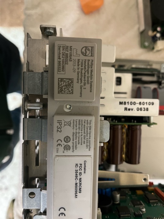
A lot of people really liked seeing the outside of the Philips Intellivue MP5, so let’s take a look on the inside
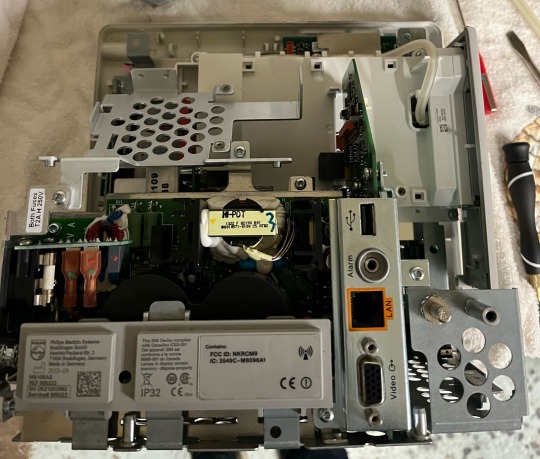
When you take off the back housing this is what you’re greeted with. We can see the power supply, the rear IO board, and the measurement module
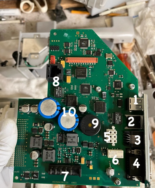
After removing a few more T-10 screws the power supply and the rear IO board slide right out. This is the rear IO board
1: USB port
2: Nurse call relay output
3: RJ45 Ethernet Jack
4: VGA video out
5: board to board interconnect for the power supply
6: Nurse call Relay, the actual Relay component
7: Battery contacts
8: An RJ45 Jack not accessible from the outside, if I had to guess this is either a management port, or it’s a backup port in case the one accessible from the outside breaks but qualified technicians still need Ethernet access to perform maintenance.
9: Piezoelectric buzzer, this will beep is the power supply suddenly gets disconnected and it will continue to beep for quite a while after the power supply is disconnected and even if there’s no battery on board
10: 2 super capacitors. Super capacitors have specs that are somewhere in between a battery and a capacitor. The larger one is rated at 2.2 farad and the smaller one is rated at 1 farad. Farad is the unit of measure for capacitance and it’s named after Michael Faraday. If I had to guess these serve 2 purposes. 1 is to make the power loss buzzer beep and the other is to keep the date and time and any configuration settings stored in volatile memory since there’s no CMOS battery. This is actually pretty smart because batteries die and often leak, but super capacitors don’t leak and corrode and they are ridiculously fast at charging up.
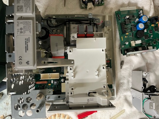
After removing the power supply, recorder driver board, and rear IO board this is what we are left with. The motherboard, the measurement module, the NBP pneumatic pump, and the LCD high voltage backlight board. It uses a fluorescent backlight so it needs a high voltage to make it light up, this can be anywhere from 500 to 1200 volts but they often provide very little current so touching it probably kill you but I still wouldn’t recommend it.
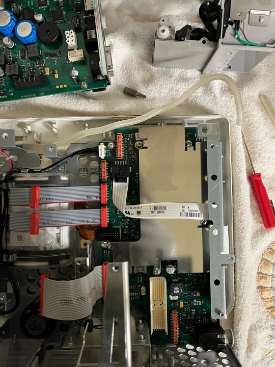
After removing the measurement module were left with just the backlight driver board, the motherboard, and the NBP pneumatic pump. There is a metal shield over the main components of the motherboard for EMI shielding.
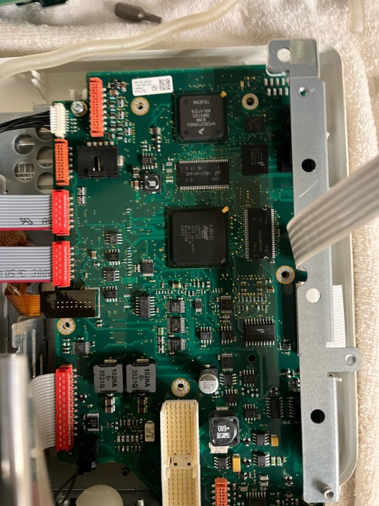
Removing the metal shield grants us access to the CPU (the largest chip on the board) what I assume is a graphics driver chip (the second largest square chip) and 2 EPROMs that are the memory for some software aspects.

Once everything is out we can get a look at everything
1: Battery
2: measurement module side plate
3: measurement module
4: printer
5: Rear IO board
6: printer driver board
7: power supply
8: everything else
The attention to detail is amazing! That one little hole in the plastic just exists to access that screw inside. You can certainly tell that this device was never meant to be a consumer device. It’s built to be taken apart and serviced. All the screws are identical which makes disassembly and reassembly very easy. Unlike consumer products you can definitely tell that there was no expense spared in this things hardware design, that’s due to the fact that they know hospitals are going to pay the 5 figure price of the device because of its extreme quality, attention to detail and very long projected life cycle. Unlike consumer electronics it’s made in Germany and has a ton of hand assembly involved.
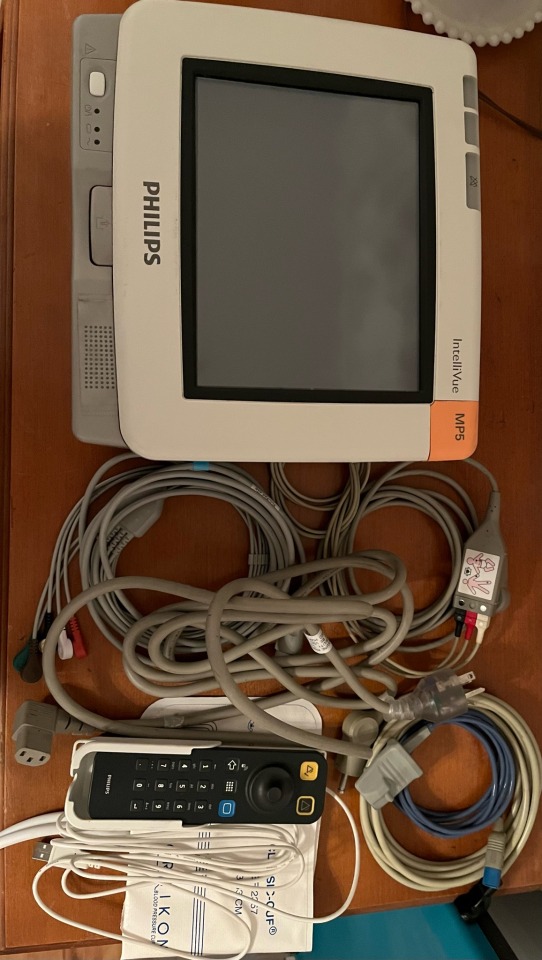
This is everything I have for mine. The monitor itself. 3 lead ECG cable. 5 lead ECG cable. Pulse oximeter. Hospital grade IEC power cable. Blood pressure hose. Adult arm blood pressure cuff. And the Intellivue remote. I got the remote today, idk why but people are selling them for super cheap on eBay. I paid $10 for it brand new in box. They usually go for like $500 from philips directly so I have no idea why people are selling them for so cheap. It does have to be plugged in via USB but it comes with a very long cable.
I finally got around to getting one of my servers to run the Intellivue XDS application. It’s a windows application meant to act as the server for Intellivue monitors. It also has a remote monitor function so you can view what’s on the monitor on the server, but it doesn’t work with the software version my monitor has. It can also log data but I spent 4 hours trying to setup the windows server needed to get that to work and just couldn’t get it to work. It’s probably due to the fact that the documentation on it is absolutely terrible.
4 notes
·
View notes
Note
hey flans, what's that pedal you've started using on Minimum Wage, that makes like a door buzzer sound? that thing is INTENSE
It's actually the old Line 6 FM4 (it's the big old-style pedal-this is the purple one) It has modulation effects and synth/filter effects. It actually has a very warm MuTron-like auto-wah (a lesser loved sound except for Deadheads) that I am currently using on Particle Man. (Kinda subtle) But it can also do some EXTREME fuzz-filtering. Years back I played Older on it and it was pretty nuts-it was a favorite sound for me.
But it had so much dust and filth coffee and water poured into it, and half the plastic parts had broken off so I couldn't adjust it or use the batteries since the lid fell off-it just was trashed. I just took it off my board to clean it up and then never got back to it. Finally over covid got another new-old-stock one and started setting it up. Takes a while to dial in because it's very volume sensitive (and I play much harder in front of people than when there aren't people-and that fact took me a couple of decades to figure out!)
They have updated that line recently (! damn-bad timing) and it's smaller but seems to have all the crazy sounds... I moved too soon!
youtube
28 notes
·
View notes
Text
Arduino-Compatible Boards: Mega 2560 Pro, LilyPad, and Nano
Arduino is a popular open-source hardware and software platform that is widely used for building a variety of electronic projects. The platform has a vast range of boards that are compatible with it, each with different features, capabilities, and price points. In this blog post, we will discuss three of the most popular Arduino-compatible boards: Mega 2560 Pro, LilyPad ATmega328P, and Nano Board R3.
Mega 2560 Pro:
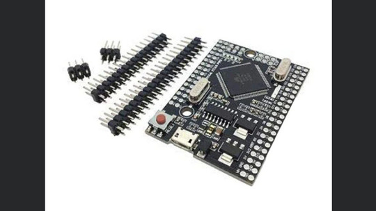
The Mega 2560 Pro is a powerful and versatile board that is designed for advanced projects. It has 54 digital I/O pins, 16 analog inputs, and 4 UARTs (hardware serial ports). It also has a USB host port that can be used to connect USB devices such as keyboards, mice, and game controllers. The board runs on the Atmel ATmega2560 microcontroller, which has a clock speed of 16 MHz. This makes it suitable for running complex programs and driving multiple sensors and actuators simultaneously.
LilyPad ATmega328P:
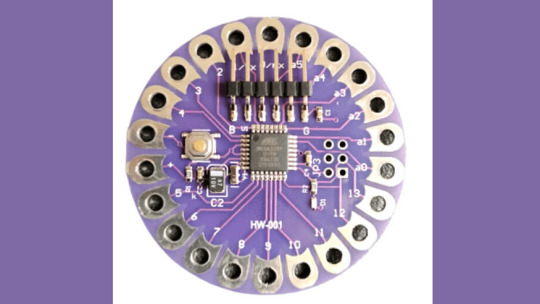
The LilyPad ATmega328P is a wearable board that is designed to be sewn onto clothing and other fabric surfaces. It is based on the Arduino platform and uses the same Atmel ATmega328P microcontroller as the Arduino Uno. The board has 14 digital I/O pins, 6 analog inputs, and can be powered by a 3.7V LiPo battery. It also has a built-in USB port for programming and debugging. The board is compatible with various LilyPad accessories, including sensors, LEDs, and buzzers.
Nano Board R3:

The Nano Board R3 is a compact and affordable board that is ideal for beginners and small projects. It has 22 digital I/O pins, 8 analog inputs, and can be powered via a USB cable or an external power source. The board runs on the Atmel ATmega328 microcontroller, which has a clock speed of 16 MHz. The Nano Board R3 has a built-in USB port for programming and debugging and is compatible with a range of shields and modules that can be used to expand its capabilities.
In conclusion, these three boards offer different features and capabilities, making them suitable for a wide range of applications. The Mega 2560 Pro is ideal for complex projects that require many I/O pins and high processing power. The LilyPad ATmega328P is perfect for wearable projects, while the Nano Board R3 is an excellent choice for beginners and small projects. Regardless of which board you choose, you can be sure that it will be compatible with the vast Arduino community and its extensive library of code and examples.
2 notes
·
View notes
Text
Esplora Arduino game controller

The ESPLORA Arduino game controller Board is an Arduino-compatible microcontroller board based on the Arduino Leonardo. Unlike previous models, it comes equipped with a variety of built-in sensors for immediate use in interactions.
This guide is perfect for individuals interested in using Arduino, but who don’t want to dive into electronics right away. To learn how to use the ESPLORA Arduino game controller Board in a simple and clear manner, be sure to read the Getting Started with Esplora guide.
The ESPLORA Arduino game controller Board boasts onboard sound and light outputs, as well as multiple input sensors such as a joystick, slider, temperature sensor, accelerometer, microphone, and light sensor. Additionally, it offers the option to enhance its functions through two Tinker-kit input and output connectors and a socket for a color TFT LCD screen.
Similar to the Leonardo board, the ESPLORA Arduino game controller Board also utilizes an Atmega32U4 AVR microcontroller with a 16 MHz crystal oscillator. It features a micro USB connection that can function as a USB client device, such as a mouse or keyboard. Additionally, there is a reset push button located in the upper left corner of the board for restarting purposes.
There exist four indicators, each displaying a different status.
The green indicator shows if the board is currently being powered.
The L [yellow] connects directly to pin 13 on the micro-controller for easy accessibility.
The [yellow] LED indicates data being transmitted or received through the USB connection.
Within the board lies all the necessary components to support the microcontroller. To begin, just connect it to a computer using a USB cable. The ESPLORA Arduino game controller Board is also equipped with built-in USB communication, allowing it to function as a mouse or keyboard when connected to a computer. It also offers a virtual serial/COM port (CDC). This alters the behavior of the board, which is further explained on our getting started page. On this page, you can find all the instructions for configuring your board and utilizing the Arduino Software (IDE) for coding and electronics experimentation.
The transfer of data, both in and out.
The ESPLORA Arduino game controller Board features a classic gamepad design, including an analog joystick on the left and four push buttons on the right. It also comes equipped with several onboard inputs and outputs:
The analog joystick features a center push-button and two axes, designated as X and Y. There is also a central pushbutton for added functionality.
Arranged in a diamond formation are 4 push-buttons.
The slider for the linear potentiometer is located towards the bottom of the board.
A tool to capture the volume (amplitude) of the surrounding environment.
A sensor that detects light to measure brightness.
The temperature sensor measures the surrounding temperature.
A three-axis accelerometer detects the orientation of the board with respect to gravity, along the X, Y, and Z axes.
The buzzer has the ability to generate square-wave tones.
The RGB LED features Red, Green, and Blue elements that allow for color mixing and a bright display.
The TinkerKit Inputs allow for easy connection between the sensor modules and 3-pin connectors.
The TinkerKit Outputs allow for easy connection of the TinkerKit actuator modules via the 3-pin connectors.
The TFT display connector can be used for a color LCD screen, SD card, or any other devices utilizing the SPI protocol.
To fully utilize all available sensors, the board employs an analog multiplexer. This way, multiple input channels (excluding the 3-axis accelerometer) can share a single analog input of the microcontroller. Selecting which channel to read is done through four additional pins on the microcontroller.
Communication is essential in any relationship, whether it be personal or professional. It plays a crucial role in maintaining strong connections and fostering understanding between individuals. Effective communication allows for open and honest dialogue, facilitating problem-solving and building trust. Without good communication, misunderstandings can occur, leading to conflicts and strained relationships. Therefore, it is important to prioritize effective communication in every aspect of our lives.
The ESPLORA Arduino game controller Board for the Leonardo offers various features for connecting with a computer, another Arduino, or different micro-controllers. The ATmega32U4 enables serial (CDC) communication through USB and is recognized as a virtual com port on the computer. It also functions as a full speed USB 2.0 device and can be used with standard USB COM drivers. A .inf file is needed for Windows.
The Arduino software comes equipped with a serial monitor for easy transmission of text data to and from the board. Whenever data is being sent via the USB connection to the computer, the RX and TX LEDs will light up on the board. Additionally, the ATmega32U4 has SPI capability accessible through the SPI library. In addition, the Esplora can act as a standard keyboard and mouse, allowing you to use programming to manage these input devices via the Keyboard and Mouse libraries.
The act of creating computer software, also known as programming, involves writing code using various languages and tools. This process requires a combination of problem-solving skills, critical thinking and creativity. Programmers must constantly learn new techniques and adapt to ever-changing technology in order to produce high-quality programs.
To start using the Esplora with your Arduino software (download), simply choose “Esplora” from the Tools > Board menu. For more information, refer to the getting started page. The ATmega32U4 on the Esplora comes pre-loaded with a boot-loader, enabling you to upload new code without an external hardware programmer.
The AVR109 protocol is the chosen method of communication. To avoid using the bootloader, you can program the microcontroller through the ICSP header. Additional instructions are available for reference.
A dedicated library for the Esplora simplifies writing sketches, with methods available for reading sensors and controlling onboard outputs. These high-level methods also perform pre-processing of data, such as converting temperature readings to degrees Fahrenheit or Celsius. Additionally, the library allows easy access to outputs like the RGB LED. For further information and examples, please refer to the Esplora library reference page.
The automatic reset and bootloader activation are key components in the software’s functioning.
Rather than relying on the physical reset button, the Esplora utilizes a software-based reset triggered by opening and then closing the virtual serial/COM port (CDC) at 1200 baud. This initiates a processor reset, temporarily cutting off the USB connection to the computer and causing the virtual port to disappear. The boot-loader remains active for approximately 8 seconds before it can also be activated by pressing the reset button on the Esplora.
Please be aware that upon initial power up, the board will launch the user sketch instead of the boot-loader, if available. Due to the specific reset process of the Esplora, it is most effective to allow the Arduino software to attempt a reset before uploading, especially if you typically press the reset button before uploading on other boards. However, in the event that the software is unable to reset the board, you can manually initiate the boot-loader by pressing the reset button on the board.
The USB port is equipped with overcurrent protection to prevent any potential damage.
The ESPLORA Arduino game controller Board comes equipped with a re-settable poly-fuse to safeguard your computer’s USB ports against shorts and over-current. While most computers have built-in protection, the fuse adds an additional level of security. In the case of a short or overload exceeding 500 mA, the fuse will disconnect the connection until the issue is resolved.
Regarding the appearance of this object, its external features will be discussed.
The ESPLORA Arduino game controller Board PCB has a maximum size of 6.5 inches in length and 2.4 inches in width. The USB and TinkerKit connectors extend beyond the width dimension. Additionally, there are four screw holes that allow for attachment to a surface or case.
1 note
·
View note
Text
Regentropfen-Jagd: Ein einfaches Arduino-Spiel
Wie du das kleine Spiel "Fange den Regentropfen" am Arduino UNO R4 WiFi programmierst, zeige ich dir hier in diesem neuen Beitrag. Die Idee zu dem Spiel kommt von einem Makerspace, welche dieses für den Calliope Mini umgesetzt haben.
https://youtu.be/2SOcPtQ0PkY
Um das Spiel aufzubauen, brauchst du neben dem Arduino UNO R4 WiFi noch zwei Taster. Falls du das Arduino Plug and Make Kit besitzt, kannst du das Spiel auch damit umsetzen. Ich werde dir beide Optionen vorstellen, damit du das Projekt unabhängig davon, ob du das Kit hast oder nicht, nachbauen kannst.


Benötigte Ressourcen für dieses Projekt
Das kleine Projekt am Arduino benötigt nicht viele Bauteile:
- einen Arduino UNO R4 WiFi,
- ein USB-Typ-C Datenkabel,
- ein Modulino Buttonshield,
- ein Modulino Buzzer,
- ein Qwiic Kabel

Bauteile - "Fang den Regentropfen" am Arduino Plug and Make Kit
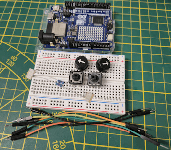
Alternativ kannst du das kleine Spiel auch mit zwei Taster aufbauen und programmieren, dann benötigst du:
- zwei Taster*,
- zwei 10 kOhm Widerstände*,
- ein Piezo Buzzer*,
- diverse Breadboardkabel*,
- ein 400 Pin Breadboard*
Hinweis von mir: Die mit einem Sternchen (*) markierten Links sind Affiliate-Links. Wenn du über diese Links einkaufst, erhalte ich eine kleine Provision, die dazu beiträgt, diesen Blog zu unterstützen. Der Preis für dich bleibt dabei unverändert. Vielen Dank für deine Unterstützung!
Aufbau der kleinen Schaltung mit dem Arduino Plug and Make Kit
Der leichteste Weg, das Spiel aufzubauen, gelingt mit dem Arduino Plug and Make Kit, da es bereits alle benötigten Komponenten enthält. Zwar ist das Kit nicht ganz billig, aber es bietet die Möglichkeit, viele weitere Projekte und Spiele zu realisieren. Aus meiner Sicht lohnt sich die Investition daher definitiv.
Für dieses kleine Spiel müssen wir lediglich das Button Modulino Shield mit einem Qwiic Kabel mit dem Mikrocontroller verbinden. Mit den Schrauben wird das kleine Modul auf der Modulino Base geschraubt und somit sind wir auch schon fertig mit dem Aufbau.


Das Qwiic Kabel hat eine bestimmte Form, sodass dieses nur in eine bestimmte Richtung in die Buchse gesteckt werden kann, sollte es also etwas schwierig gehen, so prüfe dieses zunächst.
Programmieren des Spieles in der Arduino IDE
Für das Programmieren des Spieles verwende ich wie in den Beiträgen zuvor die Arduino IDE. Hier musst du so weit noch nicht geschehen, den Boardtreiber für den UNO R4 und die Bibliothek für die Modulinos installieren.


Für die LED Matrix benötigen wir noch zusätzlich eine Bibliothek, welche ebenso über den Bibliotheksverwalter samt Abhängigkeiten installieren.
Das kleine, fertige Spiel kannst du dir nachfolgend als ZIP-Datei herunterladen.
Spiel - "Fang den Regentropfen" mit dem Arduino Plug and Make KitHerunterladen
//Bibliothek zum steuern der LED Matrix
#include "Arduino_LED_Matrix.h"
//Bibliothek zum Kommunizieren mit den Modulinos
#include
//einbinden der externen Datei animation.h
//diese Datei enthält die Smileys für die
//LED Matrix
#include "animation.h"
//Mehrdimensionales Array welches die LED Matrix
//wiederspiegelt.
uint8_t grid = {
{ 0, 0, 0, 0, 0, 0, 0, 0, 0, 0, 0, 0 },
{ 0, 0, 0, 0, 0, 0, 0, 0, 0, 0, 0, 0 },
{ 0, 0, 0, 0, 0, 0, 0, 0, 0, 0, 0, 0 },
{ 0, 0, 0, 0, 0, 0, 0, 0, 0, 0, 0, 0 },
{ 0, 0, 0, 0, 0, 0, 0, 0, 0, 0, 0, 0 },
{ 0, 0, 0, 0, 0, 0, 0, 0, 0, 0, 0, 0 },
{ 0, 0, 0, 0, 0, 0, 0, 0, 0, 0, 0, 0 },
{ 0, 0, 0, 0, 0, 0, 0, 0, 0, 0, 0, 0 },
};
//Objektinstanzen
ArduinoLEDMatrix matrix;
ModulinoButtons buttons;
ModulinoBuzzer buzzer;
//Index der Tasten A & C
const int BUTTON_A = 0;
const int BUTTON_C = 2;
//Felder zum speichern der Koordinaten
//eines Regentropfen
int raindropXPos = 0;
int raindropYPos = 0;
//Felder zum speichern der Koordinaten
//der Leiste zum fangen des Regentropfen
//die XPos ist fest und könnte ebenso als
//Konstante gesetzt werden
int barXPos = 7;
int barYPos = 6;
//Geschwindigkeit der Regentropfen
//bzw. Pause zwischen den Wechsel der LEDs
const int DEFAULT_SPEED = 400;
int speed = DEFAULT_SPEED;
//Frequenzen für die Töne
const int FREQ_TICK = 400;
const int FREQ_BAR_MOVE = 200;
//Feld zum speichern der letzten Ausführung
//des Wechsels der LED
long lastAction = -1;
//Die Funktion setup wird beim starten und neustarten ausgeführt.
void setup() {
//beginn mit der Kommunikation mit der LED Matrix
matrix.begin();
//beginn der Kommunikation mit den Modulinos
Modulino.begin();
buzzer.begin();
buttons.begin();
//die kleinen SMD LEDs an den Tastern A & C
//aktivieren
buttons.setLeds(true, false, true);
//eine Zufallszahl generieren und dem Feld zuweisen
raindropYPos = generateRandomNumber();
//aktivieren der Leiste zum fangen des Regentropfens
grid = 1;
}
//Funktion zum bewegen eines Regentropfens
void moveRaindrop() {
//am Buzzer einen Ton für 75ms. ausgeben
buzzer.tone(FREQ_TICK, 75);
//Wenn die X-Koordinate größer 0 ist dann den
//letzten tropfen löschen
if (raindropXPos > 0) {
grid = 0;
}
//aktivieren der LED an der neuen Koordinate
grid = 1;
//absenden des Arrays und anzeigen der LEDs
matrix.renderBitmap(grid, 8, 12);
//Wenn die X-Koordinate gleich sieben ist,
//dann ist die Runde zuende
if (raindropXPos == 7) {
//prüfen ob die Y-Position der Leiste mit
//der Y-Position des Regentropfens übereinstimmt
if (raindropYPos == barYPos) {
//anzeigen eines glücklichen Smileys
matrix.loadFrame(happy);
//Geschwindigkeit erhöhen
speed -= 25;
} else {
//Wenn die Koordinaten nicht übereinstimmen, dann...
//anzeigen eines traurigen Smileys
matrix.loadFrame(sad);
//zurücksetzen der Geschwindigkeit
speed = DEFAULT_SPEED;
}
//eine Pause von 600ms.
delay(600);
//Zurücksetzen der Felder
grid = 0;
grid = 1;
raindropXPos = 0;
//erzeugen einer neuen Zufallszahl
raindropYPos = generateRandomNumber();
//anzeigen der LEDs
matrix.renderBitmap(grid, 8, 12);
}
}
//Funktion zum erzeugen einer Zufallszahl
//zwischen 0 und 7
int generateRandomNumber() {
randomSeed(analogRead(0));
return random(8);
}
//Die Funktion loop wird dauerhaft ausgeführt, bis
//der Mikrocontroller keine Strom mehr hat, oder
//auf einen Fehler trifft.
void loop() {
//auslesen der vergangenen Millisekunden seit dem Starten
//des Mikrocontrollers
long currentMillis = millis();
//prüfen ob eine Ausführung erfolgen soll
if (currentMillis > (lastAction + speed)) {
//speichern des Zeitpunkts der neuen Ausführung
lastAction = currentMillis;
//die X-Koordinate des Regentropfens um eins erhöhen
raindropXPos += 1;
//Funktion zum bewegen des Regentropfens ausführen
moveRaindrop();
}
//Aktualisieren des Buttons Objektes
if (buttons.update()) {
//Feld zum speichern ob eine Taste betätigt wurde
bool btnPress = false;
//Wenn der Taster A gedrückt wurde, dann...
if (buttons.isPressed(BUTTON_A)) {
//die letzt Koordinate löschen / zurücksetzen
grid = 0;
//Wenn die Y-Position größer 0 ist, dann..
if (barYPos > 0) {
//den Wert um eins verringern
barYPos -= 1;
}
//Feld auf Wahr / True setzen
btnPress = true;
} else if (buttons.isPressed(BUTTON_C)) {
//Wenn der Taster C gedrückt wurde, dann...
//die letzt Koordinate löschen / zurücksetzen
grid = 0;
//Wenn die Y-Position kleiner als 11 ist, dann...
if (barYPos < 11) {
//die Y-Position um eins erhöhen
barYPos += 1;
}
//Feld auf Wahr / True setzen
btnPress = true;
}
//Wenn ein Taster betätigt wurde, dann...
if (btnPress) {
//ausgeben eines Tones wenn die Taste betätigt wurde
buzzer.tone(FREQ_BAR_MOVE, 75);
//aktivieren der neuen Position im Array
grid = 1;
//absenden der Daten und anzeigen der LEDs
matrix.renderBitmap(grid, 8, 12);
}
}
}
Die beiden Smileys habe ich in die Datei animations.h ausgelagert, dieses wirkt lediglich das der eigentliche Quellcode nicht unnötig länger wird.
const uint32_t happy = {
0x31831,
0x80000404,
0x42081f0,
66
};
const uint32_t sad = {
0x31831,
0x80000001,
0xf0208404,
66
};
Alternativer Aufbau & Programmierung mit Taster am Arduino
Wenn du das Arduino Plug and Make Kit nicht hast, aber trotzdem das kleine Spiel nachbauen möchtest, dann zeige ich dir hier nun den Aufbau und die Programmierung mit einfachen Komponenten.
Aufbau der Schaltung
Die Schaltung am Arduino UNO R4 WiFi ist mit den beiden Tastern auch recht schnell erledigt. Du kannst diese entweder mit einem PullUp oder PullDown Widerstand anschließen, oder du lässt diesen ganz weg und schaltest den Taster via Code über den internen 10kOhm Widerstand von der MCU.

Schaltung - Arduino mit Taster & Buzzer
Der Piezo Buzzer muss an einen PWM Pin des Arduinos angeschlossen werden, diese sind am Board mit einer kleinen Welle / Tilde gekennzeichnet.
Prüfen der Schaltung mit einem kleinen Programm
Bevor wir in die Programmierung einsteigen, sollten wir prüfen, ob die Schaltung funktioniert und wir die Signale der Taster erfolgreich auswerten können. Dazu schreiben wir ein kleines Programm, welches die Status der Taster prüft und wenn einer betätigt ist, dieses auf der seriellen Schnittstelle ausgibt.
//Taster Links am digitalen Pin D3 angeschlossen
#define buttonLeft 3
//Taster Rechts am digitalen Pin D2 angeschlossen
#define buttonRight 2
//Buzzer am digitalen PWM Pin D5 angeschlossen
#define buzzer 5
void setup() {
//beginn der seriellen Kommunikation mit 9600 baud
Serial.begin(9600);
//definieren das die Pins der Taster als Eingang dienen
pinMode(buttonLeft, INPUT);
pinMode(buttonRight, INPUT);
//definieren das der Pin des Buzzers als Ausgang dient
pinMode(buzzer, OUTPUT);
}
void loop() {
//Wenn einer der Taster betätigt wird, dann
//ist das Signal am digitalen Pin auf HIGH.
//Wenn der Linke Taster betätigt wird, dann...
if (digitalRead(buttonLeft) == HIGH) {
Serial.println("Taster Links betätigt!");
//ausgeben eines hellen Tones für 100ms.
tone(buzzer, 600, 100);
} else if (digitalRead(buttonRight) == HIGH) {
//Wenn der Rechte Taster betätigt wird, dann...
Serial.println("Taster Rechts betätigt!");
//ausgeben eines tiefen Tones für 100ms.
tone(buzzer, 300, 100);
}
}
Im seriellen Monitor der Arduino IDE siehst du, dass mehrere Signale verarbeitet werden, obwohl wir nur einmal auf den Taster gedrückt haben, dieses nennt man prellen und kann recht einfach unterbunden werden.
Wie man einen Taster am Arduino entprellt habe ich dir im Beitrag Arduino Lektion 87: Taster entprellen ausführlich erläutert.
Programmieren in der Arduino IDE
Für die Programmierung in der Arduino IDE benötigen wir neben dem Boardtreiber für den UNO R4 WiFi und Bibliothek für die LED Matrix noch Bounce2. Über Bounce2 können wir recht einfach die verbundenen Taster entprellen.

Wie man einen Taster entprellt habe ich dir bereits im Beitrag Arduino Lektion 87: Taster entprellen ausführlich erläutert.
Nachfolgend der Link zum Download des fertiges Programmes als ZIP-Datei.
Programm - Arduino UNO R4 WiFi - Fang den RegentropfenHerunterladen
//Bibliothek zum steuern der LED Matrix
#include "Arduino_LED_Matrix.h"
//Bibliothek zum entprellen eines Tasters
#include
//einbinden der externen Datei animation.h
//diese Datei enthält die Smileys für die
//LED Matrix
#include "animation.h"
//Taster Links am digitalen Pin D3 angeschlossen
#define buttonLeftPin 3
//Taster Rechts am digitalen Pin D2 angeschlossen
#define buttonRightPin 2
//Buzzer am digitalen PWM Pin D5 angeschlossen
#define buzzer 5
//Mehrdimensionales Array welches die LED Matrix
//wiederspiegelt.
uint8_t grid = {
{ 0, 0, 0, 0, 0, 0, 0, 0, 0, 0, 0, 0 },
{ 0, 0, 0, 0, 0, 0, 0, 0, 0, 0, 0, 0 },
{ 0, 0, 0, 0, 0, 0, 0, 0, 0, 0, 0, 0 },
{ 0, 0, 0, 0, 0, 0, 0, 0, 0, 0, 0, 0 },
{ 0, 0, 0, 0, 0, 0, 0, 0, 0, 0, 0, 0 },
{ 0, 0, 0, 0, 0, 0, 0, 0, 0, 0, 0, 0 },
{ 0, 0, 0, 0, 0, 0, 0, 0, 0, 0, 0, 0 },
{ 0, 0, 0, 0, 0, 0, 0, 0, 0, 0, 0, 0 },
};
//Objektinstanz erstellen
ArduinoLEDMatrix matrix;
Bounce btnLeft = Bounce();
Bounce btnRight = Bounce();
//Index der Tasten A & C
const int BUTTON_A = 0;
const int BUTTON_C = 2;
//Felder zum speichern der Koordinaten
//eines Regentropfen
int raindropXPos = 0;
int raindropYPos = 0;
//Felder zum speichern der Koordinaten
//der Leiste zum fangen des Regentropfen
//die XPos ist fest und könnte ebenso als
//Konstante gesetzt werden
int barXPos = 7;
int barYPos = 6;
//Geschwindigkeit der Regentropfen
//bzw. Pause zwischen den Wechsel der LEDs
const int DEFAULT_SPEED = 400;
int speed = DEFAULT_SPEED;
//Frequenzen für die Töne
const int FREQ_TICK = 400;
const int FREQ_BAR_MOVE = 200;
//Feld zum speichern der letzten Ausführung
//des Wechsels der LED
long lastAction = -1;
//Die Funktion setup wird beim starten und neustarten ausgeführt.
void setup() {
//beginn mit der Kommunikation mit der LED Matrix
matrix.begin();
//definieren das die Pins der Taster als Eingang dienen
//und verbinden mit den Tasterobjekten
btnLeft.attach(buttonLeftPin, INPUT);
//Interval zum entprellen auf 5ms. setzen
btnLeft.interval(5);
btnRight.attach(buttonRightPin, INPUT);
btnRight.interval(5);
//definieren das der Pin des Buzzers als Ausgang dient
pinMode(buzzer, OUTPUT);
//eine Zufallszahl generieren und dem Feld zuweisen
raindropYPos = generateRandomNumber();
//aktivieren der Leiste zum fangen des Regentropfens
grid = 1;
}
//Funktion zum bewegen eines Regentropfens
void moveRaindrop() {
//am Buzzer einen Ton für 75ms. ausgeben
tone(buzzer, FREQ_TICK, 75);
//Wenn die X-Koordinate größer 0 ist dann den
//letzten tropfen löschen
if (raindropXPos > 0) {
grid = 0;
}
//aktivieren der LED an der neuen Koordinate
grid = 1;
//absenden des Arrays und anzeigen der LEDs
matrix.renderBitmap(grid, 8, 12);
//Wenn die X-Koordinate gleich sieben ist,
//dann ist die Runde zuende
if (raindropXPos == 7) {
//prüfen ob die Y-Position der Leiste mit
//der Y-Position des Regentropfens übereinstimmt
if (raindropYPos == barYPos) {
//anzeigen eines glücklichen Smileys
matrix.loadFrame(happy);
//Geschwindigkeit erhöhen
speed -= 25;
} else {
//Wenn die Koordinaten nicht übereinstimmen, dann...
//anzeigen eines traurigen Smileys
matrix.loadFrame(sad);
//zurücksetzen der Geschwindigkeit
speed = DEFAULT_SPEED;
}
//eine Pause von 600ms.
delay(600);
//Zurücksetzen der Felder
grid = 0;
grid = 1;
raindropXPos = 0;
//erzeugen einer neuen Zufallszahl
raindropYPos = generateRandomNumber();
//anzeigen der LEDs
matrix.renderBitmap(grid, 8, 12);
}
}
//Funktion zum erzeugen einer Zufallszahl
//zwischen 0 und 7
int generateRandomNumber() {
randomSeed(
Read the full article
0 notes
Text
Hmm...well something's clearly gone wrong, but I can't work out what
Warning: Volume
I disabled all the software's modules, run the program and the buzzer still screams at me. Thinking I might have some power issue? But haven't been able to spot any shorts or anything
1 note
·
View note
Text
This Week in Rust 452
Hello and welcome to another issue of This Week in Rust! Rust is a programming language empowering everyone to build reliable and efficient software. This is a weekly summary of its progress and community. Want something mentioned? Tweet us at @ThisWeekInRust or send us a pull request. Want to get involved? We love contributions.
This Week in Rust is openly developed on GitHub. If you find any errors in this week's issue, please submit a PR.
Updates from Rust Community
Official
Announcing Rust 1.62.1
Project/Tooling Updates
rust-analyzer changelog #138
Release Rustlings 5.0.0
Rust on Espressif chips - 15-07-2022
Fornjot (code-first CAD in Rust) - Weekly Release - 2022-W29
HexoSynth 2022 - Devlog #5 - Signal Monitors and HexoTK Bugfixing
What's new in SeaORM 0.9.0
Slint UI crate weekly updates
This week in Databend #51: A Modern Cloud Data Warehouse for Everyone
Observations/Thoughts
How to speed up the Rust compiler in July 2022
How to setup a Wasm API for a CHIP-8 emulator
async let - A new concurrency primitve?
Extending SQLite with Rust to support Excel files as virtual tables
Pandas vs Polar - A look at performance
Improving “Extract Function” in Rust Analyzer - Dorian Listens
Advice for the next dozen Rust GUIs
When rustc explodes
Rust Walkthroughs
How Rust manages memory using ownership and borrowing
Integrating a Rust module into an Android app
Futuristic Rust: context emulation, part 2
Elegant and performant recursion in Rust
Getting Started with SeaORM
Making GTK keyboard on Rust
STM32F4 Embedded Rust at the HAL: PWM Buzzer
[DE] Kommentar: Rust im Linux-Kernel – handeln statt jubeln!
[video] Stop writing Rust
Miscellaneous
Rust Education Workshop 2022 Call For Participation
Crate of the Week
This week's crate is bnum, a library of arbitrarily sized fixed-size numerals.
Thanks to Isaac Holt for the self-suggestion.
Please submit your suggestions and votes for next week!
Call for Participation
Always wanted to contribute to open-source projects but didn't know where to start? Every week we highlight some tasks from the Rust community for you to pick and get started!
Some of these tasks may also have mentors available, visit the task page for more information.
@CAD97 is collecting examples of unwind-safety bugs
pyo3 - run_closure and drop_closure unsoundly drop payload on panic
miniz_oxide - println!() can cause panic outside catch_unwind()
axum - Add an example for a GET-or-HEAD handler that special-cases HEAD
ockam - ockam node delete should have an --all option
ockam - Diagnose Cannot drop a runtime ... error in rust nodes
If you are a Rust project owner and are looking for contributors, please submit tasks here.
Updates from the Rust Project
416 pull requests were merged in the last week
add Nintendo Switch as tier 3 target
implement for<> lifetime binder for closures
allow destructuring opaque types in their defining scopes
allow unions with mutable references and tuples of allowed types
always create elided lifetime parameters for functions
do not error during method probe on Sized predicates for types that aren't the method receiver
add Output = expected type trait obligation for known binary operators
fix drop-tracking ICE when a struct containing a field with a significant drop is used across an await
fix ICE in named_arguments_used_positionally lint
fix spans for asm diagnostics
emit warning when named arguments are used positionally in format
better error message for generic_const_exprs inference failure
lower let-else in MIR
miri: optimizing Stacked Borrows (part 2): Shrink Item
use ICF (identical code folding) for building rustc
utilize PGO for windows x64 rustc dist builds
replace_bound_vars fast path: check predicates, don't check consts
borrow Vec<T, A> as [T]
final derive output improvements
fix last let_chains blocker
stabilize let_chains in Rust 1.64
stabilize core::ffi::CStr, alloc::ffi::CString, and friends
stabilize core::ffi:c_* and rexport in std::ffi
stabilize future_poll_fn
document and stabilize process_set_process_group
rearrange slice::split_mut to remove bounds check
add provider API to error trait
add new unstable API downcast to std::io::Error
add #[must_use] to Box::from_raw
implement fmt::Write for OsString
UnsafeCell blocks niches inside its nested type from being available outside
hashbrown: fix double-drop in RawTable::clone_from
cargo: allow '.' in workspace.default-members in non-virtual workspaces
cargo: fix nested workspace resolution
cargo: normalize path for cargo vendor output
cargo: stabilize --crate-type flag for cargo rustc
cargo: stabilize -Zmultitarget
rustdoc: avoid inlining items with duplicate (type, name)
rustfmt: fix/comments inside trait generics gets duplicated
rustfmt: remove useless conditional compilation - 2
rustfmt: add skip_macro_invocations option
clippy: add repeated_where_clause_or_trait_bound lint
clippy: add std_instead_of_core, std_instead_of_alloc, alloc_instead_of_core
clippy: add new lint obfuscated_if_else
clippy: fix mismatching_type_param_order false positive
clippy: fix for branches_sharing_code
clippy: improve while_let_on_iterator suggestion inside an FnOnce closure
clippy: move format_push_string to restriction
clippy: box_collection: raise warn for all std collections
clippy: change applicability type to MaybeIncorrect in explicit_counter_loop
clippy: unused_self: respect avoid-breaking-exported-api
clippy: match_like_matches_macro does not trigger when one arm contains conta…
rust-analyzer: add simple support for completion item details
rust-analyzer: add str_ref_to_string fix
rust-analyzer: automatically instaciate trivially instaciable structs in "Generate new" and "Fill struct fields"
rust-analyzer: fix extract variable assist for subexpression in mutable borrow
rust-analyzer: support negative, char & bool const generics
rust-analyzer: go to implementation of trait methods
rust-analyzer: super:: completion at crate root and module depth aware
rust-analyzer: don't show qualified path completions for private items
rust-analyzer: fix VSCode status bar tooltip not showing the error messages
rust-analyzer: fix imports being inserted before doc comments in inline modules
rust-analyzer: fix unresolved proc macro diagnostics pointing to macro expansions
rust-analyzer: stack overflows and wrong type inference of associated type shorthands
rust-analyzer: support generics in extract_function assist
rustup: revert "Set RUSTC and RUSTDOC env for child processes run through the proxy"
rustup: improved warning message for System-Rust-override
rustup: correctly propagate subshell failures in rustup-init
Rust Compiler Performance Triage
A rather rough week for compiler performance with regressions outweighing improvements by a considerable margin, in particular in real world crates. To add insult to injury, the biggest regressions came in rollups which make it difficult to trace the cause.
Triage done by @rylev. Revision range: b3f4c311..8bd12e8
Summary:
mean max count Regressions 😿
(primary) 1.5% 4.0% 176 Regressions 😿
(secondary) 1.8% 6.4% 147 Improvements 🎉
(primary) N/A N/A 0 Improvements 🎉
(secondary) -1.6% -4.1% 9 All 😿🎉 (primary) 1.5% 4.0% 176
7 Regressions, 5 Improvements, 3 Mixed; 4 of them in rollups 48 artifact comparisons made in total
Call for Testing
An important step for RFC implementation is for people to experiment with the implementation and give feedback, especially before stabilization. The following RFCs would benefit from user testing before moving forward:
No RFCs issued a call for testing this week.
If you are a feature implementer and would like your RFC to appear on the above list, add the new call-for-testing label to your RFC along with a comment providing testing instructions and/or guidance on which aspect(s) of the feature need testing.
Approved RFCs
Changes to Rust follow the Rust RFC (request for comments) process. These are the RFCs that were approved for implementation this week:
Rolling co-lead roles for T-compiler
Final Comment Period
Every week, the team announces the 'final comment period' for RFCs and key PRs which are reaching a decision. Express your opinions now.
RFCs
[disposition: merge] RFC: resolve crates.io source replacement ambiguity
Tracking Issues & PRs
[disposition: merge] session: stabilize split debuginfo on linux
[disposition: merge] do not mark interior mutable shared refs as dereferenceable
[disposition: close] Tracking issue for #![register_attr]
New and Updated RFCs
No New or Updated RFCs were created this week.
Upcoming Events
Rusty Events between 2022-07-20 - 2022-08-17 🦀
Virtual
2022-07-20 | Boulder, CO, US | Boulder Elixir and Rust
Monthly Meetup
2022-07-20 | Cardiff, UK | Rust and C++ Cardiff
Rust Book Discussion - Building a Multithreaded Web Server
2022-07-21 | Buenos Aires, AR | Rust Argentina
WASM beyond the browser with Rust
2022-07-21 | Stuttgart, DE | Rust Community Stuttgart
Rust-Meetup
2022-07-26 | Dallas, TX, US | Dallas Rust
Last Tuesday
2022-07-27 | Cardiff, UK | Rust and C++ Cardiff
Using Rust to read the Little Schemer
2022-07-28 | Linz, AT | Rust Linz
Rust Meetup Linz - 24th Edition
2022-07-29 | Minneapolis, MN, US | Minneapolis Rust Meetup
Beginner Rust Open "Office Hours"
2022-07-31 | Seattle, WA, US | Seattle Rust Meetup
Intro to Monads for Rustaceans
2022-08-02 | Berlin, DE | Berline.rs
Rust Hack and Learn
2022-08-02 | Buffalo, NY, US | Buffalo Rust Meetup
Buffalo Rust User Group, First Tuesdays
2022-08-03 | Indianapolis, IN, US | Indy Rust
Indy.rs - with Social Distancing
2022-08-03 | Stuttgart, DE | Rust Community Stuttgart
Rust-Meetup
2022-08-05 | Portland, OR, US | RustConf
RustConf 2022
2022-08-10 | Atlanta, GA, US | Rust Atlanta
Grab a beer with fellow Rustaceans
2022-08-10 | Boulder, CO, US | Boulder Elixir and Rust
Monthly Meetup
2022-08-11 | Nürnberg, DE | Rust Nuremberg
Rust Nürnberg online
2022-08-13 | Virtual | Rust Gamedev
Rust Gamedev Monthly Meetup
2022-08-16 | Washington, DC, US | Rust DC
Mid-month Rustful
2022-08-17 | Vancouver, BC, CA | Vancouver Rust
Rust Study/Hack/Hang-out
2022-08-18 | Charlottesville, VA, US | Charlottesville Rust Meetup
Hierarchical Task Network compiler written in Rust
Europe
2022-07-20 | Warsaw, PL | Rust Warsaw
Rust Warsaw #5
2022-07-21 | Oslo, NO | Rust Oslo
Rust & Relax @ Kulturhuset
2022-07-21 | Wrocław, PL | Rust Wrocław
Rust Wrocław Meetup #27
2022-07-27 | Amsterdam, NL | Rust Developers Amsterdam Group
Rust Developers Amsterdam Group
2022-07-28 | Copenhagen, DK | Copenhagen Rust Group
Hack Night #27
2022-08-02 | London, UK | Rust London User Group
Rust London Code Dojo: Rust with Front-End Web Assembly
North America
2022-07-26 | Austin, TX, US | ATX Rustaceans
First Official Meetup - July 2022
2022-07-27 | Austin, TX, US | Rust ATX
Rust Lunch
2022-08-05 | Portland, OR, US | RustConf
RustConf 2022
2022-08-10 | Atlanta, GA, US | Rust Atlanta
Grab a beer with fellow Rustaceans
2022-08-11 | Columbus, IL | Columbus Rust Society
Monthly Meeting
2022-08-16 | San Francisco, CA, US | San Francisco Rust Study Group
Rust Hacking in Person
Oceania
2022-07-28 | Brisbane, QLD, AU | Rust Brisbane
July Meetup
If you are running a Rust event please add it to the calendar to get it mentioned here. Please remember to add a link to the event too. Email the Rust Community Team for access.
Tweet us at @ThisWeekInRust to get your job offers listed here!
Quote of the Week
The long compile times where all responsibility is taken away from you is infinitely more effective than submission patterns in BDSM, where the graceful rustc takes over and all you have to do is wait until they tell you that you're a good person and that everything is alright!
– /u/whyvitamins on /r/rust
Thanks to Jacob Pratt for the suggestion!
Please submit quotes and vote for next week!
This Week in Rust is edited by: nellshamrell, llogiq, cdmistman, ericseppanen, extrawurst, andrewpollack, U007D, kolharsam, joelmarcey, mariannegoldin.
Email list hosting is sponsored by The Rust Foundation
Discuss on r/rust
0 notes
Text


SmartGen | HP16S100-10 lithium battery protection board Launched
Characteristics
Reliable AFE chip is used to detect cell voltage and support up to 16 strings of cell voltage detection;
Support up to 4-channel temperature detection, the temperature sensor type is NTC 10K-3950;
With over voltage, under voltage, over current, over-temperature, reverse connection and other alarms and protection;
With 1-way isolated CANBUS port, 1-way isolated RS232 port, 1-way RS485 port, 1-way isolated and parallel RS485 port, support cascade communication of 15 modules at most;
With LED indication function, including power indicator, charge/discharge indicator, electricity indicator, alarm indicator;
With 2 auxiliary output ports, current limiting (10A) function (optional) is fitted;
With sleep and wakeup function, which is used for realizing low power consumption;
With passive equalization function, max equalization current is 85mA;
With event log function, which can loop record 1000 groups of warning, protection, fault and other alarms occurring and disappearing;
With black box function, which can loop record 3 groups of protection, fault events, and each group of event records 60 detailed data of 50s before event and 10s after events;
With buzzer alarm function;
Firmware upgrade is enabled via RS485 and RS232 ports.
Description
Welcome to consult. SmartGen,Making Control Smarter!
www.smartgen.cn
0 notes
Text
Arduino Uno 9in1 multifunctional shield


Links:
https://www.icstation.com/dht11-shield-multi-function-expansion-board-lm35-sensor-passive-buzzer-infrared-receiver-p-15225.html
https://www.botnroll.com/en/infrared/3574-multifunction-shield-dht11-lm35-ldr-buzzer-for-arduino-uno-wemos-d1-r32.html
https://www.bdtronics.com/9-in-1-multifunction-expansion-board-dht11-humidity-sensor-lm35-temperature-sensor-buzzer-for-arduino.html
http://www.getmicros.net/a-look-at-the-easy-module-shield-for-arduino.php
0 notes
Link
Metal Detector Scanner Unassembled Kit DC 3V-5V Suite Metal Sensor Board Module Electronic DIY Kits PCB Board Buzzer Capacitor
0 notes
Text
Google Pixel Parts with Superior Quality

The Google Pixel line of premium smartphones was created by Google. With the launch of the initial generation of Pixel phones in October 2016, several more have come out. Pixel smartphones, which use the Android operating system, are renowned for their excellent cameras, quick processing, and compatibility with many of Google's services. They also have a special function called Google Assistant, a virtual assistant that can carry out a variety of jobs like scheduling, reminding users of things, and even placing calls.
Original accessories and spare parts for the Google Pixel mobile phone
Get the most recent offers on LCD screens with touchpad modules, genuine display prices combined with digitizers made of gorilla glass, rear housing panels with battery doors that have side key buttons, fingerprint sensors, charging port flex cables, loudspeaker buzzer ringers, ear speakers, new motherboards, and other discount batteries and USB chargers. Thus, don't wait to buy our google pixel parts when needed.
For both in-warranty and out-of-warranty damage, Pixel phones offer support alternatives. Depending on your region and the condition of the warranty on your phone, mail-in and walk-in options can be available. As part of our commitment to sustainability, the device packaging for the Pixel phones may no longer include a paper warranty. During phone setup, you can verify the warranty for the model and location. Even if you also received a paper warranty, this information is always accessible on your phone. Are you looking for replacement parts, accessories, casings, batteries, covers, or screen protectors for your Google Pixel? For your Google Pixel, we offer a wide variety of parts.
0 notes
Text
Price: [price_with_discount]
(as of [price_update_date] - Details)
[ad_1]
Product Description
Super Fast The card reader allows super-fast speed of entering card data. The Card Reading distance is upto 80 mm.
Plug & Play No need of any third party app, just use the card reader that reads instantly without any hassle.
High-Quality & Durability Every single part of the card reader is made with high-quality material and delivers sturdiness along with durability.
Card Reading The reading speed is 0.2 seconds, the reading system is upto 8 cm and the card reading interval is 0.2 seconds.
LED Indicator Red light is in standby mode, green light means successful card reading. It also has built-in buzzer that sounds upto 20db.
Universal Compatibility The microelectronic RF module is compatible with windows/ Linux/ Android, there is no need to install any driver or software.
Card Reader Only, Plug and Play Type, No Software Required
Card Reading Range: Up to 8 cm
LED Indication: Red and Green LED Indication
[ad_2]
0 notes
Text
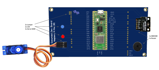
Ganymed Entwickler Board
Einfach aber komfortabel und preiswert soll es sein. Und es soll bspw Schülern heflen elektronische Projekte zu realisieren.
Programmieren lernen und gleich ein paar tolle Projekte umsetzen. Aber keine offene und wilde Verkabelung, denn das ist in der Regel ja übliche Praxis. Das war die Idee hinter dem Ganymed Dev Board. Ein guter Ansatz um selbst mal ein eigenes Board zu entwickeln und es fertigen zu lassen. Keine Großserie, sondern maxiaml kleine Stückzahlen. Und am 14. Januar 2023 war der erste Prototyp fertig.
Der Projektname Ganymed war schnell gefunden, das Layout designed und die Produktion der Prototypen angeschoben. Das neuen "Ganymed Dev Board" ist erstmal "nur" ein Erweiterungsboard und damit wird es einfacher und komfortabler seinen Versuchsaufbau sauber einzurichten. Flexibilität und eine bessere Sicherheit durch weniger Verkabelung zu den wichtigsten Bauteilen. Speziell ausgelegt für den Raspberry Pi Pico oder Pico W. Die Microcontroller der Raspberry Pi Foundation UK eignen sich hervorragend für diese Aufgabe. Tolle Möglichkeiten zum kleinen Preis.
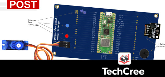
Die Leiterplatine erlaubt die Bestückung von beispielsweise einem BME280 Sensor und LED's, sowie einem Buzzer und einem SG90 Servo. Das ermöglicht schon die ersten wichtigen Projekte umzusetzen. Weitere Pin-Outs stehen zudem frei zur Verfügung. Das Ganymed Dev Board ist aber nur die erste Erweiterungsplatine mit einem ganz speziellen Layout. Weitere sind derzeit in Planung und es können ggf. auch die individuellen Wünsche eines Lehrers berücksichtigt werden.
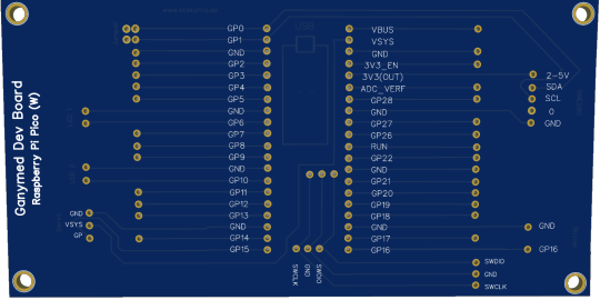
Derzeit gibt es erstmal ein paar Prototypen. Die sind dann vorbestückt mit Steckleisten für die Aufnahme eines Raspberry Pi Pico oder Pico W. Auch zwei LED sind bereits montiert (optional mit und ohne Wiederstände). Andere Bauteile können über die vormontierten Pins gesteckt werden. Bei den LED ist die Bestückung mit Wiederständen für eine längere Lebenszeit der LED zu empfehlen. Durch die Steckleisten für den Microcontroller kann flexibel entschieden werden ob ein Pico oder ein Pico W verwendet werden soll. Die Microcontroller können so jeder Zeit ausgetauscht werden.
Der Servo selbst und auch das "Wetterstations Modul" (Sensor BME280) und der Buzzer werden wohl zunächst nicht vormontiert sein. Auf Wunsch wäre aber auch das kein Problem oder um auch hier auf Kabel zu verzichten kann an Stelle von einer PIN Leiste auch eine Steckleiste vormontiert werden. Letztlich ist die Frage, ob die Lötarbeiten Teil des Schulprojektes sein sollen. Dies schlägt sich entsprechend dann auch im Preis nieder.
Der Demo-Code auf Basis von Micropython ist zwar bereits verfügbar (https://github.com/techcree/ganymed.git), wird sich aber ggf. noch anpassen oder ergänzen. Auch sind etwaig norwendige Bibliotheken ggf. noch zu installieren, wobei die IDE Thonny für die Programmierung zu empfehlen ist. Diese ist für Chromebooks unter Linux und andere Betriebssysteme geeignet. Auch die passende .ufw Datei muss natürlich noch installiert werden. Später soll alles was an Software nötig ist auf Wunsch auch auf dem Pico bereits vorinstalliert sein.
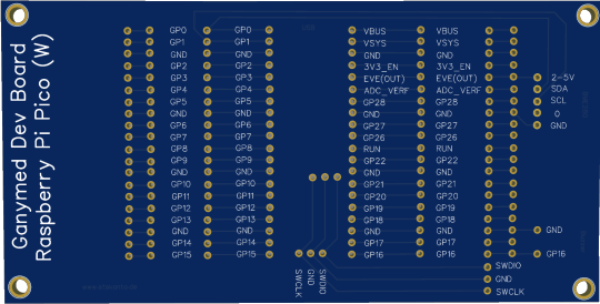
Dieses Erweiterungs-Board soll für Bildungseinrichtungen bezahlbar sein und wird voraussichtlich ab ca. 3-5 Euro kosten. Ohne Bestückung von elektronischen Bauteilen und natürlich auch ohne Raspberry Pi Pico oder Pico W. Komplett ist wohl je nach Stückzahl mit ca. 20 Euro zu rechnen. Andere Layouts wie im nachstehend Bild zu sehen sind grundsätzlich kein Problem. Das Ganymed wurde in mehreren Varianten, als sogenannte Erweiterungsplatine designed. Das Layout ist abhängig von der später gewünschten Verwendung.
Das Ganymed Dev Board ist das erste Projekt dieser Art aus der Feder von STSKANTA.de. Sicher aber nicht das Letzte. Es ist wohl der Beginn einer "erweiterten" Leidenschaft für den Raspberry Pi Pico.
0 notes
Text
From Beginner to Robotics Pro: Exploring the Best Arduino Kits for Every Skill Level
Arduino is an open-source platform used for building electronics projects. It consists of both hardware and software components that enable users to create a wide range of projects, from simple LED light displays to advanced robots. One of the best things about Arduino is that it has a variety of kits available, which cater to different levels of expertise and project requirements. In this blog, we’ll explore some of the most popular Arduino kits available in the market.
Nano Ultimate Starter Kit
The Nano Ultimate Starter Kit is a comprehensive starter kit that includes everything a beginner would need to get started with Arduino. It comes with an Arduino Nano board, which is a compact version of the popular Arduino UNO board. The kit also includes a variety of components, such as LEDs, resistors, sensors, and a breadboard, to name a few. The kit also includes a guidebook that provides step-by-step instructions on how to build various projects using the components included in the kit. This kit is an excellent choice for beginners who are just getting started with Arduino.
Grove Beginner Kit
The Grove Beginner Kit is another excellent choice for beginners. It is a plug-and-play kit that includes a Grove Base Shield and a variety of Grove modules, such as an LED, a button, a rotary potentiometer, and a buzzer, to name a few. The kit also includes a guidebook that provides step-by-step instructions on how to build various projects using the Grove modules included in the kit. This kit is an excellent choice for beginners who prefer a plug-and-play option.
UNO 21-in-1 Starter Kit
The UNO 21-in-1 Starter Kit is an all-in-one starter kit that includes an Arduino UNO board and a variety of components, such as LEDs, resistors, sensors, and a servo motor, to name a few. The kit also includes a guidebook that provides step-by-step instructions on how to build 21 different projects using the components included in the kit. This kit is an excellent choice for beginners who want to explore a variety of projects using different components.
Robotics Intermediate Kit
The Robotics Intermediate Kit is an advanced kit designed for those who have some experience with Arduino and want to build more complex projects. The kit includes an Arduino Mega board, which is a more powerful version of the Arduino UNO board, and a variety of components, such as a motor driver, ultrasonic sensor, and a servo motor, to name a few. The kit also includes a guidebook that provides step-by-step instructions on how to build various robotics projects, such as a robot arm and a line-following robot. This kit is an excellent choice for those who want to take their Arduino skills to the next level and build advanced robotics projects.
Conclusion
Arduino has a wide range of kits available, catering to different levels of expertise and project requirements. The Nano Ultimate Starter Kit and the Grove Beginner Kit are excellent choices for beginners, while the UNO 21-in-1 Starter Kit is an all-in-one kit that allows beginners to explore a variety of projects. The Robotics Intermediate Kit is an advanced kit designed for those who want to build complex robotics projects. Whatever your skill level or project requirements, there is an Arduino kit available to meet your needs.
0 notes
Last Seen Blogs

study-man
studyblr

fixerbuenosaires
Fixer in Buenos Aires


amiskinnyyet2323
I Just Wanna Be Pretty

howardtracie99-blog
cooking with tray