#breadboard computer
Explore tagged Tumblr posts
Text
How a Computer Works - Part 3 (Miniaturization and Standardization)
For anyone just joining in, I'm writing a series of posts explaining perhaps haphazardly all there is to know about how a computer works, from the most basic fundamental circuitry components to whatever level of higher functionality I eventually get to. As explained in the first post on this subject, I am doing this just in pure text, so that if you are inclined you can straight up print these posts out or narrate them onto some audio tape or whatever and have full access to them should every computer in the world suddenly collapse into a pile of dust or something. Part 1 mainly covered the basic mechanical principles of circuitry and how to physically construct a logic gate. Part 2 covered logic gates in detail and how to use them to create a basic working architecture for a general purpose computer. Today we're going to be talking more about what you're looking at when you crack a machine open so you can make sense of all the important fiddly bits and have maybe a starting point on how to troubleshoot things with a multimeter or something.
Before getting into it though, I do have to shake my little donation can again and remind you that I do not know how I am going to get through the winter without becoming homeless, so if this is valuable to you, I'd appreciate some help.
Boards of Bread and Printed Circuits
With the things I've explained so far, you could totally build a computer right now, but it'd be a bit messy. You can totally buy resistors, transistors, capacitors, and diodes by the bagful for basically nothing, and cheap rolls of insulated wire, but there's all these long exposed pins to cut short and soldering things in mid-air is a messy nightmare and you'd just have this big tangle of wires in a bag or something that would almost certainly short out on you. So let's look into ways to organize stuff a little.
If you start playing around with electronics on your own, one of the first things you want to hook yourself up with besides raw components and wires is a breadboard or 12. And if you're watching people explain these things with visual aids, you'll also see a lot of them, so it's good to know exactly what they are and how they work. Your standard breadboard is a brick of plastic with a bunch of little holes in it. Incidentally, the name comes from how the first ones were literally just named after the wooden cutting boards for slicing bread people recycled to make them. Inside these holes there's some pinching bits of conductive metal which connect to each other in a particular way (pretty sure you can just see the strips that connect one if you pry the bottom off), so you can just jam a thing wire or prong into a hole, have it held in place, and make a connection to every other hole its connected to on the other side.
There is a ton of standardization to all of this. The holes should always be 0.1 inches apart () and split into two big grids. Everyone I've ever seen has 63 rows, each with 5 holes labeled A-E, a shallow channel through the middle of the board, and then another 5, F-J, and we generally have numbers printed every 5 rows. Down underneath, for any given row, the set of 5 pins on each side of the channel are connected. So, holes 1A, 1B, 1C, 1D, and 1E are all connected to each other, and nothing else. Holes 1F, 1G, 1H, 1I, and 1J are also connected to each other. There's no connection though between 1E and 1F, or 1A and 2A.
Most breadboards will also have a couple of "power rails" along the sides. These are just going to be labeled with a long red line and +, and a long blue or black line and -, and have holes in 2x5 blocks staggered out. With these, all 25 or 50 or whatever holes near the red + line connect with each other, and all the ones near the black line connect with each other. The gaps every 5 holes don't serve any purpose beyond looking different enough from the big grid so you hopefully don't mix it up and forget that these ones all connect down the length, and not in in little clumps across the width like everything else. The idea, for the sake of convention, is you plug a wire connected directly to the positive side of your battery or DC adapter or whatever into any red line hole, the negative side to any blue/black hole, and then tada, you can make a circuit just by plugging a wire in from red to a normal grid line, whatever bits you want span from that grid line to another, and eventually you connect the far end back anywhere on the black/blue line.
With a nice circuit board, there's also little snap-together pegs along the sides, and the power rails are just snapped on with those. So you can just kinda cut through the backing with a knife or some scissors, snap those off, connect multiple boards together without redundant power rails in the middle, and then just have these nice spare long lines of linked sockets. In the computer I'm building on these, I'm just using spare power rails for the bus. Oh and the big grooved channel down the middle also has a purpose. Bigger electronic components, like our good good friend the integrated circuit, are generally designed to be exactly wide enough (or more, but by a multiple of 0.1 inches) to straddle that groove as you plug their legs into the wires on either side, so they nicely fit into a breadboard, and there's a handy gap to slide something under and pry them off later on.
Typically though, you don't see breadboards inside a computer, or anything else. They're super handy for tinkering around and designing stuff, but for final builds, you want something more permanent. Usually, that's a printed circuit board, or PCB. This is pretty much what everyone's going to picture when they think about the guts of a computer. A big hard (usually) green board with a bunch of intricate lines, or "traces" running all over made of (usually) copper. And maybe with some metal ringed holes punched all the way through (they call those vias). These tend to look really complicated and maybe even a little magical, but they're honestly they're just pre-placed wires with a sense of style.
Most of the material of the board is insulated. The copper traces conduct real well, and manufacturers have done the math on just how close together they can be run without connecting to each other in places you don't want. The holes that go all the way through are for either plugging other bits in that tend to come with long legs you maybe want to keep intact, or just ways to run a trace through to the other side, where we often have traces on the back too to maximize our space. Most of what makes them look all cool and magical is how the traces run as close packed as possible to conserve space, and tend to only turn at 45 degree angles, which is just an artifact of how the machinery used to etch them out sued to be iffy about anything else.
So tada, you have all your wires pre-stuck to a nice sturdy board, and maybe even have labels printed right on there for where you solder all the various components to finish the thing. Oh and when you hear people talk about like, motherboards and daughterboards? The big main board you have for everything is a motherboard. Sometimes you need more than that, so you make smaller ones, and connect them up ether with some soldering or cartridge style with end-pins sliding snugly into sockets, and those we call daughterboards.
Integrated Circuits, or as they're also known, "chips"
The last thing you're likely to find if you crack open a computer, or just about any other electronic device that isn't super old or super super simple, are integrated circuits. Generally these are think black plastic bars that look like you'd maybe try to awkardly use them to spread cheese or peanutbutter on crackers in a prepacked snack or something, with rows of tiny little legs that running along either side. Kinda makes them look like little toy bugs or something. Sometimes they're square with pins along every edge, because sometimes you need a lot of pins. These are integrated circuits, or microchips, or just chips, and wow are they handy.
Sometime back in the 60s when people were really getting their heads around just how ridiculously small they could make electronic components and still have them work, we started to quite rapidly move towards a point where the big concern was no longer "can we shrink all this stuff down to a manageable size" and more "we are shrinking everything down to such an absurdly tiny size that we need to pack it all up in some kind of basically indestructible package, while still being able to interact with it."
So, yeah, we worked out a really solid standard there. I kinda wish I could find more on how it was set or what sort of plastic was used, but you take your absurdly shrunken down complex circuit for doing whatever. You run the teensiest tiniest wires you can out from it that thicken up at the ends into standard toothy prongs you can sink into a breadboard or a PCB with that standardized pin spacing, and you coat it all in this black plastic so firmly enveloping it that nothing can move around inside or get broken, hopefully.
And honestly, in my opinion, this is all TOO standardized. The only real visible difference between any two given integrated circuits is how many legs they have, and even those tend to come to some pretty standard numbers. They're always the same size shape and color, they all have the same convention of having a little indented notch on one side so you know which end is which, and they all seem to use just the worst ink in the world to print a block of numbers on the back with their manufacturer, date of assembly, a catalog number, and some other random stuff.
For real if there's any real comprehensive standard for what's printing on these, I can't for the life of me find it. All I know is, SOMEWHERE, you've got a 2 or 3 letter code for every manufacturer, a number for the chip, and a 4 digit date code with the last 2 digits of the year, and which week of that year it was. These three things can be in any order, other things can also be on there, probably with zero spacing, and usually printed in ink that wipes away like immediately or at least is only readable under really direct light, it sucks.
Once you know what a chip is though and look up the datasheet for it, you should have all sorts of handy info on what's inside, and just need to know what every leg is for. For that, you find which end has a notch in it, that's the left side, sometimes there's also a little dot in the lower left corner, and hopefully the label is printed in alignment with that. From there, the bottom left leg is pin 1, and then you count counterclockwise around the whole chip. You're basically always going to have positive and negative power pins, past that anything goes. You can cram a whole computer into a single chip, yo can have someone just put like 4 NAND gates on a chip for convenience, whatever.
OK, but how do they make them so small?
OK, so, mostly a circuit we're going to want to shrink down and put on a chip is just gonna be a big pile of logic gates, we can make our logic gates just using transistors, and we can make transistors just by chemically treating some silicon. So we just need SUPER flat sheets of treated silicon, along with some little strands of capacitive/resistive/insulating material here and there, and a few vertically oriented bits of conductive metal to pass signals up and down as we layer these together. Then we just need to etch them out, real real small and tight.
And we can do that etching at like, basically infinite resolution it turns out. It just so happens we have access to special acids that eat through the materials we need them to eat through, but that only work when they're being directly hit with fairly intense UV light. And a thing about light is when you have say, a big cut out pattern that you hold between a light and a surface, it casts a shadow on it... and the scaling of that shadow depends entirely on the distances between the light, the pattern, and the surface. So if you're super careful calibrating everything, you can etch a pattern into something at a scale where the main limiting factors become stuff like how many molecules thick things have to be to hold their shape. Seriously, they use electron microscopes to inspect builds because that's the level of tininess we have achieved.
So yeah, you etch your layers of various materials out with shadow masks and UV acid, you stack them up, you somehow align microscopic pins to hold them together and then you coat the whole mess in plastic forever. Tada. Anything you want in a little chip.
ROMs, maybe with various letters in front
So there's a bunch of standard generally useful things people put into ICs, but also with a computer you generally want some real bespoke stored values with a lookup table where you'll keep, say, a program to be run by feeding whatever's inside out to the bus line by line. For that we use a chip we call Read Only Memory, or ROM. Nothing super special there, just... hard wire in the values you need when you manufacture it. Manufacturing these chips though is kind of a lot, with the exacting calibrations and the acid and the clean rooms and all. Can't we have some sort of Programmable ROM? Well sure, just like build it so that all the values are 1, and build a special little thing that feeds more voltage through than it can handle and physically destroy the fuse for everything you don't want to be a 1.
OK that's still kind of a serious commitment. What if I want to reuse this later? Oh, so you want some sort of Erasable PROM? OK someone came up with a funky setting where you overload and blow out the fuses but then if you expose the guts of the chip to direct UV light through this little window, everything should reform back to 1. Just like, throw a sticker on there when you don't want to erase it. Well great, but can we maybe not have me desolder it and take it out to put under a lamp? Oh la de da! You need Electronically Erasable PROMs? EEPROMs? I guess we can make THAT work, somehow. They're still gonna be slow to write to though, can't have anything. I mean, not unless we invented like, flash memory. Which somehow does all this at speeds where you can use it for long term storage without it being a pain. So that's just kinda the thing we have now. Sorry I don't quite get the principles behind it enough to summarize. Something about floating components and needing less voltage or whatever. Apparently you sacrifice some read speed next to older options but hey, usable rewritable long term storage you just plug in, no jumping through extra hoops.
So OK. I think that's everything I can explain without biting the bullet and explaining ALUs and such. Well, there's keyboards (they're just buttons connecting input lines), monitors (these days, LEDs wired up in big grids), and mice (there's spokes in wheels that click X times or cameras checking the offset values of dust on your desk or whatnot).
Maybe throw me some money before we move on ?
CONTINUED IN PART 4
#computers#computer science#pcb#printed circuit board#integrated circuits#microchip#breadboards#education#electronics
56 notes
·
View notes
Text
hey uh, i’m getting into guitar pedal building and breadboarding, i have all the things i need (i think) but really no clue on where to ask questions about stuff. every youtube video i watch takes some stuff for granted and my own research skills aren’t great to i’m here to ask all you nerd girlies.. pls help how do i know what side of the input jack goes to ground 😭😭
#computer#breadboard#technology#tech girls#transfem#trans#wlw#transgender#trans pride#sapphic#gay girls#lesbians#guitar#effects
2 notes
·
View notes
Text
Honestly Barbara is lucky with how corrupt Gotham is, in no other city could they pull permits to do the huge electrical upgrades necessary to support Oracle to a building like the Clock Tower
#these are the kind of thoughts that only i have lmao#batfam#wow a cross over event!!#dc#bread talk#barbara gordon#oracles plug loading must be Massive#every time i look at her set up im like yeah thats a whole panelboard Just for that one computer lmao#hot girls when they pull an entire 100 amps down for their night time activites#especially if the clock tower is in old gotham they might have had to replace the overhead for the entire block lmao#oh lord#what if gotham has underground ducting#fuckkkkk that#at barbara in the 90s comics girly thats not “some gift money” thats “massive infrastructure overhaul” money#bread critiques the gotham city electrical infrastructure more at 11#breadboarding
7 notes
·
View notes
Text
youtube
0 notes
Note
Cactus fascinates me, does it run on code similar to an existing instruction set or is it completely original on that front?
What can you do with it? What's it's storage?
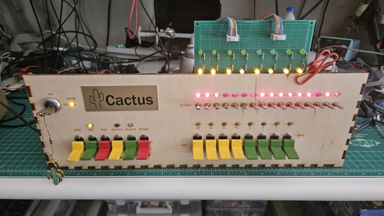
Both the Cactus (the original wooden prototype from years ago) and the new PCB Cactus(es) are essentially derived from a minimal 6502 computer design by Grant Searle for their core logic. Here's what that would look like on a breadboard:
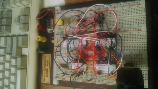
There isn't much to it, it's 32K of RAM, 16K of ROM containing Ohio Scientific's version of Microsoft BASIC, a 6850 ACIA for serial interaction, some logic gates, and of course a 6502 microprocessor (NMOS or CMOS, doesn't matter which). You hook it into a terminal and away you go.
Grant's design in turn can be best described as a distilled, modernized version of the OSI Challenger series of computers. Here's an OSI-400 and a Challenger 4P respectively:
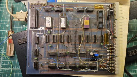

The left one is a replica of the 400 circa 1976, also called the Superboard. It was affordable, endlessly reconfigurable and hackable, but ultimately very limited in capabilities. No BASIC, minimal monitor ROM you talk to over serial, but you could connect it to a bus to augment its features and turn it into a more powerful computer.
Whereas the OSI C4P on the right from about 1979 has more RAM, a video card, keyboard, BASIC built in, serial interface, cassette tape storage, and that's just the standard configuration. There was more room to expand and augment it to your needs inside the chassis (alot changed in 3 years for home computer users).
Grant's minimal 6502 design running OSI BASIC is a good starter project for hobbyists. I learned about the 6502's memory map decoding from his design. I modified and implemented his design on a separate cards that could connect to a larger backplane.
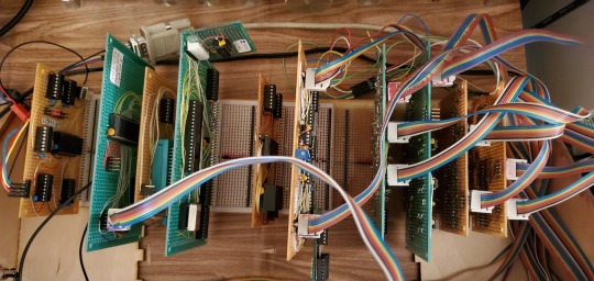
Here are the serial, ROM, RAM, and CPU cards respectively:
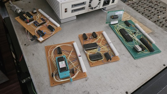
Each one is 100% custom, containing many modifications and fixes as I developed the design. However, that's only half of the computer.
I really wanted a 6502 machine with a front panel. People told me "nobody did that", or couldn't think of examples from the 1970s but that seemed really strange to me. Especially since I had evidence to the contrary in the form of the OSI-300:
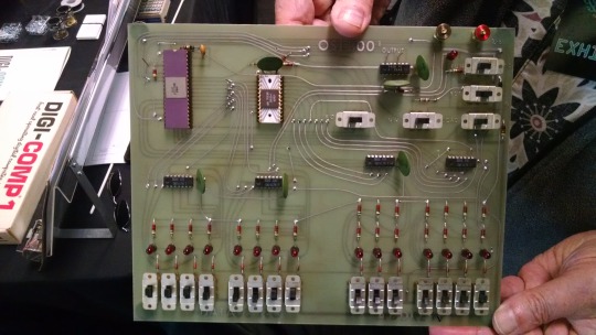
This one I saw at VCF West back in 2018 illustrates just how limited of a design it is. 128 bytes of RAM, no ROM, no serial -- just you, the CPU, and toggle switches and LEDs to learn the CPU. I was inspired the first time I saw one in 2015 at VCF East, which is probably when this whole project got set in motion.
Later that year I bought a kit for a miniature replica OSI-300 made by Christopher Bachman, and learned really quickly how limited the design philosophy for this particular front panel was. It was a major pain in the ass to use (to be clear, that's by OSI's choice, not any fault of Christopher in his implementation)

So... I designed my own. Took awhile, but that's the core of what the Cactus is: my attempt at experiencing the 1970s homebrew scene by building the computer I would have wanted at the time. Over half of the logic in the Cactus is just to run the front panel's state machine, so you can examine and modify the contents of memory without bothering the 6502. I added in all of the things I liked from more advanced front panels I had encountered, and designed it to my liking.
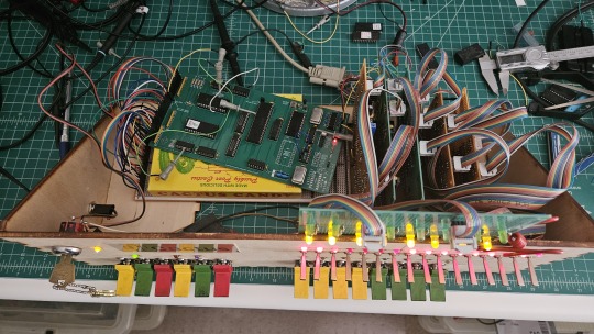
Here's the original front panel, accompanying logic, and backplane connected to the modern single board computer (SBC) version of the machine:
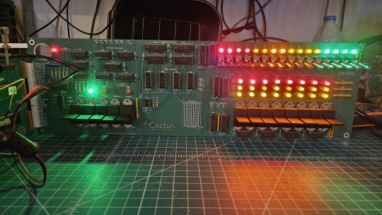
And here's the new Cactus SBC working with the new front panel PCB, which combines the logic, physical switch mountings, and cabling harnesses into a single printed circuit board.
So, what can you do with it? Pretty much the same things I do already with other contemporary 1970s computers: play around in BASIC, fire up the occasional game, and tinker with it.
I've got no permanent storage designed for the Cactus as yet, it's been one of those "eventually" things. The good news is that a variety of software can be ported to the hardware without too much trouble for an experienced hobbyist. A friend of mine wrote a game called ZNEK in 6502 assembly which runs from a terminal:
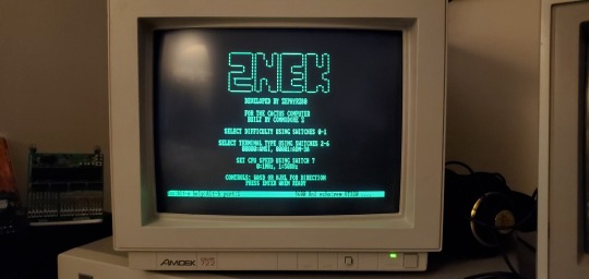
Right now, you have to either toggle in machine programs from the front panel from scratch, burn a custom ROM, or connect it to a serial terminal to gain access to its more advanced features:

Here's it booted into OSI BASIC, but I have also added in a modern descendant of Steve Wozniak's WOZMON software for when I need to do lower level debugging.
I've also got a video card now, based on the OSI-440. I have yet to implement a keyboard, or modify BASIC to use the video board instead of the serial connection. Even if I did, screen resolution is pretty limited at 24x24 characters on screen at once. Still, I'm working on that...
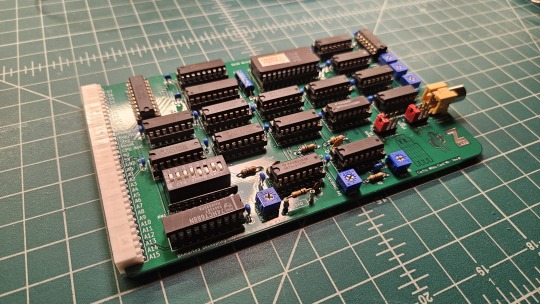

Anyway, I hope that answers your question. Check the tags below to see the whole process stretching back to 2017 if you're curious to learn more of the project's history. I'm also happy to answer any more questions you might have about the project.
267 notes
·
View notes
Text
are there any decent hand-assembleable computer kits out there? like, 6502 or Z80 based systems that provide parts and pcb unassembled. i want to mess with simpler computers but also don't want to buy an expensive 45 year old machine. looking at the ben eater breadboard system but that's breadboarded so idk if i'd enjoy the assembly as much
#xfce post#old computers#retro tech#6502#pleasepleaseplease i wanna solder one up and mess around with BASIC
15 notes
·
View notes
Text
Stepping Backwards a Bit (or 24)
I was looking for a simpler project. My recent 68030 work has been challenging and really pushing the limits of what I can do. I wanted something I could work on, but perhaps where someone else has already worked out the hardest parts.
I find laying out PCBs to be rather relaxing. It's one of those repetitive, almost meditative tasks, like needlepoint or whittling. The kind of hobby where I can turn on some music or a comfortable old TV show, zone out for a few hours, and wake up to this new thing that I created.
Debugging however is very mentally taxing, and the design work required to have a functional schematic to create a PCB for is an active whole-mind prices. So what I really needed was an existing project I could design a board for.
Enter [Grant Searle]. If you're not familiar with [Grant Searle], he has excellent designs for breadboard computers with a very minimal parts count. I studied his minimal Z80 design when I was first starting to build my own computers and learned a lot from it. I highly recommend his work for anyone who is interested in learning how to build their own computer but doesn't know where to start.
I was recently given a Rockwell 6502 CPU pulled from a dead LED marquee. I've never actually worked with 6502, so this seemed like a good time to try building Grant's 8-chip (or 7-chip) 6502 computer.
A few hours later, I had a PCB design completed, gerbers generated, and an order placed. Less than $5 for 5 boards, including shipping. A couple weeks later they arrived in the mail.


I did end up making a few modifications to [Grant]'s design. Instead of a clock circuit made from a discrete crystal and a couple inverter gates, I used a TTL oscillator because I've always found them to be more reliable. I also added support for an FTDI USB Serial adapter chip so that the board can be used with a modern computer as a terminal. And finally, since a PCB is much harder to add new components to relative to a solderless breadboard, I added an expansion header. All of it wrapped up in a compact PCB with lots of helpful silkscreen marking.

I realized after I had ordered the PCBs that the 16kB ROM chips [Grant] used are no longer manufactured or readily available. I have plenty of 8kB EEPROM chips on hand however. Thankfully the OSI BASIC interpreter [Grant] ported to this design fits within 8kB, so I was able to make a few adjustments and re-assemble it to work with the ROM chips I have on hand.
After a small glitch with my EEPROM programmer, it works!

It's quite a change going from my 33MHz+ 68030 to this tiny 6502 running at just under 2MHz. The BASIC text-based Mandelbrot renderer that completes in seconds on my 68030 takes four and a half minutes on the 6502. Not bad at all, considering my bus-impaired 68000 build takes 9 minutes to do the same.
This was a fun little project. It was a nice little break from some of the more difficult projects I've been working on. I have shared the project on GitHub for anyone who might want to take a look.
I hope to have this project with me this weekend, June 14-16, 2024 at Vintage Computer Festival Southwest. I'll be at table 207 in the Tandy Assemble hall, just across the street from the main exhibit hall.
30 notes
·
View notes
Text
SYNTAX x READER
Content: Fluff (i think)
Posted from my AO3 account to here
Enjoy :>
———————————————————————
It was not a good day, to say the least.
You had set your drink down on a bed of notes by mistake, so now there’s a ring of water decorating those rather important papers, your sparring match with Huntsman left you feeling more sore than usual, and your mood just wasn’t that great to begin with.
So now you’re stuck in Syntax’s room, having been sent to work on some printed circuit board assemblies with him. Not that that was bad, most of the time you loved working with someone who could match your intellect with computer and other electronic hardware.
It’s just for some reason you coudn’t get this stubborn LED to work properly.
Which was strange, to say the least. As this had never happened before, you struggling this badly over something so utterly simple. It was frustrating to you, so much so that the pen in your hand you were using for schematics was now brutality making contact with the table.
The pen nib was practically destroyed, but you kept going, finding a strange satisfaction in how it cracked under the pressure. But rather quickly Syntax notices this, looking over at you from his seat with an expression of slight concern and something akin to amusement.
“You’re lucky I didn’t like that pen.” He muses, getting up from his seat to walk over to you. His movements are swift and confident, like always, but you can already feel the snarky remark or joke coming any second now.
After a moment or two, you finally respond.
“Yeah, I really don’t like it either.”
He hums in acknowledgement, seemingly thinking about something. He can practically feel your bad temper right now, and he knows you’re rather fond of jokes. So he decides to take a small risk, doing something he’d normally never even think about, but to be fair, he’s also curious as to what your reaction could be if he finally says something other than a smug remark.
“You know, I just have to say… think of that poor pen’s feelings, hm? How would you feel if I banged you on the table like that?” A little smirk forms on his face, and he leans against your work station, supporting himself with a hand.
Your eyes widen slightly, and then a grin slowly begins to cover your face. “Do you want the ‘appropriate’ answer, or the ‘down horrendous’ answer?”
Now it’s his turn to stammer, seemingly caught off guard. Syntax had expected nothing short of a ‘shut up’ to his comment, so when you said that, it left him stumbling to calculate a response. You take notice of his current embarrassed expression, deciding to have a bit of fun with this now.
“Oh, c’mon. You really walked into that one. For someone so intelligent, I would’ve figured you’d have realized the double meaning there,” You lean back in your swivel chair, lightly tossing the broken pen onto the surface of the workstation.
He just huffs, picking himself and his dignity off of the metaphorical ground.
“Well, I didn’t know I was speaking with someone whose mind occupies the entire gutter!”
“You gotta admit, that was funny,” You laugh, smiling like a fool at his reaction. He’s not genuinely mad, you can tell, but it’s still very silly.
Syntax just sighs, rolling his eyes and feigning annoyance. “You’re lucky you’re decent with hardware, otherwise I would’ve kicked you out of here already.”
This time around, he’s more careful as to not say anything that could be turned into a sexual joke. It’s not like he doesn’t enjoy it, but it’s more interesting for the both of them if he puts up a fight. But you do glance over at the ridiculously stubborn LED from earlier, feeling a little bit down again with how you weren’t able to get it to function correctly.
Before you respond to the technician, your hands find themselves moving with a new idea. The LED is replaced with a newer red one, after turning off the power to the prototyping breadboard of course. Then you switch the button back on.
It begins emitting light, like the other one was supposed to do.
You celebrate for a split second before turning back to Syntax, a pleased expression on your face. The original light is between your thumb and index finger now, and then you place it to the side.
“It appears this one is a dud, didn’t these come in yesterday though?” You ask curiously, wanting to make sure you’re remembering things right.
He hums out an answer with a nod alongside it. “Yes, but the Queen insisted we go for more… nominal resources.”
You nod as well, feeling a little bit annoyed with such actions. The cheaper the materials, the harder it will be to do things, not to mention the risk of something malfunctioning. Then if, or rather when something goes wrong, them two will be the ones taking the blame for it.
“Well, that sucks,” You mutter, looking over at the burnt out LED, then to the functioning one.
“Nothing we can do about it,” The spider demon just sits back down in his chair, beginning to clean the area.
You do the same.
20 notes
·
View notes
Note
I saw the post you did a while back about the electronic dice (firstly, super awesome and I love the way you got the random seeds).
I'm a computer science student but for the most part I only really do software. I have a raspberry pi pico and a breadboard but I've never been able to make it do more than light an LED, and I didn't understand how *that* worked. How do you get into that sort of thing? Or what was your path at least?
I started with software too, then I learned a bunch about mechanical and electrical stuff working on my car, and putting them together was kind of the obvious next step after that.
my early arduino projects were WS2812 LED things and simple single-motor contraptions. then in covid lockdown I built a 3D printer and my tinkering obsession amped up by several orders of magnitude.
11 notes
·
View notes
Text
Last time on this blog, I made an ATTINY85 flash an LED
This time I made it turn on two different LED’s with a simple push of a button! (Warning; video has pulsing LED’s)
[VIDEO ID: a breadboard with a PDIP8 ATTINY85 microcontroller on it. There is a button next to it, and two LED'S connecting away from it; A yellow and a green. When the video starts, the yellow turns on, but every time a white human finger pushes and holds the switch, the yellow turns off and the green turns on. END ID]
This program will turn one LED on, but if you push the button it will turn it off and activate the other LED. The LED’s will alternate who’s on and off, and this is directly controlled by the tact switch
This one took a bit to code because I forgot how computers count!! And I knew better too!! I had all the bytes coded for 1,2,3,4 counting when computers count as 0,1,2,3. Very embarrassing 😔 Alas, here’s the assembly code I made for it :)
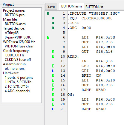
My next step is to make it count two pulses based on a toggled input. While one switch is pushed, count the other switch to see how many pushes it has before the first switch is released. Then, once it gets the count, flash an LED the same number of times.
15 notes
·
View notes
Text
DIY: Marauder with Screen and GPS For Flipper Zero
Many of you would have seen the humongous ESP32 add-on module with touch screen and GPS for Flipper Zero shared in discussion groups, forums, etc. Well, this tutorial will provide you with all the information you need to build one yourself.
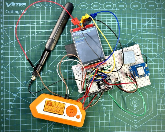
This build consists of mainly 4 parts. The TFT LCD 2.8" 240x320 SPI ILI9341 Touch Display cost me around US$5.50, the ESP32-WROOM-32U module cost around US$3, the NEO-6M GPS module cost around US$2.20 and an 8dbi 2.4GHz Wifi Antenna which cost around US$2. All of these parts can be easily found in online marketplaces like Aliexpress, Amazon, etc. Here is how you need to wire them up together. How you wish to lay this out or mount on a prototyping board is entirely up to you. As long as the connections are correct, you are good to go. The GPS module is optional, and mainly, it's used for the war driving functionality.
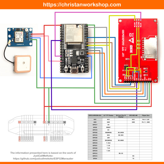
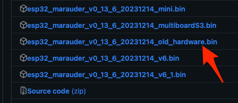
Next, you need to download all the firmware needed from here. Please download the Bootloader, Partitions, Boot App and Firmware files for v4 (Yes, v4 files, not any others) and save it on your computer.
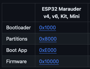
Now, press and hold the BOOT button on your ESP32-WROOM-32U module and connect it to your computer using a data-capable USB cable (some USB cables can only charge), then let go the BOOT button. Open Google Chrome or Microsoft Edge browser and go to ESPWebTool. Click the CONNECT button, then select the ESP32 usb serial connection. It should look something like below but can vary a little between different computers and operating systems.
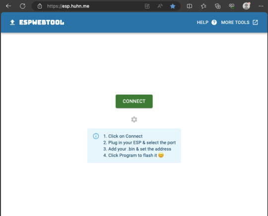
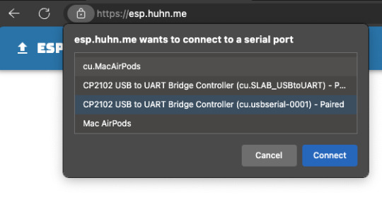
Select the firmware files for each slot exactly like below (take note of the 0x1000, 0x8000, etc. and their corresponding .bin files), then hit the PROGRAM button.
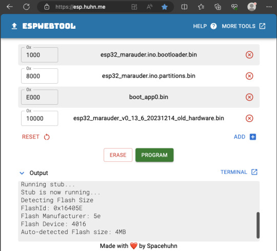
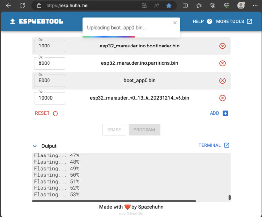
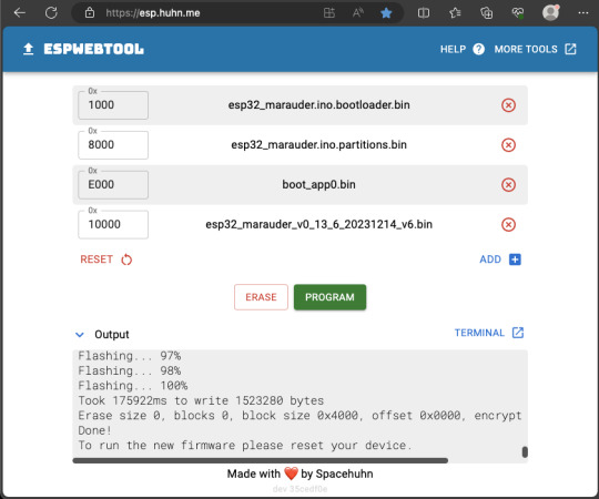
When completed successfully, you can unplug the USB cable from the ESP32 module and now you can connect your Marauder module to your Flipper Zero. Please ensure that your Flipper Zero is turned off before you connect it, and also turn off your Flipper Zero before disconnecting it. The 3.3V pin is also used by your Flipper Zero's SD card reader and connecting/disconnecting external modules that use this pin while the Flipper Zero is on can potentially corrupt the SD card. So, if everything went according to plan, your Marauder module should boot up and everything should look like below.
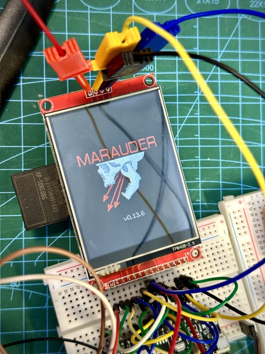
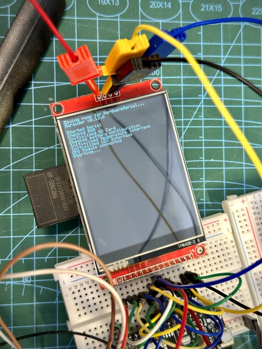
NOTE: If your Marauder boots up, but when you try to touch the screen and get no response, try tapping around the bottom part of your screen and see if the touch panel seems to be in inverted position from the actual display. Should this happen to you, just flash your ESP32 module again following the steps above, but use the v6 firmware. This should resolve the issue.
In this build, I just prototyped this on breadboard, but you can of course make it permanent by soldering it on to a prototype board and 3D print a case for it. This setup is essentially just using the Flipper Zero as a battery pack, instead of using the Flipper Zero to control Marauder. The large screen does make some things easier to do, compared to the small screen of the Flipper Zero, and there may be some functionality (not much) that is not currently in the Flipper Zero Marauder companion app. Here is a video showing the different menus in Marauder.
Personally, I don't think I will actually want to bring something so big around with me, along with my Flipper Zero. I think what makes Flipper Zero special is just how compact it is and all the different functionality cramped into it. This would probably be better off as a standalone unit by just hooking up a battery, but that's just me. Well, that's it for this tutorial. I hope you found this helpful. If you haven’t already done so, check out my Makers & Hackers Exchange Facebook group to learn more from other Flipper Zero users.
Here's a good intro to Marauder if you are unfamiliar.
youtube
15 notes
·
View notes
Text
All of the crowdstrike drama is really making me thankful I never found that set of jumper wires for my breadboard and became an electrical engineer
The worst I can do as a marine engineer is blow up the engine and start an uncontrollable fire which destroys the ship. Very low stakes compared to BSODing every hospital’s computer system
Anyway very glad I’m floating around the North Sea while all of this is going down
4 notes
·
View notes
Text
A controller with a scroll wheel, you say?
Well this is a little funny. Yesterday I posted the first part of a series of post on the fine details of how computers work, mentioning how I've been looking into this as part of a personal project I've been working on, and today I wake up to see Masahiro Sakurai posting a youtube video lamenting the lack of... this exact thing I'm working on.
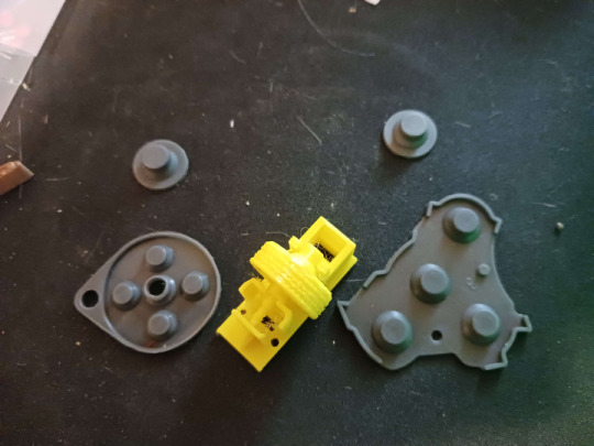
Apologies for how much cat hair is in this photo, that's a bit of an occupational hazard, but this here is a photo I took back in September when most of the parts I had to order were in for the prototyping of this thing:
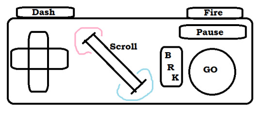
That's a really bad MS Paint mockup, but yeah. I'm designing my own game console, and one of the key features is a big ol' scroll wheel right in the center of the controller. Another is that I'm planning to just put all the designs of the circuit boards and 3D printer files for the casing/buttons up online for free, making it this totally open DIY thing where anyone who's a big enough nerd can just make a couple downloads, order some dirt cheap components, and build their own copy of the system (or people with better setups than me can build and sell them, whatever). So I'm not super worried about anyone stealing my ideas or whatever, but I WOULD like to establish a standard and all that, and figured it was worth noting that this is something I've been slowly working towards for like a year or two now, and didn't just get the idea from this video:
youtube
But yeah, now that the idea's out in the public consciousness, here's the plan for the controller (that I was planning to keep under my hat until I had a working prototype and some demo software sometime next year).
First off, the plan is that this is to be the standard controller for a whole console I'm also plucking away at designing, which is a bit more ambitious of a project, so I figure I might as well make it compatible with something that's already out there. So specifically, I'm designing this so that you can take one, plug it right into an SNES (or with a different connector at the end, an NES, because turns out they use the exact same input handling standard and it's just the shape of the plastic on the end that differs), and have it just work. Or mostly work anyway. I'm hoping I can process a signal out of the scroll wheel in a way that it either just needs the 3 extra bits of the input signal I don't have buttons for in my design (more on that later) or failing that, I can get it to output the same sort of signal as one wheel in the SNES mouse, which just rides along the second data line very few things use. I think that plan might break multitap compatibility and require an extra chip on the controller PCB, but it would leave this slightly more compatible with existing games on the same hardware. I might also do something weird with the button mapping to be sure NES select is on a shoulder and it works right out of the box with that whole library.
Working out exactly how to handle signals from the scroll wheel happens to be the point I'm currently stuck on by the way. I got this baggie full of rotary encoders for just a few cents which... almost fit in my first draft 3D printed wheel housing, but I have NO documentation on them, not even a part number/manufacturer besides "H-9," the pins don't fit a breadboard, and I've kinda been scrambling for rent so I can't afford a nice multimeter or oscilloscope to poke around with. Plus again I need to redesign this wheel print to even get it to spin right, and... this was a gift from a friend with a printer who is Not Local. Solvable problem, just needs more time and/or outside expertise.
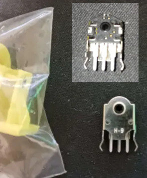
But yeah, once I have those kinks worked out, it should be easy enough to get a custom board design made, replicas of end-cap of the controller cord are another problem easily solved by ordering a 1 dollar part or 3D printing something. The actual cord might be tricky since I don't know where you actually order something like that from, but it should be easy enough for anyone who doesn't mind a little assembly work to put one of these together and have it good to go for any software made with it in mind, or retrogames where you don't mind a weird button count. So... what's the pitch on this scroll wheel anyway?
Well for starters, there's the stuff Sakurai got into this morning. Any sort of RPG or text heavy game can use it to quickly scroll through menu options, or stuff in a text-heavy game. You could also pan the screen with it, something a lot of early 16-bit games assigned to the shoulder buttons or holding up and down while getting used to the new options the hardware was giving them.
Past that, you'll notice in my design it's at a 45 degree angle. I might have to tweak it a little, but my thinking is for a game that uses it heavily, one thumb or the other can slide over easily enough (I'm going for a pretty compact overall design) so we can have some games where you take your thumb off the D-pad, and have this nice analogue steering wheel. Nice for fine control in a racing game, or if you want some little radio-tuning/safe-cracking sorta deal.
Alternatively, move your right thumb over, use the D-pad to steer, shoot and dodge or whatever with shoulder buttons, and use the wheel to rotate a turret for a twin-stick sort of game maybe.
Or just use it for the sort of stuff mouse based games stick on the scrollwheel. Changing weapons, changing powerups... I'm planning to officially label the directions "hot" and "cold" to encourage weird gimmicky things like... I dunno, a platformer where you have a thermostat in your controller you can always mess with, freeze water coming out of pipes, crank up flame jets? Have a shot charging mechanic where you just really crank it to get to max strength? Weird minigame stuff. There's some fun space to explore with it.
Then we have the rest of the design here... which basically comes down to me being just plain sick of how every controller made by anyone in the past... 20 years give or take has kind of the exact same layout? 4 good face buttons, a D-pad, 4 shoulder buttons, 2 sticks, and 1-4 annoying to reach tiny awkward middle buttons, and we're just kind of overdue for a change-up?
Like first of all, hey, this is just too many buttons. There's a ton of games that really only need a D-pad, and maybe 3 buttons (attack jump pause) and the two things that aren't fully standardized is how awkwardly placed the D-pad is and how awful and awkwardly placed the pause button is. Shoulder buttons can be nice, but I've never really felt like 4 of them awkwardly crammed on the rim has been really useful or ergonomic, and that's coming from someone who's been playing a ton of FF14, which gets more use out of them than anything else I could name. And really, aside from games doing fake twin-stick stuff and using the whole grid like a second D-pad, I'm having a really hard time thinking of any game I've ever played that really makes good use of 4 good face buttons? Like people will use them if they've got'em sure, but unless you do that keyboard style thing where you lay the controller on a table and use all your fingers, you can really only comfortably hit 2 face buttons without sliding your thumb away from them, maybe comfortably make a quick pivot to a third.
Also, really, a lot of designers just sort of feel compelled to map SOMETHING to every button, even if it's clear the design didn't really need them. So basically I figure I'll try kinda just taking a "less is more" approach here. Here's the buttons that it's comfortable to rest your thumbs and fingers on, here's a dedicated pause/menu button where people often stick a kind of redundant menu button, here's my gimmicky scrollwheel. That's it, work around that.
I'm also going a little Gamecube inspired (literally using replacement membranes for one in my prototype design, even). Gonna make a great big primary button and use different shapes for the other two. Trying to label these in a less arbitrary fashion than most. If shooting a gun is a thing you do in this game, and there isn't a real good reason not to, default it to this nice right trigger you can hold down all the time. If we're advancing through menus or jumping or holding down gas in a car, here's the big GO button. Need brakes, need to break stuff with a melee attack? Go back in a menu system? There's your other face button. Have a quick dash move or a run you hold down, let's just use the other shoulder.
So yeah. That's my controller. Need to work out the kinks on the scroll wheel, source a cord, and hopefully I can slap things together and this will be something you can just order bits for piecemeal and put together for like, $5-10 after shipping? Maybe less? The parts are shockingly cheap so far.
But yeah if anyone has any insight to the scroll wheel or cord issues, let me know. Also the whole thing is presently a tad back-burnered because I am in a serious financial crisis and I don't want to have electronics spread all over my table if I have to abruptly find a new place to live if I can't scrape next month's rent together. So as usual, donations are incredibly welcome.
2 notes
·
View notes
Text
Short sum for newbie system designer processor steps

Here are a few beginner projects for learning the ropes of customized computation architecture design:
Pana, a '4-4-4' instruction processor derived from Intersil 6100 & GaryExplains' but for 4-bit data. Uses the sixteen (16) RISC instructions shown by GaryExplains and only four (4) of its registers (ACC, PC, LN & MQ) as per of the Intersil 6100 specification. Doing as much work onto nibbles like an MVP Intel 4004 can, great as a BCD & Nibble data converter for later designs.
Tina, a barely expanded '4-4-8' processor derived from the "Pana" design, it uses more registers by adding twelve general-use registers (A-F, U-Z letters) and operate onto a single byte of data at a time. Great for two nibbles operations, byte-wise interoperability and 8-bit word compatibility with all sorts of modern processors from the seventies-onwards.
Milan, a '6-2-24' strong hybrid 8-bit / 12-bit processor derived from the "Tina" design, operating onto three bytes or two tribbles of data at once depending of use-case, while fitting in exactly 32-bit per instruction. Aimed at computing three 8-bit units, enabling 16-bit & 24-bit compatibility as well as up to two tribble operands. A great MVP implementation step towards my next own tribble computing architecture and a competitor to the Jack educational computer as shown in the NAND2Tetris courseware book.
When I am done with such, I will be onto three tribble-oriented architectures for lower-end, middle-end and upper-end "markets". Zara being lower-end (6-bit opcode, 6-bit register & 36-bit data = 48-bit instructions), Zorua being mid-end (8-bit opcode, 8-bit register and 48-bit data = 64-bit instructions) and Zoroark being upper-end (12-bit opcode, 36-bit register and 96/144-bit data (so either eight or twelve tribble operands worth of data) = 144/192-bit instructions, aiming to emulate close enough to an open-source IBM's PowerISA clone with VLIW & hot-swap computer architecture).
By the way, I haven't forgotten about the 16^12 Utalics game consoles and overall tech market overview + history specifications, nor have I forgotten about studying + importing + tinkering around things like Microdot & Gentoo & Tilck. I simply need to keep a reminder to myself for what to do first when I shall start with the computation engineering process. Hopefully that might be interesting for you to consider as well... Farewell!
EDIT #1
youtube
Tweaked and added some additional text & considering studying various aspects of Linux and overall copyleft / open source culture engineering scene, especially over Gentoo alternative kernels & hobby / homebrew standalone operating systems (GNU Hurd, OpenIndiana, Haiku... as well as niche ones like ZealOS, Parade, SerenityOS...) as to design a couple computation ecosystems (most derived from my constructed world which takes many hints from our real-life history) and choosing one among them to focus my implementation efforts onto as the "Nucleus" hybrid modular exo-kernel + my very own package modules collection. (Still aiming to be somewhat compatible with existing software following Unix philosophy principles too as to ease the developer learning cost in initial infrastructure compatibility & overall modularized complexity; Might also use some manifestation tips & games to enrich it with imports from said constructed world if possible)
2 notes
·
View notes
Text
back in electronics class, 100 years ago, we had this breadboarding program to draft out our projects. mostly we just made goofball messes of lights or drew pictures with wires.
but I figured out how to adjust the pitch and volume of the piezo buzzers. mapped out a scale. made a breadboard project that played 'Red River Valley' in the worst, most annoying noises possible. teacher hated it. classmates asked how to do it. class full of squeaking and honking computers. :3c
#whenk wonk WEENK weenk wonk whenk wonk weenk wonk wonk#this was high school so like. 2006#in between playing Halo demo on the school network and screwing around in the breadboarding program and autodesk inventor#we did in fact get our actual coursework done#but there was a lot of nonsense going on in those classes.#the electronics teacher had a metal box on his desk with the corner of a $20 bill under it. touching the box to pick it up gave a bad shock#students forgot? all the time?? and kept getting zapped???#good times
4 notes
·
View notes
Text
A while back, Sam over at Look Mum No Computer did an examiner/recreation of the early 1970s automated music system, the Psych-Tone. Designed by the legendary Don Lancaster and first appearing in the February 1971 issue of Popular Electronics (and a kit made available by SWTPC, the Southwest Technical Products Corporation), the Psych-Tone used early logic chips and transistors to play a number of different tunes based on the setting of various switches and potentiometers.
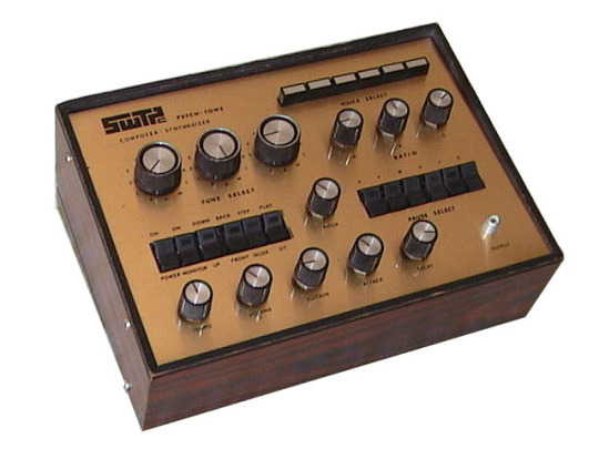
The core of the circuit is a pseudorandom sequence generator — a circuit that creates a single random sequence of 0s and 1s, and keeps it circulating. With six stages in the chain, the sequence is 63 steps long. The three selector knobs each pick where in the chain to listen, and when that value is 1, pass that through a potentiometer to set a partial pitch. The three partial values sum together to make a tune, which is played on an organ-like tone generator.
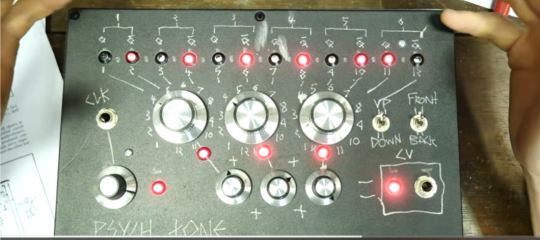
In explaining the device, Sam built a new version of the machine's sequencer section, using slightly newer chips and adding some LEDs to illustrate the functioning, for folks to play on synths with at his This Museum is (Not) Obsolete. Which got me thinking about doing something similar myself — building essentially the note generator as a random sequence creator for Eurorack.
Fortunately, in addition to Sam's video and the original article, Lancaster wrote up how to build these PRSGs, in varying lengths, in his book CMOS Cookbook; where the original used individual flipflops, this updated circuit lets you use shift registers (since one of those is effectively an internally-connected string of flipflops). To boil things down, by feeding certain of the output values back to the input through an XOR gate, a n bit shift register can cycle through a 2^(n-1) sequence, which can then be used in a number of different ways — basically anywhere you want something that's effectively random, but potentially repeatably so.
The circuit diagrams and tables given there have let me breadboard up something that I haven't yet tested, for a few reasons.
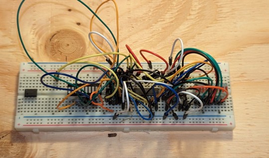
First, I'm feeling a little unsure as to how long to make the sequence. Obviously, if you make the sequence too short, it's too repetitive, but conversely, if it's too long, it's not going to be distinguishable from randomness. The original's length of 63 steps seems short, but the breadboarded circuit right now is set up for not 6, but 16 stages, which would yield a sequence length of 65,535 steps, which might be a bit much.
That's not more than something to work out in testing, though, which leads to reason two. Like with Sam's version, the one on the breadboard is meant to show the internal workings by using LEDs. And I've got a couple of nice, compact 10-segment bar graph LED displays on the breadboard, each one wired to 8 of the 16 stages. But LEDs can't handle just being plugged into a raw voltage; each one needs a current-limiting resistor to keep it from burning out. And while I could hook up 16 separate resistors on this breadboard, I don't wanna. I have — someplace around here — a nice little assortment of resistor arrays, chiplike affairs where eight identical resistors all connect to the same ground pin. Once I find them, I can watch the blinkenlights and get a better picture of the kind of sequences I'm dealing with.
(Your basic pseudorandom sequence generator goes in one direction, while the Psych-Tone can also run the sequence in reverse; while the section from CMOS Cookbook is a little terse about how that's done, I think I have that figured out too. Unfortunately, changing directions on the fly requires some complicated switching, so it's hard to do with just hardware — though I just found a giant chunky switch in my collection that could be coerced into selecting forwards or backwards on three different sequence lengths — say, switching between 8, 12, and 16 stages? Hmmm.)
The actual translation from discrete stages of either 0 or 1 works first by selecting one of the stages, and connecting it to a potentiometer, wired as a voltage divider. When the stage is at 0, the pot's output is still 0v. But when the stage hits 1, the pot outputs a voltage between 0v and the "high" voltage level of the circuit, depending on where the knob is set. With just that, you've got a two-note output. If you add another selector with its own pot, and add the output voltages together, you've suddenly got four distinct values: 0v when neither is a 1, the ratio from the A selector when only it has a 1, the ratio from the B selector likewise, and A+B when both have 1s. Go to three selectors and you've got 8 values; four will get you 16 values.
(Well, assuming that A+B doesn't exactly equal C, or some similar arrangement that would reduce the actual possible values, and I'm intending to make a constant 1 selectable as well, so you could use it for tuning or as an offset. Because of how Eurorack tuning works, if you have A-C on different stages and D is always 1V, then the notes would be the same 8 as those for A-C but up one octave.)
Anyway. I am overexplaining a project that's barely begun, and I've been doing that for several hours while I should be trying to sleep, neither of which is a good sign. Perhaps tomorrow I'll find those resistor arrays and at least get things blinking.
4 notes
·
View notes