#Solidworks 3D Modeling
Explore tagged Tumblr posts
Text

the slow but inevitable buffing of redshift until he can reach the fridge build of an average transformer

blender attempt (i am not touching blender for the foreseeable future or until my computer no longer sounds like it's gonna explode from running it)
#transformers#maccadam#my art#transformers oc#now my desktop screen is just haunted#by the blender icon#and the reminder that regardless i'll have to go back into 3d modelling#by proxy of autocad or solidworks#because engineering.#DAMN IT ALL
26 notes
·
View notes
Text
Mastering 3D Modeling: Expert Solutions to Complex Assignments

Welcome to our domain of expertise, where precision meets creativity, and challenges transform into triumphs. At SolidWorksAssignmentHelp.com, we pride ourselves on being the beacon of guidance for students navigating the intricate realm of 3D modeling. Our mission is simple yet profound: to offer the Best 3D Modeling Assignment Help Online, equipping aspiring designers and engineers with the tools they need to excel.
Today, we delve into the depths of two master-level 3D modeling questions, providing comprehensive solutions crafted by our seasoned experts. These challenges epitomize the complexity and nuance inherent in the world of three-dimensional design, demanding a blend of technical prowess and artistic vision to conquer.
Question 1: Designing a Complex Mechanical Assembly
Imagine you're tasked with modeling a sophisticated mechanical assembly comprising intricate components with precise interlocking mechanisms. Your goal is to create a fully functional representation of the assembly, allowing for realistic movement and interaction between parts.
Solution:
To tackle this challenge effectively, we employ a systematic approach, breaking down the assembly into individual components before integrating them seamlessly. Utilizing SolidWorks, our preferred software for 3D modeling, we start by sketching the basic outlines of each part, paying close attention to dimensions and tolerances.
Next, we proceed to extrude and revolve these sketches to give them depth and form. For complex components, such as gears or cams, we leverage advanced features like lofting and swept cuts to achieve the desired shapes. Assembling the parts involves employing mate relationships judiciously, ensuring proper alignment and movement constraints.
Through meticulous iteration and refinement, we fine-tune the assembly, testing each component's functionality and addressing any discrepancies or interference. Finally, we add realistic textures and appearances to enhance visual fidelity, culminating in a stunning rendition of the mechanical marvel.
Question 2: Sculpting a Lifelike Character Model
In this challenge, you're tasked with sculpting a lifelike character model, imbued with personality and depth. The emphasis lies not only on anatomical accuracy but also on conveying emotion and expression through the subtle nuances of form and gesture.
Solution:
Embarking on this creative journey, we leverage the power of digital sculpting tools like ZBrush to breathe life into our character. We begin by blocking out the basic proportions, establishing the skeletal framework upon which we'll build intricate detail.
Layer by layer, we sculpt the finer features of the character, paying meticulous attention to anatomical landmarks and surface contours. Employing techniques such as dynamesh and subdivision sculpting, we refine the model's form, adding depth and definition to muscles, facial features, and clothing folds.
But our focus extends beyond mere anatomy; we strive to capture the essence of our character's personality through subtle cues and expressions. Whether it's a wry smile, furrowed brow, or quizzical glance, each detail contributes to the narrative richness of the model.
To further enhance realism, we incorporate texturing and shading techniques, adding depth and dimensionality to the surface. Through the judicious use of materials and lighting, we create a visual narrative that invites the viewer to engage with the character on a profound emotional level.
In conclusion, mastering the art of 3D modeling requires more than just technical proficiency; it demands a blend of skill, creativity, and intuition. At SolidWorksAssignmentHelp.com, we're committed to empowering students with the knowledge and expertise they need to excel in this dynamic field. With our guidance, you can navigate even the most challenging assignments with confidence and finesse. Experience the difference today and unlock your full potential in the world of 3D modeling.
12 notes
·
View notes
Text
November 15th, 2023
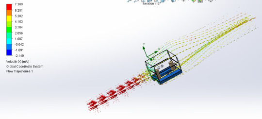
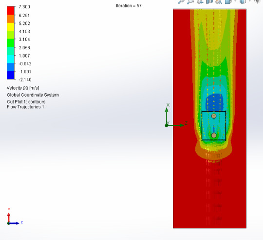
These photos are from the air flow simulation I did yesterday, to find out what impact the wind would have on the structure of the identification buoy. I recorded the animations to make it easier to analyze.
It was fun to do this, I discovered that I can make several different types of fluids, which could be useful in future projects. The article is almost ready, along with the boat and buoy codes.
Here are the charts with results generated from Solidworks:

Generally I don't do this, but I'll put the translation of the analysis I put in the article here, maybe it can help someone.
Although it is not common to carry out engineering tests in this specific context, we chose to conduct an analysis dedicated to aerodynamic conditions, aiming to understand the effect of wind on the structural integrity of the buoy. To carry out this study, we used Solidworks, making use of the fluid simulation system incorporated into the program.
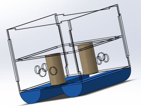
Initially, we modeled the buoy structure, assigning specific materials to each component. Subsequently, we establish the necessary boundary conditions to faithfully simulate the behavior of the structure in real conditions. In the next step, we created surfaces that represent the wind pressure in the region where it impacts the buoy, and defined the area in which the wind pressure would be applied. The application of wind loads and adjustment of analysis settings were carried out using the “Flow Simulation” tool.
This process allowed an accurate representation of the aerodynamic conditions on the buoy structure. Additionally, we adjust relevant parameters for the analysis, ensuring a comprehensive approach.
The simulation execution culminated in the generation of a comprehensive report, documenting the results obtained. The interpretation of these results provided valuable insights into the structure's performance under simulated aerodynamic conditions. This engineering test highlighted the importance of considering aerodynamic conditions when assessing structural integrity.
It is possible to highlight some fundamental reasons for the importance of this analysis, such as the assessment of structural integrity, assessment of operational safety, design optimization, which can result in savings in materials and manufacturing costs.
The Montagem_boia.SLDSAM model was configured with standard parameters, carrying out 57 iterations to achieve convergent results. The mesh was defined with basic dimensions (Nx = 40, Ny = 9, Nz = 17), and boundary conditions were established to represent the fluid environment of interest.
The physical time interval considered was 0 seconds, and the CPU time required for the simulation was also recorded. The simulation results revealed an interesting distribution of fluid properties and flow characteristics. The total number of cells in the mesh was 7626, all occupied by the fluid. Among these, 1106 cells were in direct contact with solids.
The mesh dimensions (X,Y,Z) indicated a significant extension of the model, with minimum and maximum variations in each direction. Analysis of the velocity field revealed a range of [0 m/s; 7,510 m/s], indicating different flow regimes within the simulation domain. The pressure varied between [101294.37 Pa; 101430.23 Pa], with a reference pressure of 101325.00 Pa. The temperature remained relatively constant, with values varying from [293.20 K; 293.21 K]. The fluid density showed a minimum variation, within the range of [1.20 kg/m^3; 1.21 kg/m^3].
There was no consideration of factors such as heat in solids, radiation, porous media and gravity to simplify the model to meet the specific objectives of this simulation. Based on the analysis of the images obtained, the reduction in wind speed becomes visible when facing the structure of the identifying buoy.
Notably, the average wind speed in São Paulo, situated at 25km/h, is insufficient to cause damage to the aforementioned structure or to displace it from its original position. It is also worth noting that, when encountering the obstacle represented by the buoy, the wind flow tends to bypass the structure mostly from above, to the detriment of the sides.
This observation suggests an effective resistance of the buoy to direct wind impact, contributing to its stability and structural robustness. The results clearly indicate that the structure's resistance to wind action is remarkable, since the force exerted by the wind did not reach levels that would compromise the integrity or stability of the configuration.
The solidity of the structure in the face of these conditions suggests that the design presents a robust and adequate response to the expected wind loads.
Sorry for any grammatical errors ~
#stem#studyblr#stem academia#studyspo#study motivation#studyinspo#study aesthetic#engineering#studying#solidworks#3d model#computer engineering#mathematics#flow simulation#cad
17 notes
·
View notes
Video
youtube
Aselsan Sivas HoloBright Nişangah - Sight
My Animation Video: https://youtu.be/f18PF7QY_I8 You can download my All 3D models from here: https://grabcad.com/ozcan.ozaltin-2/projects Also you can see my other renders and animations from here: https://www.artstation.com/ozcan36 You can watch my other videos here: https://www.youtube.com/channel/UCfX6oXfpdhjKL5jaK1aRMKA/featured my mail adress: [email protected] or [email protected] Bütün 3B Modellerimi bu adresden indirebilirsiniz: https://grabcad.com/ozcan.ozaltin-2/projects Ayrıca diğer renderleri ve animasyonları burdan görebilirsiniz: https://www.artstation.com/ozcan36 Diğer videolarımı buradan izleyebilirsiniz: https://www.youtube.com/channel/UCfX6oXfpdhjKL5jaK1aRMKA/featured Mail Adreslerim: [email protected] veya [email protected]
#Tumblr#artists on tumblr#Sight#HoloBright#render#art#sanat#çizim#çizimlerim#model#3D#3D model#blender#animation#solidworks#özcan özaltın#Aselsan#aselsan sivas#roketsan#tai#tusaş#draw#drawing#my art#my post#my draws
2 notes
·
View notes
Text
In my quest to make a set of Star Trek TOS engineering tools into designs that look like actual tools:
The Sonic Wrench! Figured it looked enough like a hook spanner for it to work.


Originally I tried to make the Sonic Wrench a print-in-place but it just stuck together, so I had to separate out the arms from the main body.
Now that it’s separate, it finally works!


I have yet to add the lines on the handle from the original prop, but I’ll do that with the next iteration of the model tomorrow.
#Star Trek tos#Star Trek#montgomery scott#<- the end goal is a Scotty cosplay.#3d model#bones prints things#after finally having certifications in AutoCAD and SolidWorks for a year I finally get an excuse to do Ultra Mega Nerd Shit#like this.#if anyone wants the stl. uhhh. dm me ig? I’ll set up a thingiverse account or smth later once I figure out a good platform to upload-#my models to
3 notes
·
View notes
Text
Discover how SOLIDWORKS 3D CAD, offered by MSD Facilitators, transforms product design with powerful tools for 3D modeling, assembly management, and design validation. Create precise models, streamline collaboration, and accelerate innovation while minimizing costs. Learn why engineers and manufacturers trust SOLIDWORKS 3D CAD for efficient and accurate product development. Unlock the potential of advanced design solutions today!
0 notes
Text
Revit Autodesk Academy, located in Sydney, delivers exceptional training in REVIT, SOLIDWORKS, and AutoCAD.
Revit Autodesk Academy, located in Sydney, delivers exceptional training in REVIT, SOLIDWORKS, and AutoCAD. Our expert-led courses offer hands-on learning experiences, covering fundamentals to advanced levels. Engage in live classes, attain certifications, and undertake practical projects to enhance your design skills. Specializing in Revit and BIM modeling, we prepare you for the forefront of architectural design.
Beyond training, our consultancy services provide personalized solutions for navigating design challenges. Additionally, our architectural staffing solutions optimize workforce management for project excellence. Join us to enhance your design capabilities and thrive in the dynamic realm of design and engineering. Elevate your skills with Revit Autodesk Academy.

#design engineer#course engineering#revit architecture training#solidworks software course#autocad course sydney#drafting online course#cad drafting courses#autocad revit courses#revit course sydney#solidworks training sydney#autocad training sydney#models drawings#3d modeling
1 note
·
View note
Text
Seamlessly Export Your SolidWorks Models to GLTF Format
Are you having difficulty showcasing your SolidWorks model in 3D design to impress your clients with polished and professional 3D presentations? Don't worry, ProtoTech Solutions is here to help you. 🚀
🌐 Presenting your SolidWorks creations in 3D has never been easier. ProtoTech's GLTF Exporter is the key to unlocking a world of possibilities for your designs.
💡 Why ProtoTech's GLTF Exporter? ✅ Seamlessly export your SolidWorks models to GLTF format ✅ Preserve intricate details and textures ✅ Showcase your designs in immersive 3D environments ✅ Impress your clients, colleagues, and friends with professional presentations ✅ Elevate your presentations and WOW your audience
Ready to revolutionize your design presentations? 🚀 Elevate your creations with ProtoTech's GLTF Exporter for SolidWorks.
Get a FREE Trial Today - https://prototechsolutions.com/3d-products/solidworks/gltf-exporter/
#ProtoTech#ProtoTech Solutions#ProtoTech GLTF Exporter#Free Trial#SolidWorks#GLTF Exporter#3D CAD Design#3D Modeling#Design Revolution#Design In 3D#SolidWorks Magic#CAD Plugin Development
0 notes
Video
Exhaust Manifold in Inventor || Inventor Tutorial || Cad Tutorial || 3d ...
#youtube#autodesk inventor drawing tutorial beginner autocad inventor 2022 tutorial autocad 3d mechanical drawing tutorial autodesk inventor 3d model#exhaust#solidworks#inventor
0 notes
Text


Compressed air quick switch DBTF 20i 200 25kV.
WIP.
#kambalka#solidworks#locomotive#wip#isometric#DBTF#switch#25kV#train#reverse engineering#modeling#3d
1 note
·
View note
Text

Design of airpods modelled in SOLIDWORKS & rendered in Keyshot
#3d render#3d model#3d#digital illustration#drawing#keyshot#product design#product development#solidworks
1 note
·
View note
Text
CMM Inspection Services in Gujarat | The SUNCAD Training & Designers

Suncad leading CMM Inspection Services in Gujarat. We Infinity Automation Provide Outdoor as well as indoor CMM inspection services to our valuable customers. CMMs offer a reliable alternative to handheld inspection tools. They monitor the quality of manufactured items to ensure that they match original design plans within the customer’s preferred tolerance levels. CMMs can measure objects at different stages of production to quickly catch issues before the project is finished or before large-volume runs are completed, keeping the production process fast and efficient with less material waste. Under the efficient supervision of our skilled professionals, we have been able to render premium quality gamut of Faro CMM Inspection Service.
The Suncad Training & Designers provides the best CMM Inspection Services in Gujarat. For more information visit on : https://suncad.in/product/cmm-inspection/ or call us on : 9925023229
#BIM modeling and scanning service in Gujarat#3D Scanning in Gujarat#Leica RTC 360 Scanning Service Provider in Gujarat#Heritage scanning services in Gujarat#Faro Scanner Service Provider in Gujarat#3D Plant / refinery scanning service in Gujarat#D Lidar scanning / 3d Terrestrial scanning services in Gujarat#Laser tracker service in Gujarat#Reverse Engineering in Gujarat#3D Inspection services in Gujarat#CMM inspection services in Gujarat#CNC / VMC Machine operating in Gujarat#3D printing Services in Gujarat#Solid Edge training in Gujarat#SolidWorks Training in Gujarat
0 notes
Text
Revolutionize Product Design with SOLIDWORKS 3D CAD
SOLIDWORKS 3D CAD, provided by MSD Facilitators, is an innovative design solution that empowers engineers, designers, and manufacturers to bring their ideas to life with precision and efficiency. With tools tailored for 3D part modeling, assembly creation, and detailed 2D drawings, it enhances every stage of product development.
Key Features of SOLIDWORKS 3D CAD:
3D Modeling Excellence: Create highly detailed designs with parametric and direct modeling techniques.
Assembly Management: Build complex assemblies with interference detection and motion simulation tools.
2D Drawings: Generate precise, professional drawings directly from 3D models.
Simulation and Validation: Perform stress analysis, thermal studies, and motion simulations to ensure your designs meet real-world requirements.
Design Collaboration: Streamlined collaboration tools, including integration with SOLIDWORKS PDM, for improved teamwork.
Why Choose SOLIDWORKS 3D CAD?
Efficiency and Accuracy: The intuitive interface and robust tools reduce design errors and speed up development.
Comprehensive Solution: From concept to production, SOLIDWORKS 3D CAD offers tools for every design phase.
Cost Savings: Minimize prototyping costs and optimize material usage through accurate simulations.
SOLIDWORKS 3D CAD is a game-changer for industries like manufacturing, consumer products, and engineering. It bridges creativity and functionality, enabling businesses to innovate faster while maintaining high-quality standards. Explore the endless possibilities of SOLIDWORKS 3D CAD with expert support from MSD Facilitators.
0 notes
Text
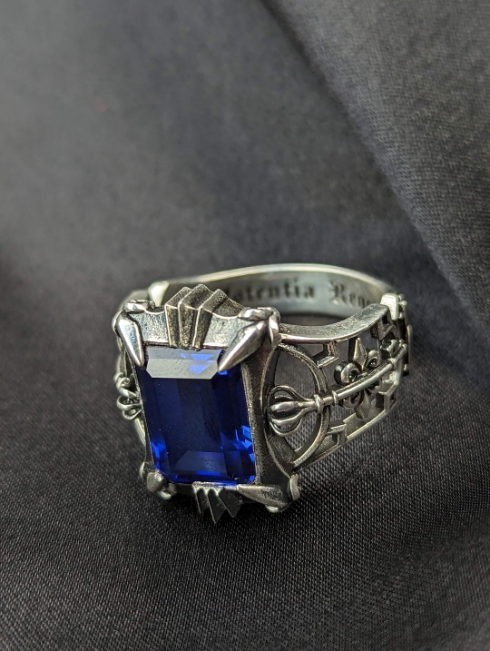
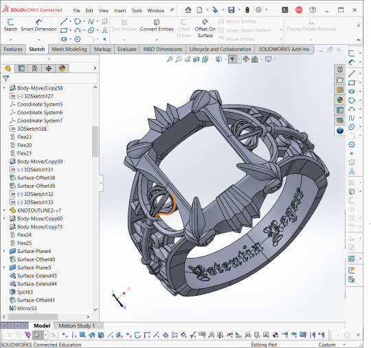
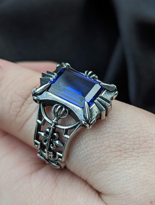
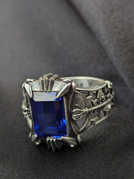

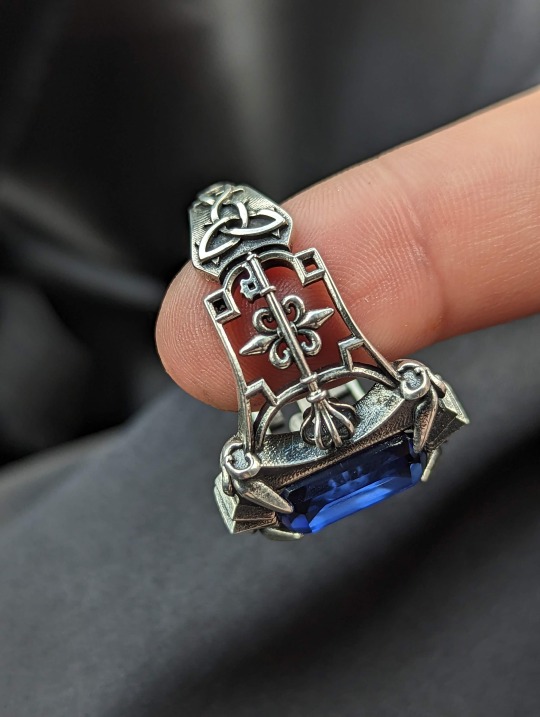
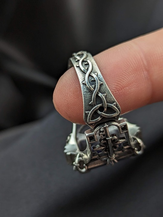
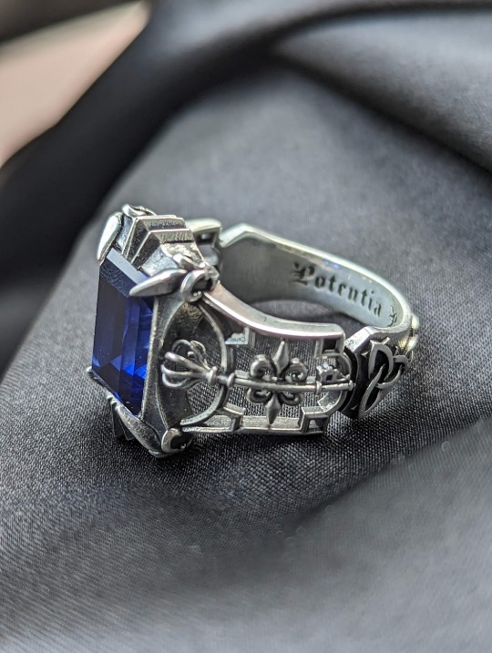
The Phantomhive Ring Nonofficial merchandise, fanmade, custom. ·3D modeled in SolidWorks by @noirserviteur ·3D printed using resin, then cast in sterling silver ·Fitted with blue sapphire (+ diamond chips, soon)
#Kuroshitsuji#Black butler#ciel phantomhive#Our!Ciel#Ring#I would be very remiss not to make a post about this#I did not believe that this would turn out as beautifully as it did#I also did not believe it could be modeled in the first place this well and even if it could be done#That it would not turn out once it came time to be printed and then cast#But I was wrong multiple times#I also hope someone takes a look at the amount of files and can comprehend the amount of time and effort that went into this#When it got here I just stared at it with my mouth open in disbelief for like 2 hours...#edit because tumblr messed up my post#The little diamond chips will see this to completion but I couldn't wait also I don't even think they're super necessary#They're on the way but international shipping is slow as molasses right now#and unpredictable#anyway-#edit 2 added two more pictures so ppl can see the custom knots and adjustment I asked for#💙
1K notes
·
View notes
Note
Are there any primitives or operations you wished parametric CAD software had?
This is tricky, because parametric CAD is what I learned to design on so its feature set feels "natural".
I don't really think so! Most of the obvious innovations are already covered, SolidWorks can take a model back and forth between parametric and primitives modelling in its own weird way, Inventor has really great design for manufacture features, from what I've seen SolidEdge has done some clever stuff with the solver to help you design parts that are customizable as you go down the chain. Who knows what's going on in NX these days, not me. There's definitely some holes in the sense of individual packages lacking features, but almost anything you can ask has been implemented somewhere, by someone.
Good quality design for manufacture tools really do help, I remember doing sheet metal stuff in Inventor back before they cut off free Inventor access and being able to see your generated sheet and bend allowances so clearly was great, and now even OnShape has pretty solid design helpers.
A thing small shops and hobbyists would probably like is better handling of point clouds and photogrammetry for matching parts, since you're much more likely to be working with parts and projects where you didn't do all the design, I've spent many hours trying to accurately model a mating feature, but even that's like. Pretty good these days, importing 3D scans into an editor is pretty standard and the good CAD packages will even let you pick up holes and clean up point clouds directly from the scan.
I'm not that much of a mech eng, and never really was, my CAD is mostly self taught for simple tasks, real mechanical designers no doubt have better opinions on this, @literallymechanical probably has thoughts on T-splines.
38 notes
·
View notes
Text
one of these days im going to release my tlm drafting headcanons from my notes app purgatory and that day is Today.
HERE'S HOW I THINK LEGO MOVIE CHARACTERS WOULD PREPARE AND MAKE DRAFTS
...under the cut
Batman
• Fairly good at drawing. Somehow able to draw straight lines without a ruler perfectly fine every single time but otherwise nothing super noteworthy (he does brag about this constantly however)
• Drafts in white and yellow posca pen??? will use white colored pencil for finer detail however, specifically one of those mechanical colored pencils
• Drafts on black paper because he thinks it makes his designs cooler (it doesn't)
• Dimensions in imperial and would be annoyed if you dare even *insinuate* he use metric. no justification here
• Doodles around his drafts, specifically likes to doodle bats and himself because he, once again, thanks it makes his drafts cooler (the bats kinda do)
• Refuses to leave notes on his designs. you either know what to do or you don't
• Does however write his drawing title obnoxiously large
• Used autocad for like a day, hated it, switched to solidworks and never went back
• Buys autodesk licenses for the rest of the masterbuilders. unwillingly, mind you, wyldstyle just knows his credit card information and abuses it
Benny
• Good at drawing exclusively spaceships. big shock i know
• The king of eyeballing a line or an angle and then labelling it however the fuck he wants. proper measurements take time he could spend drafting or making more spaceships, he'll save measuring and straightedges for drafts he deems important enough
• Uses blueprinting paper. there's no practical purpose for this, he just digs it
• Drafts with whatever writing utensil is on hand
• He gets inspired quite often so he usually keeps a drafting notepad on him just in case
• Leaves a *lot* of notes. Most of them are completely unnecessary and are a funny contrast to his haphazard dimensioning
• Pretty dang good at autocad! Usually reserves it for projects that require a lot more collaboration however
• Usually drafts in metric, can dimension in imperial but prefers not to
• 100% sets autocad to the light background like a monster
• Do not give him any 3d modelling software, he might blow up the computer
Emmet
• Either really good or really bad at drawings (obvs leaning towards bad. we remember the break in plans)
• Dimensions in imperial. I cant justify this one he just does. god bless america or something idk
• Owns a couple drafting pencils but rarely uses them, most of the time he drafts in marker or pen much to the chagrin of anyone who needs to read his drafts (or delight if you're unikitty)
• Started learning how to use autocad after taco tuesday and he's actually pretty good at it! he does use an architectural dimstyle for everything though which is particularly annoying when he's quite often not drafting buildings now
• Has labelled and colored layers 👍 enough said
• Uses disgustingly thick lineweights. horrible.
• Rarely if ever 3d models so he's not good at it, he mostly works on things that 2d conveys better anyways
• Although he's not the best drafter of the master builders, his construction background makes him the best at reading drafts, give him a unikitty draft and he can decipher it like it's nothing
Metalbeard
• Probably the best at drafting of the master builders, he's got the age advantage and lots of practice from making ships
• Drafts in pencil, quill, or charcoal depending
• Who needs straightedges or angle stencils when youre basically a pirate cyborg, expect robot like precision
• Doesn't use standard measuring conventions, instead opts to use the dumbest things possible. The Sea cow's units of measurement were seagulls. It isnt that he cant do normal units of measurement, he just prefers his made up ones
• Makes his drafting paper by himself
• Pretty good with 2d and 3d modelling surprisingly. He doesn't like either, however, he much prefers drafting on paper
• Leaves an average amount of notes on his drafts but has the most disgustingly fancy cursive and writes in his piratey english. Often a nightmare to read if you aren't used to his writing
• Will sometimes do blueprint swaps with Benny wherein they critique each other's work. not sure when they started doing it, but it's become a weekly activity for them
Unikitty
• Worst drafter of the main masterbuilder crew. Most people think it's because she's a cat but no she just doesnt take drafting seriously in the slightest
• Drafts like she's making an arts and crafts project. She has put several bottles of glitter on singular drafts and she will do it again
• Dimensions in rainbows, no knows what this means other than emmet
• Gives the longest, most complicated titles possible
• No such thing as straight lines
• Is entirely capable of drafting properly, just refuses to
• Leaves notes that are entirely unrelated to the draft. she wont tell you how youre supposed to connect two objects but she *will* tell you about the sandwich she ate while making the draft
• Doesnt use autocad, looks too boring
• Didnt use any 3d modelling softwares until she realized you can change the appearance of materials. that was a game changer. still much prefers drafting on paper though
• Likes drafting with emmet sometimes since he seems to be the only person who understands her drawings. to this day no one understands how he does it
Vitruvius
• Going blind has, surprisingly, not made him much worse at drafting, just changed his process a bit
• Drafts in pencil
• Probably the person who least frequently drafts of the main masterbuilders. On account of just not needing to and also on account of being dead
• Dimensions in the old anglo-saxon units of measurement
• Doesn't title his drafts and doesnt see a point in doing so
• Leaves the most vague, utterly confusing notes on his drawings. theyre still related to the drawings unlike unikitty's notes, but theyre very odd
• Doesn't use autocad or 3d modelling softwares, partially because he wouldnt really be able to on account of being blind but also partially because he doesn't really know what they are
• There isnt really much to say about his drafting skills he's about as normal of a drafter as a masterbuilder can be
Wyldstyle
• An engineering teacher's dream student. She may not have the amount of experience metalbeard has but she's still very skilled
• Doesn't like drafting on paper and won't if she doesn't have to
• When she does draft on paper she uses a drafting mechanical pencils. she also 100% collects them
• dimensions in metric to exactly 3 decimal places
• leaves very few if any notes (always very concise ones if included)
• has a case of staedtler stencils that she bought 4 years ago and never uses
• picked up a habit of doodling on drafts from batman but will never admit she got the habit from him
• Autocad PRO. Also really damn good at solidworks and fusion. Give this girl a computer and she'll give you a motorcycle assembly within the hour
• Specializes in automotives
• Spends time with Emmet on the weekends teaching him how to use digital drafting softwares (this process was incredibly frusturating at first but gets easier with time)
#this has been rotting in my drafts and i needed to set it free#live laugh love kind of boring headcanons and combining your interests#the lego movie#lego movie
29 notes
·
View notes