#Isolated Voltage Measurement
Explore tagged Tumblr posts
Visit Tumblr Blog
Explore Tumblr blogs with no restrictions, modern design and the best experience.
Last Seen Tumblr Blogs


Fun Fact
The total number of visits Tumblr.com received during January 2021 is 327 million.
Text
Common Electrical Issues That a High-Quality Current Transformer Can Prevent

In today’s fast-paced industrial world, electrical reliability is more crucial than ever. A small error in current measurement can lead to serious system failures, downtime, and costly repairs. This is where high-quality current transformers (CTs) make a huge difference. But what exactly can a superior CT prevent? Let’s dive in.
What Is a Current Transformer?
A current transformer (CT) is an essential device used to measure alternating current (AC) by producing a scaled-down, manageable current for meters, relays, and other instruments. It enables safe monitoring and accurate metering in high-voltage environments, protecting both equipment and personnel.
Common Electrical Problems a High-Quality CT Can Prevent
1. Overloading and Equipment Failure
Problem: Without accurate current measurement, systems can easily become overloaded, causing motors, transformers, and cables to overheat.
How a CT Helps: A precision CT ensures real-time, reliable current monitoring. It detects overcurrent conditions immediately, allowing protective relays to trip and prevent expensive equipment damage.
2. Inaccurate Energy Billing
Problem: Incorrect current readings can lead to wrong billing, causing businesses to either overpay for energy or face disputes with utilities.
How a CT Helps: High-accuracy CTs provide precise energy data for billing and cost allocation, especially critical in commercial complexes, factories, and power plants.
3. Protection Relay Malfunction
Problem: If a CT delivers incorrect signals, protection relays may not operate during faults, leading to extended damage and system blackouts.
How a CT Helps: Reliable CTs ensure protection relays receive the correct fault current levels, enabling fast and accurate circuit isolation.
4. Short Circuits Going Undetected
Problem: A minor fault can escalate into a full-blown short circuit if the protection system doesn’t detect it early.
How a CT Helps: Quality CTs capture even small fault currents, triggering alarms or shutdowns before damage spirals out of control.
5. Phase Imbalance Issues
Problem: Imbalanced phases cause excessive heating, motor inefficiency, and damage to sensitive equipment.
How a CT Helps: High-precision CTs monitor each phase accurately, enabling detection of phase unbalance conditions early and preventing system inefficiencies.
6. Harmonic Distortions and Power Quality Problems
Problem: Harmonic distortions interfere with the performance of sensitive equipment and reduce the overall power quality.
How a CT Helps: Specialized CTs can detect abnormal waveform distortions, enabling corrective action through harmonic filtering or load balancing.
Why Invest in a High-Quality Current Transformer?
Accuracy: Achieve metering-class precision essential for both billing and protection. Durability: Longer lifespan even in harsh industrial environments. Safety: Better insulation, thermal stability, and overload capacity. Compliance: Meets international standards like IEC and ANSI.
How Enza Electric Ensures CT Excellence
At Enza Electric, we specialize in manufacturing current transformers built with precision, reliability, and global standards compliance. Whether you need CTs for commercial metering, industrial protection, or utility-scale power distribution, our solutions guarantee unmatched performance.
Customizable options for various ratings High dielectric strength for safety Long service life even in extreme conditions
Explore our Current Transformer Range
Final Thoughts
A high-quality current transformer isn’t just a tool — it’s a first line of defense for your electrical system. Investing in precision-engineered CTs prevents common electrical issues, boosts system longevity, ensures accurate billing, and improves overall operational safety.
If you’re serious about protecting your infrastructure and optimizing performance, choosing Enza Electric’s current transformers is a smart move.
9 notes
·
View notes
Text
What is the installation space requirement and power consumption?
Planning for both production capacity and practical installation needs—namely, power consumption and floor space—is crucial when thinking about buying a square-bottom paper bag maker. Your factory layout, monthly operating expenses, and long-term scalability are all directly impacted by these two variables.
At Prakash Machineries Pvt. Ltd., we design our square-bottom paper bag machines to be Whether you’re running a large industrial setup or launching a small startup, our machines are built to integrate smoothly into your workspace without demanding major infrastructure upgrades.
In this guide, we explain the power and space requirements of our square-bottom paper bag machines and how you can prepare your facility for successful installation and operation.
⚡ Power Consumption: Designed for Energy Efficiency
Our machine is equipped with servo-driven motors, automated PLC controls, and energy-optimized components to ensure high productivity with minimal energy use. On average, the power consumption of our square-bottom paper bag-making machine falls between
✅ 10 kW to 14 kW per hour
(Depending on the machine model, size range, and optional attachments)
🔋 Breakdown of Power Usage:
Component Approximate Load Main motor (servo drive) 5–7 kW Vacuum pump 2–3 kW Gluing system & heater (if any) 1–2 kW Control panel and sensors 0.5–1 kW Optional attachments (printer, handle unit) 1–2 kW
This efficient power profile means that you won’t need industrial-scale electricity infrastructure to run the machine. Even for startups or medium-scale units, a standard 3-phase connection with a 20–25 HP (horsepower) supply is typically sufficient.
✅ Monthly Cost Estimate:
Assuming 8 hours/day of operation at an average of 12 kW/hr:
12 kW × 8 hours × 30 days = 2,880 kWh/month
At ₹8/kWh (approx. industrial rate in India), monthly electricity cost = ₹23,000
This makes our machine a cost-effective production solution, especially when you compare the high output capacity (up to 192,000 bags/day) with the low operational expense.
📐 Required Space for Installation
Our square-bottom paper bag machines are compact, modular, and engineered to occupy minimal floor space while still offering full production capabilities.
✅ Recommended Installation Area:
20 feet (L) × 8 feet (W) for standard machines 25 feet (L) × 10 feet (W) if optional units (e.g., printer, handle pasting) are included
🏭 Ideal Layout Plan Includes:
Machine footprint—main operational unit
Paper roll loading area—space for jumbo rolls (up to 1 m wide)
Bag collection table—output stacking and packing zone
Operator movement zone—minimum 3 ft clearance on each side
Electrical control cabinet—attached or wall-mounted
Optional space—for printer unit, handle applicator, or lamination feeder (if installed)
Our machines can be installed in a production unit as small as 500–600 sq. ft. You do not need a massive industrial hall. Even a startup with a moderate factory space can begin production seamlessly.
🛠️ Site Preparation Checklist
Before installation, ensure the following infrastructure is in place:
✔️ Electrical Requirements:
3-phase power connection (415V)
A stabilizer or UPS recommended for voltage fluctuation zones
Isolated circuit breaker and control panel for machine safety
✔️ Space & Foundation:
Flat, concrete floor surface (leveling required)
Dust-free, dry environment for optimal performance
Space for operators to safely move around machine
✔️ Ventilation & Safety:
Basic ventilation or exhaust fans (especially in hot climates)
Fire safety measures as per industrial compliance
Proper lighting for operator visibility
💡 Why This Matters to Your Business
Understanding your power and space needs in advance helps you
Avoid delays in installation
Ensure uninterrupted production
Optimize your floor plan for raw material, output, and manpower
Control operational costs with energy-efficient planning
This is especially crucial for startups, small businesses, or factories expanding capacity, where space and energy planning affect both short-term efficiency and long-term profitability.
🔧 Our Support Includes:
At Prakash Machineries Pvt Ltd, we don’t just deliver machines—we offer end-to-end installation support, including:
Pre-installation guidance (electrical, civil layout)
Custom floor plans for your site
On-site machine setup and calibration
Operator training and troubleshooting
Maintenance and after-sales service
🏁 Conclusion: Compact. Efficient. Installation-Ready.
Our square-bottom paper bag-making machines are designed to be energy-efficient and space-friendly—ideal for both high-output factories and compact manufacturing setups. With low power consumption (10–14 kW) and a compact footprint (under 250 sq. ft.), you can begin or scale up your paper bag production with minimal infrastructure investment.
📞 Plan Your Factory Setup With Us
Want help designing your factory layout? Need a customized installation guide for your plant? We’re here to help.
👉 Contact Prakash Machineries Pvt Ltd to get a personalized site layout, electrical requirement checklist, or expert consultation to prepare your facility for high-speed, efficient paper bag production.
#manufacturer#paper bag manufacturer#paper bag#paper#machines#flexo#v bottom#square bottom#alien stage#baking#bags#cake#chris sturniolo#cooking#critical role#dan and phil#delicious#breakfast#chocolate
1 note
·
View note
Text
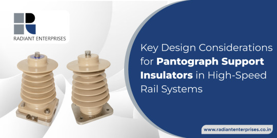
Key Design Considerations for Pantograph Support Insulators in High-Speed Rail Systems
In the realm of high-speed rail systems, every component plays a crucial role in ensuring safe and efficient operations. Among these components, pantograph support insulators stand out as critical elements that facilitate the seamless transmission of power from overhead lines to the train's electrical system. As a leading pantograph insulator manufacturer in India, Radiant Enterprises recognizes the importance of meticulous design considerations in crafting reliable and durable insulators. In this blog post, we'll explore the key design considerations essential for pantograph support insulators in 25 KV high-speed rail systems, shedding light on Radiant Enterprises' commitment to excellence in manufacturing.
Understanding Pantograph Support Insulators
Pantograph support insulators are integral components of the overhead electrification system in high-speed rail networks. These insulators provide electrical isolation and mechanical support for the pantograph, which is the apparatus mounted on the train's roof responsible for collecting electricity from the overhead wires (catenary). In 25 KV high-speed rail systems, where trains operate at exceptionally high speeds, the performance and reliability of pantograph support insulators are paramount.
Design Considerations for Pantograph Support Insulators
Material Selection: The choice of materials significantly influences the performance and longevity of pantograph support insulators. At Radiant Enterprises, we utilize high-quality, durable materials such as silicone rubber or composite polymers that exhibit excellent electrical insulation properties, mechanical strength, and resistance to environmental factors such as UV radiation, pollution, and temperature variations.
2. Electrical Insulation: Ensuring reliable electrical insulation is paramount to prevent electrical arcing and ensure the safe transmission of power. Our pantograph support insulators are engineered to withstand high voltage levels (25 KV) and exhibit low electrical conductivity to minimize power losses and mitigate the risk of electrical faults.
3. Mechanical Strength: Pantograph support insulators are subjected to mechanical stresses induced by the pantograph's movement and external forces such as wind loads and vibrations. Therefore, our insulators undergo rigorous mechanical testing to ensure they can withstand these forces without deformation or failure, ensuring uninterrupted operation and minimal maintenance requirements.
4. Corrosion Resistance: In outdoor environments exposed to moisture, pollution, and corrosive agents, corrosion resistance is essential to maintain the structural integrity of pantograph support insulators over their operational lifespan. Our insulators are engineered with corrosion-resistant materials and undergo surface treatments to enhance their resistance to rust and degradation, ensuring long-term reliability and performance.
5. Dimensional Accuracy: Precision engineering is critical to ensure proper fit and alignment of pantograph support insulators with the overhead wires and the train's pantograph. Our insulators are manufactured with tight tolerances and undergo strict quality control measures to guarantee dimensional accuracy and compatibility with the rail infrastructure, minimizing installation challenges and optimizing performance.
6. UV Stability: Exposure to ultraviolet (UV) radiation can degrade insulator materials over time, compromising their electrical and mechanical properties. Therefore, our pantograph support insulators are formulated with UV-stabilized materials that withstand prolonged exposure to sunlight without degradation, ensuring reliable performance and longevity in outdoor applications.
Radiant Enterprises: Your Trusted Pantograph Insulator Manufacturer in India
As a leading manufacturer of pantograph support insulators in India, Radiant Enterprises is committed to delivering superior quality products that meet the stringent requirements of high-speed rail systems. Our state-of-the-art manufacturing facilities, coupled with a team of experienced engineers and quality assurance experts, enable us to design and produce pantograph insulators that excel in performance, reliability, and durability.
Conclusion
In the dynamic world of high-speed rail systems, the reliability and performance of pantograph support insulators are critical for ensuring safe and efficient operations. By adhering to meticulous design considerations such as material selection, electrical insulation, mechanical strength, corrosion resistance, dimensional accuracy, and UV stability, manufacturers like Radiant Enterprises can deliver pantograph insulators that meet the demanding requirements of 25 KV high-speed rail systems. As a trusted pantograph insulator manufacturer in India, Radiant Enterprises is committed to providing innovative solutions that contribute to the advancement of railway electrification technology and the seamless operation of high-speed rail networks.
#Customised epoxy insulators manufacturer in India#Pantograph insulator manufacturer in India#25 KV pantograph support insulators manufacturers in India#25 KV roof busbar support insulator manufacturers in India#Solid third rail insulator#Customized Powerrail Epoxy Insulators#Epoxy Insulators#Epoxy insulator manufacturers in India
7 notes
·
View notes
Text
Undergrad research blast from the past. Here I am in 2020 assembling a micro fluidic flow cell with a gold electrode block. I think I took this video for myself so I knew what to clip to what. This was when I worked with electrochemical sensors, transducing signals via impedance spectroscopy.
A lot of electrochemical techniques rely on measuring voltages or currents, but in this lab we looked at impedance- which is a fancy combination of regular resistance (like the same one from ohms law) and the imaginary portion of the resistance that arises from the alternating current we supply.
I would functionalize different groups on the gold working electrode by exposing the surface to a solution of thiolated biomarker capture groups. Thiols love to form self-assembled mono layers over gold, so anything tagged with thiol ends up sticking. [Aside: Apparently after I left the group they moved away from gold thiol interactions because they weren't strong enough to modify the electrode surface in a stable and predictable way, especially if we were flowing the solution over the surface (which we wanted to do for various automation reasons)]. The capture groups we used were various modified cyclodextrins- little sugar cups with hydrophobic pockets inside and a hydrophilic exterior. Cyclodextrins are the basis of febreeze- a cyclodextrin spray that captures odor molecules in that hydrophobic pocket so they can't interact with receptors in your nose. We focused on capturing hydrophobic things in our little pocket because many different hydrophobic biomarkers are relevant to many different diseases, but a lot of sensors struggle to interact with them in the aqueous environment of bodily fluids.
My work was two fold:
1) setting up an automated system for greater reproducibility and less human labor. I had to figure out how to get my computer, the potentiostat (which controls the alternating current put in, and reads the working electrode response), the microfluidic pump, and the actuator that switched between samples to all talk to each other so I could set up my solutions, automatically flow the thiol solution for an appropriate time and flow rate to modify the surface, then automatically flow a bio fluid sample (or rather in the beginning, pure samples of specific isolated biomarkers, tho their tendency to aggregate in aqueous solution may have changed the way they would interact with the sensor from how they would in a native environment, stabilized in blood or urine) over the electrode and cue the potentiostat for multiple measurements, and then flow cleaning solutions to clean out the tubings and renew the electrode. This involved transistor level logic (pain) and working with the potentiostat company to interact with their proprietary software language (pain) and so much dicking around with the physical components.
2) coming up with new cyclodextrin variants to test, and optimizing the parameters for surface functionalization. What concentrations and times and flow rates to use? How do different groups around the edge of the cyclodextrin affect the ability to capture distinct classes of neurotransmitters? I wasn't working with specific sensors, I was trying to get cross reactivity for the purpose of constructing nonspecific sensor arrays (less akin to antibody/antigen binding of ELISAs and more like the nonspecific combinatorial assaying you do with receptors in your tongue or nose to identify "taste profiles" or "smell profiles"), so I wanted diverse responses to diverse assortments of molecules.
Idk where I'm going with this. Mostly reminiscing. I don't miss the math or programming or the physical experience of being at the bench (I find chemistry more "fun") but I liked the ultimate goal more. I think cross reactive sensor arrays and principle component analysis could really change how we do biosample testing, and could potentially be useful for defining biochemical subtypes of subjectively defined mental illnesses.... I think that could (maybe, possibly, if things all work and are sufficiently capturing relevant variance in biochemistry from blood or piss or sweat or what have you) be a more useful way to diagnose mental illness and correlate to possible responses to medications than phenotypic analysis/interviews/questionnaires/trial and error pill prescribing.
4 notes
·
View notes
Text
Well, Victor Timely sure knows how to draw attention and eventually make some money. And make me write another post on a partially scientific topic. I’m not an expert tho!


On the right side of the stage there's a sign, 'Electrifying achievement to harness the power of time'
And then he explains what the Loom does. 'My temporal loom inverts the temporal decay of the electricity flowing through it, lowering its entropy and gathering it into fine threads of power. Which it then weaves into elegant ropes of voltage. A chaos of particles is transformed into order.'
(I'm gonna assume he quotes OB's guidebook and not just wings it all randomly, because at least a part of what he says made sense to me)
In short, he says that the Loom can arrange matter into an ordered state. And that it not only uses electricity but also reproduces it in a form of threads and ropes. That would explain how the TVA operates outside of uh time and why it has power surges in s2e1. But it still leaves the question from where comes the initial energy to kick start the loom.
I believe that the temporal decay is synonimous to the increasing entropy. Entropy is a measure of how many ways there are possible to rearrange the same amount of matter without changing its 'shape'. Simply put, objects with low entropy can't be rearranged without being broken/reassembled. And those with high entropy can be rearranged without changing its form or shape, so to speak. Prof. Brian Cox compares the former with a sand castle and the latter with a pile of sand 👌 Another important point is that entropy inevitably increases over time: order becomes disorder. BUT. If we go back in time — and not like in Doctor who but like in Tenet — then we would observe entropy again, increasing relative to us (and not decreasing if we observe it from the present into the past).
Now, I think that raw time, as OB named it, is energy with high entropy and a physical timeline is rearranged energy with low entropy. When a timeline branches, entropy increases again. Also, temporal radiation means a form of energy that travels from a source through space.
(Side note. My initial guess was: to isolate a timeline HWR would need to have something threaded. Which would mean that the Loom came first. But when the timeline branches it creates more input INTO the Loom. And what’s more, in the end of s1 the Sacred timeline branches into a web which resembles the raw time. Just like Timely said, ‘the energy of the past, present and future flows all around us.’ And HWR managed to harness it to sustain his big project. So, raw time/sacred/other timelines exist as they are, and the Loom is just a tool to operate the former)
(Side note 2. The Sacred timeline doesn’t consist of just one universe. It’s weaved from multiple but strictly selected multiversal timelines. Otherwise we’d see minutemen in previous movies)
I can accept temporal auras which can help track and pull someone across space-time. Or temporal radiation, which is itself a fun concept. But what puzzles me the most is time being a form of matter. In our reality, at least according to the current physics, it’s a dimension. I can’t wrap my head around it. Even in a fictional way, i can’t explain it to myself. Because I experience time the same way people do in the show. I think here Timely either simplifies so to make people understand and buy his Loom or he doesn’t know what he’s talking about.
And that’s why, until proven otherwise or explained by OB, I think that the Loom is first of all just a big power generator. The timelines are being pruned manually by time cops setting time bombs and arresting variants. Resetting a timeline means removing entropy that was created by a variant’s actions. The Loom generates energy for the TVA, people working there and their equipment. And maybe it charges Kang’s time chair.
The multiverse doesn’t need the Loom to function. Time flows on its own, entropy increases all the time, it’s far more inevitable than Thanos. Loom is a tool, it can be removed, repaired or upscaled. The TVA as organisation and people and city (?) all need it but, most of all, the person behind it.

#loki series#loki season 2#loki spoilers#kang the conqueror#victor timely#he who remains#loki meta#LWR's theories
15 notes
·
View notes
Text
When P-channel meets N-channel in push-pull: The wild battle between bootstrap drivers and body diodes 🔥
Ever swapped out a BJT push-pull with MOSFETs, only to watch your output voltage get cut in half? Ouch. We’ve all been there—and turns out, the culprit is usually the driver circuit. Let’s dive into why MOSFET push-pull designs feel like walking a tightrope, and how to nail the balance.
Why is driver design make-or-break for P-channel + N-channel push-pull?

Here’s the drama: MOSFETs need a gate-source voltage (Vgs) above their threshold to turn on. But for the top P-channel MOSFET? Its source is tied to the positive supply. So if you’re working with 12V, that P-channel MOSFET might need a gate voltage lower than the source (like -10V) to switch on—and regular driver chips can’t spit out negative voltages. Total facepalm moment.
Cue the hero: bootstrap drivers. This “floating power” trick uses a capacitor to store energy, and it’s genius:
Charging phase: When the bottom N-channel MOSFET is on, the boot capacitor charges up via a diode, soaking up 12V.
Discharging phase: When the top P-channel MOSFET needs to switch on, that capacitor “floats” above the output voltage. Suddenly, the gate voltage = output voltage + 12V—more than enough to hit that Vgs threshold. Problem solved? Almost.

The bootstrap puzzle: Capacitors, diodes, and resistors that make or break it
Bootstrap circuits aren’t set-it-and-forget-it. Mess up the components, and you’ll get oscillation, overheating, or worse.
Boot capacitor (Cboot): Your energy bank. It needs enough juice to handle the gate charge (Qg) without dropping too much voltage (ΔVboot). Rule of thumb: Cboot ≥ Qg / ΔVboot. For a 200kHz circuit with Qg=20nC and ΔVboot=1V, that’s at least 20nF—but most folks use 100nF to 1μF (X7R ceramics work best). And don’t skimp on voltage rating—go 20% above your supply (12V? 16V cap is safe).
Boot diode (Dboot): Speed demon required. Slow reverse recovery times (over 50ns) cause wild current spikes at high frequencies—we’re talking 3x normal current. Snag a fast-recovery or Schottky diode (under 0.5V forward drop) to keep losses low.
Boot resistor (Rboot): The chaos tamer. 10-47Ω balances charging speed and EMI. We’ve seen 22Ω cut ringing from 3V to 0.8V in 100kHz circuits. Small, but mighty.
The body diode: The silent killer in 续流 (freewheeling)
Here’s where things get sneaky: MOSFETs have built-in body diodes that kick in during freewheeling. But they’re troublemakers:
Voltage drop: 0.7-1V might not sound bad, but at 10A? That’s 10W wasted—knocking efficiency down by 5%.
Reverse recovery: Stored charge in the PN junction causes massive current spikes. In 500kHz circuits, we’ve measured spikes 3x the normal current—hello, EMI failures.
Fixes that actually work:
Synchronous rectification: Use the bottom MOSFET to “override” the body diode. Drops voltage to under 0.1V—cuts losses by 90%.
Soft-recovery MOSFETs: Look for ones with 70% less reverse recovery charge (Qrr) than standard parts. Game-changer for light loads.
RC snubbers: A 100Ω + 0.1μF across drain-source soaks up spikes—we’ve seen EMI drop 20dBμV.

Real talk: From 85% to 94% efficiency—how we fixed a push-pull
A buddy swapped a 12V→5V BJT push-pull to MOSFETs. Before: 5A output, 85% efficiency, 75°C temps. After adding a bootstrap driver and better MOSFETs? 94% efficiency, 45°C. But the body diode still dragged down light-load efficiency—until we added synchronous rectification. Now it’s 92% even at low loads. Chef’s kiss.
Quick PCB hacks to avoid facepalms
Keep bootstrap components (Cboot, Dboot, Rboot) within 1cm of the driver IC—10nH of parasitic inductance can drop your gate voltage by 0.5V.
Isolate gate traces with shielding or differential pairs—cross-talk once added 20ns delay and killed 1.2% efficiency.
Heat management matters: Low thermal resistance packages cut heatsink size by 50%.
So—who’s struggled with MOSFET push-pull circuits? Did your voltage tank? Fight with body diodes? Drop your war stories in the comments—let’s troubleshoot together! 💬
(No brands, just battle-tested tips. Share if you’ve been there.)
0 notes
Text
Comprehensive Electrical Safety Standards for Utility-Scale Solar Farms

Australia’s growing network of utility-scale solar farms is reshaping the nation’s energy landscape. While conversations often centre on output and cost, the foundation of every reliable solar project is strong compliance with electrical regulations. Meeting these requirements goes beyond checking boxes. It helps prevent hazards and supports smooth operations over the long term.
This article explores the core safety standards that guide solar developments, from smart system planning to risk management during construction. You’ll also learn how engineers, project managers, and consultants work together to ensure each installation meets safety protocols and performs reliably well into the future.
Standard Practices in Solar Design and Planning
Designing a solar farm involves proper planning to safeguard safety, compliance, and long-term viability. Here's how solar farms are planned the right way from the start:
Design With Safety as a Foundation
Safety in utility-scale solar farms begins with smart planning. At the concept design stage, it’s important to consider electrical regulations in every part of the project. This includes leaving enough space between components for safe access, choosing the right cable sizes to avoid overheating, and using thermal zoning to reduce the risk of equipment failure.
In standard industry practice, concept design should also consider the accessibility of future maintenance to accommodate the system's lifecycle, from daily operations to fault isolation and system upgrades.
The Role of Engineering Firms and Electrical Consultants
Engineering firms and consultants carry out detailed studies like load flow analysis, protection coordination, and fault-level checks that inform the physical layout of components and safety thresholds of equipment.
Consultants ensure that designs meet electrical regulations like AS/NZS 3000 Wiring Rules and grid connection codes specific to DNSPs. Meanwhile, engineering firms are responsible for detailed frameworks and specifications that can be safely implemented by on-site teams.
Safety Measures in Electrical Planning
A well-engineered electrical plan is more than a schematic requirement, it is a form of safety document. This paperwork entails the following:
Clear single-line diagrams (SLDs) showing breakers, fuses, isolators, and connections
Voltage drop calculations to ensure stable power and prevent overheating
Surge protection planning to guard against lightning and switching surges; and
A solid earthing design to prevent electric shock hazards
Incorporating these preventative safety elements into the planning phase reduces the need for rework, ensures code compliance, and protects infrastructure and human life.
Safety Measures During Construction and Operation
Safety is a non-negotiable factor, especially during construction and operation, where accidents are prone to happen. Below are the key safety practices that should be integrated during construction and operational phases:
Site Management
Once the design is approved, the focus shifts to construction. Site management teams are responsible for ensuring the project is built without compromising safety. These duties include daily safety briefings, SWMS enforcement, PPE compliance, and securing high-voltage areas with proper signage and barriers. Additionally, managers are responsible for coordinating with subcontractors and inspectors to ensure the safety of the project.
Critical Safety Procedures for Active Work Zones
Live component installation requires additional oversight as hazards can potentially happen. Enforcing safety measures such as lock-out/tag-out procedures, live voltage testing, and temporary isolation boards helps control and manage safety during staged energisation.
Other on-site electrical safety practices at this stage also include:
Continuity and insulation resistance testing before connecting circuits.
Protective earth verification for metal structures and enclosures.
Use of thermal imaging to identify hotspots before commissioning.
These practices are mandated under electrical regulations, and failure to follow them can delay projects or lead to serious incidents.
Commissioning and Final Compliance Testing
A series of rigorous electrical tests before a solar farm can operate. These procedures involve polarity and impedance checks, earth fault loop impedance testing, and final inspections done by electrical consultants to validate alignment with Australian standards and grid connection requirements. This final test is a crucial opportunity to identify and resolve any latent risks.
Ensure Solar Safety with ElectraGlobe
Safety in utility-scale solar farms relies on strict adherence to Australian electrical regulations and consistently applied safety practices. Each phase, from planning to final commissioning, should be carried out with accuracy, attention to detail, and accountability. When safety is overlooked, project risks can increase, leading to delays, higher costs, and potential harm to personnel.
With ElectraGlobe, safety is integrated into every stage of solar development. Our experts provide complete support from concept design to on-site execution to ensure your project stays safe, compliant, and on track. Learn more about our services at our website today!
0 notes
Text
What Are Current Sense Transformers?
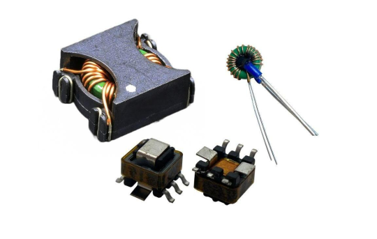
A Current Sense Transformer is an electronic component that measures current based on magnetic induction. It typically consists of a primary winding (or conductor) and one or more secondary windings. When current flows through the primary conductor, it generates a magnetic field, which induces a proportional voltage or current in the secondary winding—enabling isolated, non-contact current sensing.
Get more details: What Are Current Sense Transformers?
#electronics#integrated circuits#semiconductor#components#electronic#module#chips#electronic devices#manufacturing#transformers
1 note
·
View note
Text
circuit boards repair
🛠️ Precision Restored: Your Complete Guide to Network Analyzer & Spectrum Analyzer Repair
In the ever-evolving world of RF and electronic testing, maintaining high-performance instruments is not just important—it's essential. From network analyzers to spectrum analyzers, even minor calibration or circuit board issues can affect the accuracy of your test results. That’s where Restorerf.com comes in—your trusted partner for expert RF test equipment repair and calibration services.
Let’s explore how timely repair of your advanced instruments can save both time and cost, while improving lab efficiency 🔧📡
📡 Why Network Analyzer Repair Is Crucial for High-Performance Testing
A Network Analyzer repair service plays a pivotal role in maintaining signal integrity and device performance. These analyzers measure parameters like return loss, insertion loss, S-parameters, and more. A faulty analyzer can lead to poor diagnostics, invalid test results, and delays in development cycles.
At Restorerf.com, our engineers are trained in handling RF and microwave systems with extreme precision. Whether it's an Agilent, Keysight, or Rohde & Schwarz model, we can restore your device to peak condition—ensuring accuracy and repeatability every time.
📶 When to Consider Repairing Your Spectrum Analyzer RF Equipment
Your Spectrum analyzer RF equipment is your eyes into the frequency domain. If it starts producing erratic noise floors, incorrect amplitude readings, or unstable frequency sweeps, it's time to consider professional servicing.
Restorerf.com specializes in diagnosing and repairing all RF spectrum analyzers including Rohde & Schwarz, Tektronix, Anritsu, and more. With years of experience and state-of-the-art calibration tools, we ensure that your analyzer delivers the precision you rely on.
A high-functioning spectrum analyzer ensures seamless testing of wireless communication, EMI troubleshooting, and signal strength measurements 📈📲
🧩 Circuit Boards Repair: The Heart of Every Instrument
Whether in a signal generator, oscilloscope, or analyzer, circuit boards repair is vital to maintain device functionality. A single defective component—like a capacitor or voltage regulator—can cause your entire equipment to fail or produce inaccurate readings.
Restorerf.com offers expert-level PCB repair services, including reflow soldering, chip replacement, connector rework, and more. We don’t just fix—we troubleshoot and optimize for performance, offering long-term reliability.
Say goodbye to recurring faults and say hello to restored electronics 🚀🖥️
🔧 Restore Accuracy With Expert Repair Spectrum Analyzer Services
At Restorerf.com, Repair Spectrum Analyzer services include everything from fault isolation to full system recalibration. Our diagnostic approach goes beyond surface-level issues—we examine the input attenuators, IF stages, display systems, and control boards to ensure full-spectrum recovery.
You’ll get:
✅ Full calibration traceable to international standards ✅ Component-level repair ✅ Firmware updates and alignment ✅ Rapid turnaround times
Trust Restorerf.com to restore accuracy and extend the life of your spectrum analyzer 🔬⚙️
🧪 Why Fluke Repair Is More Than Just Maintenance
Fluke repair services at Restorerf.com cover popular models like Fluke multimeters, BERT testers, and digital scopemeters. These instruments are known for their ruggedness and reliability—but like all electronics, they can wear down over time.
From cracked screens and damaged probes to calibration errors, our technicians perform deep-dive diagnostics and full refurbishments. We understand the value of precision in electrical measurement—and we bring your Fluke back to its factory-grade performance 🧲🔍
⚡ Why Choose Restorerf.com?
Here’s why hundreds of electronics labs, universities, and defense contractors rely on Restorerf.com for their RF test equipment repair needs:
💼 Certified Technicians: Our engineers have manufacturer training and experience. 📏 Precision Tools: We use advanced calibration equipment and software. 📦 Secure Shipping & Handling: We protect your instruments like our own. 🔁 Quick Turnaround: Most repairs are completed within 5–7 business days. 💡 Transparency: Free diagnostics and no surprise fees.
🛡️ Preventive Maintenance Tips for RF Test Equipment
While repair services are essential, preventive care can go a long way in extending your device’s lifespan. Here are a few maintenance tips:
Clean ports and connectors regularly using isopropyl alcohol and lint-free swabs
Store your equipment in dry, dust-free environments
Update firmware whenever possible
Schedule periodic calibration
Use proper grounding during testing
Implementing these simple habits can reduce downtime and preserve your instruments’ precision 💡🧼
0 notes
Text
Automotive Isolated Amplifier Market: CAGR, Revenue, and Market Share by Segment 2025–2032

MARKET INSIGHTS
The global Automotive Isolated Amplifier Market size was valued at US$ 345.6 million in 2024 and is projected to reach US$ 567.8 million by 2032, at a CAGR of 6.4% during the forecast period 2025-2032. This growth trajectory aligns with increasing vehicle electrification trends, where isolated amplifiers play a critical role in noise-sensitive automotive applications.
Automotive isolated amplifiers are specialized electronic components designed to amplify low-level signals while preventing ground loops and protecting sensitive circuits from high-voltage transients. These devices find extensive application in electric vehicles (EVs), hybrid vehicles, and automotive battery management systems. Key variants include optoelectronic isolated amplifiers, capacitor isolated amplifiers, and transformer isolated amplifiers, each offering distinct advantages in terms of isolation voltage and signal integrity.
The market expansion is driven by several critical factors: the global push towards vehicle electrification, stringent automotive safety regulations, and growing demand for advanced driver-assistance systems (ADAS). Asia-Pacific currently dominates the market, accounting for 48% of global demand in 2024, primarily due to China's leadership in EV production. Major players like ADI, TI, and ROHM are actively developing next-generation isolated amplifiers with higher integration and improved electromagnetic compatibility to meet evolving automotive requirements.
MARKET DYNAMICS
MARKET DRIVERS
Accelerating Shift Towards Electric and Hybrid Vehicles Fuels Demand for Isolated Amplifiers
The global automotive industry is undergoing a transformative shift towards electric vehicles (EVs) and hybrid electric vehicles (HEVs), creating substantial demand for advanced electronic components including isolated amplifiers. With over 10 million EVs sold worldwide in 2022, representing a 55% increase from the previous year, vehicle electrification has become a key driver for isolated amplifier adoption. These components play a critical role in battery management systems, motor control circuits, and charging infrastructure, ensuring safe voltage measurement and signal isolation in high-voltage environments. As governments implement stricter emission regulations and consumers embrace sustainable transportation, the market for automotive isolated amplifiers is projected to grow in tandem with EV adoption rates.
Increasing Vehicle Electrification and Advanced Driver Assistance Systems (ADAS) Adoption
The proliferation of ADAS features in modern vehicles, ranging from basic collision warning systems to fully autonomous driving capabilities, is significantly contributing to market expansion. Isolated amplifiers are essential components in these systems, providing reliable signal conditioning and noise isolation for critical safety applications. With over 85% of new vehicles now equipped with at least one ADAS feature, and major automotive markets mandating certain safety technologies, the demand for high-performance isolated amplifiers continues to rise. The integration of radar, lidar, and camera systems in vehicles creates multiple application points where precision signal amplification with electrical isolation is required for optimal performance and safety compliance.
Stringent Automotive Safety Standards and Regulatory Requirements
Global automotive safety standards and electromagnetic compatibility (EMC) regulations are becoming increasingly rigorous, driving the need for reliable isolated amplification solutions. These components help automotive systems meet critical isolation requirements while maintaining signal integrity in electrically noisy environments. The implementation of automotive functional safety standards such as ISO 26262 has led to greater adoption of isolated amplifiers in safety-critical applications including braking systems, power steering, and battery management. With automotive manufacturers facing stricter homologation requirements worldwide, the market for certified isolated amplifier solutions is experiencing sustained growth across all vehicle segments.
MARKET RESTRAINTS
Complex Integration Challenges in Automotive Electronics Design
The increasing complexity of automotive electronic systems presents significant integration challenges for isolated amplifier solutions. Modern vehicles may contain over 100 electronic control units (ECUs), creating highly congested electrical environments where signal integrity must be meticulously maintained. Isolated amplifiers must accommodate shrinking form factors while delivering higher performance, creating engineering challenges in thermal management, power efficiency, and noise immunity. These technical hurdles can prolong development cycles and increase implementation costs, particularly for advanced applications in autonomous driving systems and high-voltage powertrains.
Supply Chain Disruptions and Semiconductor Shortages
The automotive industry continues to face supply chain vulnerabilities that impact the availability of critical components including isolated amplifiers. The global semiconductor shortage that peaked in recent years demonstrated how supply disruptions can significantly constrain market growth. While conditions have improved, certain amplifier technologies still face allocation challenges due to specialized fabrication requirements and limited production capacity. These constraints are particularly acute for high-reliability automotive-grade components that require extensive qualification processes and specialized manufacturing facilities.
Cost Pressure in Mass-Market Vehicle Segments
Intense price competition in the automotive industry creates significant pressure to reduce component costs, particularly in high-volume vehicle segments. While isolated amplifiers offer critical functionality, their implementation adds cost to vehicle electronic systems. Manufacturers must balance performance requirements with cost targets, leading to difficult trade-offs in component selection and system architecture. This cost sensitivity is especially pronounced in emerging markets and budget vehicle segments, where every component cost increment must be carefully justified against system benefits.
MARKET OPPORTUNITIES
Emerging Applications in Vehicle-to-Grid (V2G) and Renewable Energy Integration
The development of vehicle-to-grid technology and renewable energy integration creates new opportunities for automotive isolated amplifiers. As electric vehicles evolve into mobile energy storage units capable of bidirectional power flow, precision measurement and isolation become essential for safe and efficient operation. Isolated amplifiers with enhanced accuracy and wide temperature range capabilities will be critical components in these emerging systems, potentially opening new market segments beyond traditional automotive applications.
Advancements in Wide Bandgap Semiconductor Technologies
The adoption of silicon carbide (SiC) and gallium nitride (GaN) power devices in electric vehicles creates opportunities for next-generation isolated amplifier solutions. These wide bandgap semiconductors operate at higher voltages, frequencies, and temperatures than traditional silicon devices, requiring matched amplifier technologies that can maintain performance under extreme conditions. Manufacturers developing isolated amplifiers optimized for these advanced power electronics applications stand to gain significant market share as electrified vehicles continue their rapid adoption.
Expansion of Automotive Ethernet and High-Speed Data Networks
The transition from traditional automotive bus systems to high-speed Ethernet networks presents opportunities for isolated amplifier integration. As vehicles evolve into mobile data centers with increasing bandwidth requirements, isolated amplifiers capable of supporting high-speed digital interfaces while maintaining electrical isolation will become essential components. This trend is particularly relevant for zonal architectures and centralized computing platforms that represent the next evolution in vehicle electronic design.
AUTOMOTIVE ISOLATED AMPLIFIER MARKET TRENDS
Rising Electrification in Vehicles Drives Isolated Amplifier Demand
The global shift toward vehicle electrification is accelerating demand for isolated amplifiers in automotive applications. As electric vehicles (EVs) require sophisticated voltage monitoring and signal isolation for battery management systems (BMS), these components have become indispensable. Approximately 14 million EVs were sold globally in 2023, marking a 35% year-over-year increase. This growing EV adoption corresponds directly with rising demand for high-performance isolated amplifiers that can withstand automotive-grade voltage fluctuations while maintaining signal integrity.
Other Trends
Stringent Safety Regulations Boost Adoption
Automotive safety standards such as ISO 26262 are mandating stricter requirements for functional safety in electronic systems. Isolated amplifiers play a critical role in meeting these standards by preventing fault propagation in vehicle networks. The global automotive functional safety market is projected to exceed $8 billion by 2027, creating ripple effects across supporting component markets. Manufacturers are consequently developing isolation products with higher voltage ratings (up to 5kV) and enhanced electromagnetic compatibility (EMC) performance.
Integration of Advanced Driver-Assistance Systems (ADAS)
The proliferation of ADAS features—from automatic emergency braking to lane-keeping assist—requires robust signal conditioning between sensors and control units. Isolated amplifiers enable accurate current monitoring in these safety-critical systems while protecting sensitive electronics from power surges. With over 50% of new vehicles now equipped with some level of ADAS functionality, the market for supporting components is experiencing compound growth. Innovations such as digital isolated amplifiers with built-in diagnostics are gaining traction, particularly in premium vehicle segments.
COMPETITIVE LANDSCAPE
Key Industry Players
Strategic Innovation and Regional Dominance Define Market Competition
The global automotive isolated amplifier market features a mix of established semiconductor manufacturers and specialized analog IC vendors competing through technological differentiation. Analog Devices Inc. (ADI) and Texas Instruments (TI) collectively hold over 35% market share, leveraging their extensive portfolios in precision signal conditioning and longstanding relationships with automotive Tier 1 suppliers. ADI's recent introduction of galvanically isolated amplifiers with reinforced insulation highlights their R&D focus on meeting stringent automotive safety standards.
Asia-Pacific based players like ROHM Semiconductor and Shanghai Chipanalog Microelectronics are gaining traction through cost-optimized solutions tailored for regional OEMs. ROHM's expansion of its BD7x series isolated amplifiers specifically addresses the growing demand in China's NEV sector, which accounted for nearly 60% of global EV production in 2023. Meanwhile, Japanese conglomerate Toshiba maintains technological leadership in capacitor-coupled isolation, with its latest devices achieving 5kVrms withstand voltage - critical for high-voltage battery management systems.
The competitive landscape is intensifying as European players like STMicroelectronics and Infineon (through acquisitions) expand their automotive isolation portfolios. ST's partnership with a leading German automaker to develop ASIL-D compliant amplifiers demonstrates the growing emphasis on functional safety. Meanwhile, smaller specialized firms are carving niches in emerging applications - Broadcom's optocoupler-based isolation technology shows particular promise in motor drive systems.
List of Key Automotive Isolated Amplifier Companies Profiled
Analog Devices, Inc. (ADI) (U.S.)
Texas Instruments (TI) (U.S.)
Broadcom Inc. (U.S.)
ROHM Semiconductor (Japan)
Toshiba Electronic Devices & Storage Corporation (Japan)
Renesas Electronics Corporation (Japan)
Shanghai Chipanalog Microelectronics Co., Ltd. (China)
STMicroelectronics (Switzerland)
Infineon Technologies AG (Germany)
Shanghai Belling Corp., Ltd. (China)
Segment Analysis:
By Type
Transformer Isolated Amplifiers Lead Market Due to Superior Noise Immunity in Automotive Applications
The market is segmented based on type into:
Optoelectronic Isolated Amplifiers
Subtypes: High-speed optocouplers, linear optocouplers, and others
Capacitor Isolated Amplifiers
Subtypes: Single-channel, multi-channel, and others
Transformer Isolated Amplifiers
Others
By Application
New Energy Vehicles Segment Drives Demand Due to Increasing EV Production Globally
The market is segmented based on application into:
New Energy Vehicles
Industrial Motor
Battery Management Systems
Onboard Chargers
Others
By Technology
Digital Isolated Amplifiers Gain Traction for Precision Measurement Requirements
The market is segmented based on technology into:
Analog Isolated Amplifiers
Digital Isolated Amplifiers
Hybrid Isolated Amplifiers
By Isolation Voltage
High Voltage Isolation Segment Expands with EV Battery Systems Requirements
The market is segmented based on isolation voltage into:
Below 2.5 kV
2.5 kV to 5 kV
Above 5 kV
Regional Analysis: Automotive Isolated Amplifier Market
North America The North American automotive isolated amplifier market is driven by stringent safety standards and the rapid adoption of electric vehicles (EVs). With the U.S. accounting for 16% of global automotive production, the demand for high-precision signal isolation solutions, particularly in industrial motor control and EV battery management systems, is rising. Regulatory mandates like ISO 26262 for functional safety in automotive electronics further accelerate market growth. The U.S. Infrastructure Investment and Jobs Act’s $7.5 billion EV charging infrastructure allocation indirectly fuels demand for isolated amplifiers in power distribution networks. However, higher costs of advanced isolation technologies remain a challenge for widespread adoption in mid-range vehicles.
Europe Europe’s market thrives on its robust automotive manufacturing base, with Germany alone contributing 4.4 million vehicles annually (20% of the region’s output). The EU’s 2035 ban on internal combustion engines and emphasis on EVs create a surge in demand for isolated amplifiers in high-voltage applications. Companies like STMicroelectronics and Infineon lead in developing silicon-carbide (SiC) compatible isolation solutions, aligning with the region’s focus on energy efficiency. Despite strong growth prospects, supply chain disruptions and reliance on Asian semiconductor suppliers pose risks to market stability.
Asia-Pacific As the largest automotive producer (56% of global output), Asia-Pacific dominates the isolated amplifier market, led by China, Japan, and South Korea. China’s 32% share in global vehicle production and aggressive EV subsidies (e.g., $15 billion allocated in 2023) propel demand for cost-effective isolation solutions. Japan’s expertise in optoelectronic and transformer-based amplifiers (e.g., Toshiba, Renesas) strengthens its export-driven market. However, price sensitivity in emerging economies like India and Indonesia slows the adoption of premium isolation technologies, favoring localized manufacturers like Shanghai Chipanalog Microelectronics.
South America The region shows moderate growth, primarily driven by Brazil’s automotive resurgence (10% production increase in 2023) and Argentina’s focus on industrial motor systems. Limited local manufacturing of isolation components forces reliance on imports, creating price volatility. While EV adoption remains low (<2% market share), investments in hybrid vehicles and renewable energy infrastructure present niche opportunities. Economic instability and import restrictions, however, hinder long-term market scalability.
Middle East & Africa This emerging market is fueled by infrastructure-led demand in GCC countries, particularly for EV charging stations and oil/gas sector motor controls. Turkey’s growing automotive hub (1.3 million vehicles/year) and Saudi Arabia’s Vision 2030 industrial diversification offer incremental opportunities. However, low vehicle electrification rates and fragmented regulatory frameworks delay widespread adoption. Partnerships with global players (e.g., UAE’s joint ventures with TI and ADI) aim to bridge technology gaps but face scalability challenges due to limited local expertise.
Report Scope
This market research report provides a comprehensive analysis of the global and regional Automotive Isolated Amplifier markets, covering the forecast period 2025–2032. It offers detailed insights into market dynamics, technological advancements, competitive landscape, and key trends shaping the industry.
Key focus areas of the report include:
Market Size & Forecast: Historical data and future projections for revenue, unit shipments, and market value across major regions and segments. The global Automotive Isolated Amplifier market was valued at USD 285.4 million in 2024 and is projected to reach USD 412.7 million by 2032, growing at a CAGR of 4.7%.
Segmentation Analysis: Detailed breakdown by product type (Optoelectronic, Capacitor, Transformer Isolated Amplifiers), application (New Energy Vehicles, Industrial Motors), and end-user industry to identify high-growth segments.
Regional Outlook: Insights into market performance across North America, Europe, Asia-Pacific, Latin America, and Middle East & Africa. Asia-Pacific dominates with 58% market share, driven by China's 32% global automotive production.
Competitive Landscape: Profiles of 10 leading market participants including Skyworks, ADI, TI, Broadcom, and Toshiba, covering their product portfolios and recent developments.
Technology Trends & Innovation: Assessment of emerging isolation technologies, integration with EV powertrains, and evolving automotive safety standards.
Market Drivers & Restraints: Evaluation of factors including EV adoption (global sales reached 10.5 million units in 2022) and supply chain challenges in semiconductor availability.
Stakeholder Analysis: Strategic insights for automotive component suppliers, Tier-1 manufacturers, and investors regarding the evolving ecosystem.
Primary and secondary research methods are employed, including interviews with industry experts and data from OICA (global auto production statistics) to ensure accuracy and reliability.
FREQUENTLY ASKED QUESTIONS:
What is the current market size of Global Automotive Isolated Amplifier Market?
-> Automotive Isolated Amplifier Market size was valued at US$ 345.6 million in 2024 and is projected to reach US$ 567.8 million by 2032, at a CAGR of 6.4% during the forecast period 2025-2032.
Which key companies operate in Global Automotive Isolated Amplifier Market?
-> Key players include Skyworks, ADI, TI, Broadcom, Toshiba, Renesas Electronics, ST, ROHM, among others.
What are the key growth drivers?
-> Key growth drivers include electric vehicle adoption (10.5 million global sales in 2022), automotive safety regulations, and increasing electronic content per vehicle.
Which region dominates the market?
-> Asia-Pacific holds 58% market share, with China accounting for 32% of global automotive production.
What are the emerging trends?
-> Emerging trends include wide-bandgap semiconductor integration, higher voltage isolation requirements for 800V EV architectures, and functional safety certifications.
Related Reports:https://semiconductorblogs21.blogspot.com/2025/06/binary-gas-analyzer-market-size-share.htmlhttps://semiconductorblogs21.blogspot.com/2025/06/inverted-light-microscopy-market.htmlhttps://semiconductorblogs21.blogspot.com/2025/06/insulating-functional-devices-market.htmlhttps://semiconductorblogs21.blogspot.com/2025/06/multi-core-computer-processors-market.htmlhttps://semiconductorblogs21.blogspot.com/2025/06/power-factor-correction-choke-market.htmlhttps://semiconductorblogs21.blogspot.com/2025/06/tunable-ultrafast-source-market-key.htmlhttps://semiconductorblogs21.blogspot.com/2025/06/solid-state-remote-power-controller.htmlhttps://semiconductorblogs21.blogspot.com/2025/06/panel-interface-connector-market.htmlhttps://semiconductorblogs21.blogspot.com/2025/06/semiconductor-process-components-market.htmlhttps://semiconductorblogs21.blogspot.com/2025/06/automotive-high-mount-stop-light-market.htmlhttps://semiconductorblogs21.blogspot.com/2025/06/indium-antimonide-detector-alarm-market.htmlhttps://semiconductorblogs21.blogspot.com/2025/06/din-rail-mounted-thermocouple-terminal.htmlhttps://semiconductorblogs21.blogspot.com/2025/06/hbm2-dram-market-competitive-landscape.htmlhttps://semiconductorblogs21.blogspot.com/2025/06/aptamer-based-quartz-crystal.htmlhttps://semiconductorblogs21.blogspot.com/2025/06/helium-neon-laser-tubes-market-analysis.htmlhttps://semiconductorblogs21.blogspot.com/2025/06/semiconductor-structural-components.htmlhttps://semiconductorblogs21.blogspot.com/2025/06/optical-power-and-energy-market-size.html
0 notes
Text
Digital Fault Recorder Market to Reach US$ 783.2 Mn by 2034
The global digital fault recorder (DFR) market, valued at US$ 478.2 million in 2023, is forecast to grow at a steady CAGR of 4.6% between 2024 and 2034, reaching US$ 783.2 million by 2034. As electric grids become more complex and power demand surges across regions, the role of DFRs—also known as grid fault data recorders—has evolved from simple data loggers to critical tools in achieving operational excellence, grid reliability, and safety.
Role of DFR in Smart Grid Stabilization
At the heart of the DFR’s value proposition lies its ability to detect, record, and analyze electrical disturbances within the grid. Be it a voltage dip, short circuit, or frequency deviation, a digital fault recorder captures the event in detail, helping operators to quickly isolate and resolve faults. This proactive approach ensures minimal downtime and optimizes fault response.
Modern grids rely heavily on substation automation systems, where DFRs play a pivotal role. These recorders help in maintaining operational continuity, especially during high-voltage load cases or abnormal conditions. By permanently logging events, they provide a trail of evidence critical for post-event diagnostics and system optimization.
Market Drivers: Substation Automation and WAMS
A primary driver of the DFR market is the increased adoption of substation automation and Wide Area Monitoring Systems (WAMS). According to the International Energy Agency, global electricity demand grew by 2.2% in 2023, with countries such as China, India, and Southeast Asia leading the surge. In response, utilities are embracing automation to ensure seamless and reliable power delivery.
Substation automation integrates hardware, software, and communication systems to remotely monitor and control electrical assets. This enables automatic fault detection, enhances decision-making speed, and improves power distribution efficiency. Intelligent Electronic Devices (IEDs), often integrated with DFRs, can process fault data in real-time and trigger corrective actions.
Meanwhile, WAMS use synchronized phasor measurements and real-time analytics to provide operators with a wide-angle view of the entire grid. When paired with DFRs, these systems can offer enhanced situational awareness and allow grid operators to manage faults across vast geographical areas with precision.
IIoT’s Contribution to Fault Management
The incorporation of the Industrial Internet of Things (IIoT) is further accelerating the growth of the DFR market. IIoT facilitates scalable fault identification across power distribution systems using cloud infrastructure, real-time sensors, and edge computing.
For utilities managing a growing number of power distribution zones, IIoT-enabled DFRs help localize faults more efficiently, reduce downtime, and improve customer satisfaction. With the ability to compare fault patterns against historical databases, IIoT systems aid in predictive maintenance and reduce operational costs.
Regional Spotlight: Asia Pacific Leads the Charge
The Asia Pacific region dominated the digital fault recorder market in 2023 and is expected to retain its lead through 2034. The region’s growth is attributed to massive investments in grid modernization across India, China, and Japan. As urbanization intensifies and electrification programs expand, the need for uninterrupted and clean power has risen sharply.
Governments are not only investing in new infrastructure but also upgrading existing substations with DFR-integrated automation systems. Additionally, countries in the Middle East and Africa, such as UAE, Kuwait, and Qatar, are making strides toward 100% electrification, presenting new growth opportunities for DFR vendors.
Competitive Landscape and Innovation Trends
Leading companies in the DFR market are consistently innovating to enhance functionality, accuracy, and ease of use. For example, AMETEK Power Instruments launched the TR-3000, a configurable DFR solution with up to 14 digital inputs per module, offering flexible deployment in complex grid scenarios.
Similarly, OMICRON’s TWX1, introduced in 2020, supports fault localization and protection relay testing, aligning with the growing demand for portable and user-friendly solutions.
Prominent players such as General Electric (GE), Siemens Energy, Qualitrol, ABB, Schneider Electric, SEL, and Doble Engineering are strengthening their foothold through product innovation, regional expansion, and strategic partnerships.
Conclusion: Preparing for a Resilient Energy Future
The growing complexity of electric grids, driven by decentralized power generation, renewable integration, and increasing load demands, necessitates high-performance monitoring systems. Digital fault recorders have emerged as a cornerstone technology, ensuring fast fault identification, data analysis, and operational reliability.
As automation and IIoT technologies continue to influence power infrastructure, DFRs are expected to play an even more critical role in fault management and grid stability. Market players who invest in smart, scalable, and interoperable DFR solutions will be well-positioned to capitalize on the evolving needs of the global power sector.
0 notes
Text
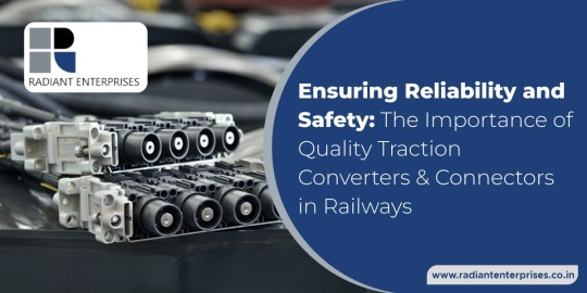
Ensuring Reliability and Safety: The Importance of Quality Traction Converters and Connectors in Railways
Introduction
The modern railway industry is evolving at a rapid pace, with advancements in technology playing a crucial role in enhancing efficiency, sustainability, and safety. Among the many components that contribute to the seamless functioning of a railway system, traction converters and connectors stand out as vital elements. This blog explores the significance of quality railway traction converter manufacturer and railway traction connector manufacturer in ensuring the reliability and safety of railway operations, with a specific focus on manufacturers in this domain.
Railway Traction Converters: The Powerhouses of Rail Mobility
Railway traction converters manufacturers play a pivotal role in the electrification of trains. These devices are responsible for converting electrical power from the grid into the appropriate form for the efficient and controlled movement of trains. As the demand for electrified rail systems grows, the role of railway traction converters manufacturers becomes increasingly critical.
Advancements in Traction Converter Technology
Leading manufacturers in the field of railway traction converters are at the forefront of innovation. They constantly strive to develop converters that are not only more efficient but also environmentally friendly. The integration of cutting-edge technologies, such as regenerative braking systems and advanced power electronics, contributes to the reduction of energy consumption and environmental impact.
Reliability Challenges and Solutions
Ensuring the reliability of traction converters is paramount for the uninterrupted operation of rail services. Manufacturers invest significantly in research and development to address challenges related to overheating, voltage fluctuations, and system failures. Robust testing procedures and quality assurance measures are implemented to guarantee the reliability of these critical components.
Railway Traction Connectors: Linking Efficiency and Safety
Railway traction connectors play a crucial role in ensuring the seamless transmission of power between various components of the rail system. These connectors serve as the interface between the traction converter and the train, facilitating the efficient transfer of electrical energy for propulsion.
Key Considerations in Connector Design
Manufacturers specializing in railway traction connectors prioritize several key considerations in their design and production processes. These include factors such as durability, weather resistance, and ease of maintenance. The harsh operating conditions that railways often face, including exposure to extreme weather and mechanical stress, necessitate connectors that can withstand such challenges without compromising performance.
Innovations in Connector Technology
In response to the evolving needs of the railway industry, manufacturers are continually innovating their connector designs. The integration of smart technologies, such as sensor-equipped connectors capable of real-time monitoring, enhances the safety and reliability of railway operations. These innovations contribute to the prevention of malfunctions and enable proactive maintenance measures.
Post Insulator for Railways: Ensuring Electrical Isolation and Safety
Post insulators for railways are critical components in railway electrification systems, providing electrical insulation and preventing current leakage. They play a crucial role in ensuring the safety of both passengers and railway personnel.
Importance of Quality Insulators
Railway electrification systems are subject to high voltage, and the quality of post insulators is paramount in maintaining electrical isolation. High-quality insulators prevent flashovers and electrical breakdowns, reducing the risk of accidents and disruptions. Manufacturers specializing in post insulators for railways adhere to stringent quality standards to meet the safety requirements of modern rail systems.
Challenges in Insulator Performance
The performance of post insulators can be affected by various factors, including environmental conditions, pollution, and mechanical stress. Manufacturers address these challenges through the use of advanced materials and coatings that enhance insulator resistance to environmental factors. Ongoing research and development efforts focus on improving the longevity and reliability of post insulators.
Choosing the Right Manufacturers: A Key to Reliability and Safety
Selecting reliable and experienced manufacturers is crucial for railway operators looking to ensure the longevity and safety of their electrified rail systems. Whether it is traction converters, connectors, or post insulators, the expertise and commitment of manufacturers significantly impact the performance of these components.
Key Criteria for Manufacturer Selection
Railway operators should consider several key criteria when choosing traction converter, connector, and post insulator manufacturers. These include a proven track record, adherence to industry standards, the use of advanced technologies, and a commitment to continuous improvement. Collaborating with reputable manufacturers enhances the likelihood of deploying systems that meet or exceed safety and reliability expectations.
Conclusion
In conclusion, the reliability and safety of railway systems depend heavily on the quality of traction converters, connectors, and post insulators. Manufacturers in these domains play a critical role in advancing technology to meet the evolving needs of the railway industry. As electrification becomes more prevalent, ensuring the highest standards in the design, production, and maintenance of these components is essential for the seamless, efficient, and safe operation of rail networks worldwide.
#Post Insulator For Railways#Railway Traction Converter Manufacturers#India#Railway Traction Connectors Manufacturers#railway#third rail#locomotive#tram#metro#railway engine
7 notes
·
View notes
Text
Nante's Rugged Surge Defense Cabinets Protect Critical Equipment
In demanding industrial environments, an industrial socket box serves as the first line of defense against harmful electrical surges. When power fluctuations occur, sensitive machinery and control systems face the risk of damage or unexpected downtime. Equipped with built -in surge arresters and reinforced wiring paths, this enclosure transforms an ordinary outlet cluster into a resilient safeguard. By channeling sudden voltage spikes safely to ground, it preserves the integrity of downstream devices and maintains continuous operation under challenging conditions.
Surge events often result from lightning strikes, utility switching, or internal motor start -ups. Without proper dismissal of these transient spikes, equipment may suffer insulation breakdown, circuit board failures, or degraded operational life. The specialized arresters within these distribution cabinets feature metal oxide varistors or gas discharge tubes that respond within nanoseconds, shunting excess energy away from critical circuits. Unlike generic power strips, these systems integrate protective modules directly at distribution points, minimizing cable lengths and reducing vulnerability.
Design considerations extend far beyond simple surge modules. Industrial enclosures demand robust construction materials that withstand dust, moisture, and mechanical impact. Rugged polycarbonate or powder -coated steel housings with high ingress ratings seal out contaminants while allowing heat dissipation through dedicated vents. Reinforced knockouts and strain relief clamps secure conduit entries, preventing accidental cable displacement. Together, these features form a comprehensive barrier against harsh elements and electrical threats alike.
Maintenance accessibility remains a key advantage. Hinged service doors with secure latches grant technicians swift entry without full disassembly. Internal busbars and terminal strips arrange wiring in orderly rows, each protected by individual circuit breakers or fuses. Visual indicators, such as LED status lights, display arrester health, signaling replacement needs before protective capacity diminishes. Field -replaceable cartridges simplify upkeep, ensuring that surge defense remains optimal without extensive downtime or specialized tools.
Modern control centers also benefit from integration with monitoring networks. Select enclosures embed voltage sensing modules that relay power quality metrics over industrial buses or wireless links. Facility managers access real -time dashboards showing transient count, surge magnitude, and device status. Predictive alerts flag abnormal surge activity, prompting preventive measures before equipment degradation occurs. This connectivity elevates protective hardware into an intelligent component of a larger asset management ecosystem.
Safety certifications underpin confidence in these solutions. Compliance with stringent standards for surge protection, electrical insulation, and fire resistance guarantees that installed units meet rigorous performance benchmarks. Inspections by accredited bodies ensure that manufacturing processes uphold consistent quality. By choosing certified enclosures, operators demonstrate due diligence and often satisfy insurance requirements for damage prevention measures in high -value installations.
Customization options allow precise matching to application demands. Modules support varied protection levels, from lower clamping voltages ideal for sensitive control circuits to heavy -duty arresters suited for main distribution feeders. Additional features include integrated isolation switches, remote trip capabilities, and selectable grounding configurations. Whether deployed in outdoor substations, mobile power carts, or plant automation racks, these configurable cabinets adapt to site -specific requirements with ease.
Environmental considerations also influence material selection and lifecycle impact. Many suppliers prioritize recyclable housing materials and RoHS -compliant components that exclude hazardous substances. Energy -efficient designs minimize standby losses, and recycled feedstock reduces overall carbon footprint. Take -back programs for spent arrester cartridges promote circular reuse, aligning protective infrastructure with broader sustainability goals favored by forward -thinking organizations.
Investing in a robust surge defense cabinet yields tangible returns. Protected equipment experiences fewer unplanned stoppages, reducing repair costs and lost productivity. Extended component lifespan delays replacement cycles and contributes to predictable maintenance budgeting. Enhanced uptime translates into smoother operations, whether supporting continuous manufacturing lines, critical research facilities, or remote telecommunications towers that demand uninterrupted power quality.
By integrating advanced surge mitigation techniques, rugged construction, and smart monitoring capabilities, a modern industrial socket box delivers comprehensive defense for valuable systems. Choose this high -performance solution to safeguard motors, drives, sensors, and control panels against unpredictable electrical disturbances. For more information about scalable enclosures and tailored protective options, visit https://www.nante.com/product/ .
0 notes
Text
How to choose silicon TVS Diode devices
These transient phenomena arise from the sudden release of stored energy, generated by various internal and external sources. Common causes of transients include normal switching operations of power supplies and electromechanical equipment, fluctuations in AC lines, lightning surges, and electrostatic discharge (ESD).
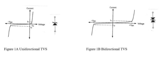
Silicon avalanche diodes feature large connection points to enable high surge current handling capability. Their key characteristics include extremely fast response time and low dynamic impedance in avalanche mode. TVS diodes offer several advantages, including:
Low clamping voltage
No wear limit
Compact physical size
Wide voltage range
High transient power dissipation
These devices are available in various axial lead and surface-mount plastic packaging. For applications requiring extremely high transient absorption capacity, MDE Semiconductor provides customized and standard TVS solutions, including a complete series of high-current stacked components.
However, regardless of the application, selecting specific device parameters involves understanding key TVS benchmarks and criteria.
TVS Key Terms
Before discussing how to choose a TVS, certain key terms must be defined:
l Minimum Breakdown Voltage (VBR): The voltage at which the TVS becomes transient (the device enters avalanche breakdown), creating a low-impedance path.
l Test Current (IT): The current at which the breakdown voltage is measured.
l Rated Working Voltage (VRWM): The maximum rated DC operating voltage, at which the TVS remains in a non-conductive mode (also known as the working voltage).
l Maximum Reverse Leakage Current (IR): The highest current measured during normal operation.
l Maximum Peak Pulse Current (IPP): The maximum allowable surge current the device can withstand.
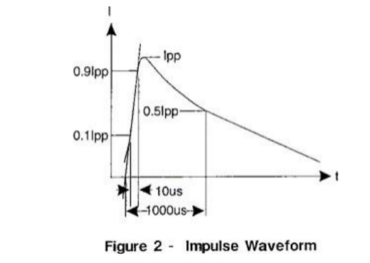
Rated Power and Surge Waveform
One of the most widely recognized surge wave forms is the double exponential pulse (Figure 2), defined by its rise time (tr) and duration (tp). The pulse duration (tp) is the time for the pulse current to decay to 50% of IPP. For example, a 10 × 1000 μs pulse has a 10 μs rise time and decays to 50% of its peak value within 1 ms.
The rated power of a suppressor is the product of VC and IPP:
Pp = VC × IPP
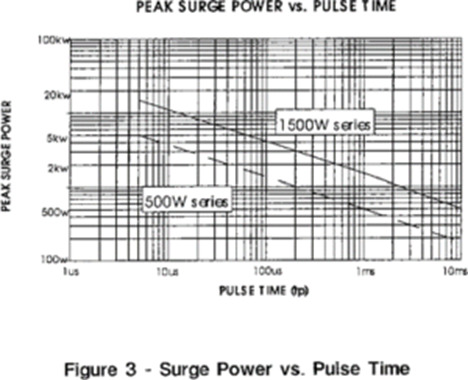
Guidelines for Choosing the Correct Transient Voltage Suppressor
Leiditech recommends the following steps to select devices for optimal transient suppression:
1. Determine the circuit’s maximum DC voltage or continuous operating voltage, considering nominal voltage and “high-side” conditions.
2. Select a TVS with a reverse isolation voltage (VRWM) equal to or greater than the circuit’s operating voltage.
3. Ensure the TVS draws negligible current under normal operation. A too-low working voltage may cause avalanche breakdown or excessive leakage current, affecting circuit performance.
4. Evaluate Peak Pulse Power (Pp): Characterize the circuit’s transient conditions (waveform, source, and pulse duration). Choose a TVS that can dissipate the expected peak pulse power.
5. Specify Maximum Clamping Voltage (VC): Select a TVS with a clamping voltage lower than the threshold that could damage the circuit.
Unidirectional vs. Bidirectional TVS
A common misconception is that bidirectional TVS diodes are needed to suppress negative transient pulses. In reality, bidirectional TVS diodes are essential for:
l Communication applications or data lines with positive/negative signal oscillations.
l Applications requiring reduced capacitance.
For circuits with only positive signal levels, a unidirectional TVS is typically sufficient.
Operation principle:
l Under positive transients, the device avalanches and conducts in the reverse breakdown direction.
l Under negative surges, it conducts like a forward-biased diode, absorbing transient energy (except for low-capacitance devices, which must be bidirectionally connected to protect internal diodes from reverse surges).
Temperature Considerations
Transient voltage suppressors are designed for operation over a wide temperature range (typically -55°C to +155°C). For applications with specific temperature requirements, consider:
l Reverse Current (IR): Increases with temperature; refer to the datasheet for high-temperature leakage limits.
l Power Dissipation: Decreases as junction temperature rises. Peak power derates linearly from +25°C to the maximum rated temperature (Tmax); see the power derating curve for examples.
l Breakdown Voltage Temperature Coefficient (TCBV): Specified in the datasheet as the percentage change in VBR per degree Celsius.
If you’d like to learn more or have any questions, don’t hesitate to reach out:
Visit us at [en.leiditech.com]
#TVSDiodes #CircuitProtection #ESDProtection #SurgeProtection #Leiditech #ElectronicsDesign #PowerElectronics #TransientVoltage #TechTips #EngineeringSolutions #ElectronicComponents #DesignSmart #TVSGuide #EMCDesign
0 notes
Text

How to Disconnect and Connect a Vehicle Battery: Correct Order and Technical Reasons
When working with a car battery, following the correct order for disconnecting and connecting cables is not only a practical recommendation, but a fundamental technical safety measure. Here we explain the procedure and the technical reasons behind each step.
Disconnection (to avoid short circuits):
Negative first, disconnect.
The negative cable is the one connected to the vehicle's ground. Removing it first breaks the entire electrical circuit. This means that even if you accidentally touch the positive terminal and a metal part of the vehicle with a tool, a short circuit will not occur because the circuit is no longer closed.
Positive then, disconnect.
Once the negative terminal is isolated, the positive terminal can be safely removed. If this order is reversed and the positive terminal is disconnected first, any accidental contact with metal parts could cause an electric arc or a severe short circuit, as the chassis is still connected to the negative terminal.
Connection (to ensure controlled power flow):
Positive first, connect.
When installing a new battery or reconnecting an existing one, the positive cable must be connected first. This allows the system to receive voltage without having a completely closed circuit, reducing the risk of sparks or electric shock if accidental contact with the chassis occurs.
Negative cable is then connected.
Finally, the negative cable is connected, completing the electrical circuit. Since the system is already properly connected to the positive terminal, any electronic components receive stable and safe power.
The vehicle's metal chassis acts as a current return (ground), so any accidental contact between the positive terminal and the vehicle body can unintentionally close the circuit if the negative cable remains connected. Disconnecting the negative cable first eliminates this possibility. When reconnecting, connecting the positive cable first ensures that no current flows to the ground until everything is properly secured.
0 notes