#CFDConsultingServices
Explore tagged Tumblr posts
Text
Design and Validation of TEMA S Class Heat Exchanger
Designing and validating TEMA S-Class heat exchangers. Get expert tips and insights!
You can come up with new routes by teaming up with a leading Stress Analysis Services Partner or Product Design Companies with a good reputation.
0 notes
Text
Leading CFD Analysis and Consulting Services in India
TEFUGEN, a leading consulting service provider in Computational Fluid Dynamics (CFD), has secured a distinguished position among India's top CFD companies. With a focus on precision in simulations and delivering valuable insights, we have earned the trust of businesses seeking CFD expertise. This highlights the company's capabilities, emphasising its unwavering commitment to excellence and substantial contributions to the CFD landscape in India.
Mastery in CFD Simulation:
Our dedicated team of highly skilled engineers excel in conducting various CFD simulations, analysing complex flow patterns, optimising designs, and addressing any problem in Fluid Dynamics.
Demonstrated Success Stories:
Through impactful case studies and client projects, we manifest how our advanced simulations and tailor-made solutions directly contribute to improved designs, heightened performance, and cost-effective solutions across diverse industries.
Tailored Solutions Across Varied Industries:
TEFUGEN caters to a broad spectrum of industries, tailoring CFD solutions to unique requirements, from Aerodynamic analysis to Thermal simulations and beyond.
Sophisticated Tools and Techniques:
Equipped with state-of-the-art CFD software such as ANSYS and OpenFOAM, we ensure the highest accuracy and efficiency in simulations. We stay abreast of the latest advancements in technology to address complex challenges with precision, providing detailed technical reports.
Integration Method and Client Satisfaction:
Emphasising collaboration and client satisfaction, TEFUGEN actively involves clients in the simulation process, ensuring alignment with expectations and providing actionable insights. Our goal is to exceed expectations at every project stage.
By prioritising collaboration and client satisfaction, Tefugen ensures clients achieve optimal designs, improved performance, and cost-effective solutions. For more information, contact us at [email protected].
#cfd#computationalfluiddynamics#cfdduct#ductoptimization#cfdconsultingservices#cfdanalysisserviceprovider#bestcfdservice#tefugen#bestengineeringserviceprovider#tefugentechnologies#cfdoptimization#ductflowoptimization#oilandgas#powerplant#refineries#automobile#airtransport#transportation#processindustries#chemicalindustries#buildingsandstructures#cfdservicesinindia#cfdaerospace#cfdpowersector#cfdautomobile#cfdoilandgas#cfdhvac#cfdturbomachinery#cfdelectronics
0 notes
Text


#cfd#fea#cad#performancetesting#fes#manufacturing#tefugen#engineeringserviceprovider#engineeringsolutionprovider#cfdconsultingservice#cfdanalysisservice#feaconsultingservice#cfddraftingservice#boiler#cleanairflowtest#dirtyairflowtest#gasdistribution#coldairvelocitytest#airpreheater#performance#airandgasanalysis#testing#boilertesting#boileroptimization#powerproductionoptimizaion#boilercapacityoptimization#fluegastesting#fluegasflowoptimization#ductoptimization#boilerducttesting
0 notes
Text
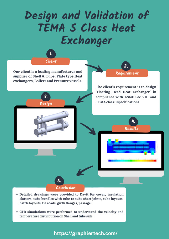
Design and Validation of TEMA S Class Heat Exchanger
Our client is a leading manufacturer and supplier of Shell & Tube, Plate type Heat exchangers, Boilers and Pressure vessels. The client’s requirement is to design ’Floating Head Heat Exchanger’ in compliance with ASME Sec VIII and TEMA class S specifications.

What we Delivered:
3D CAD Model as per Client’s requirement/specifications
General Arrangement Drawings
Fabrication drawings
Machine drawings of various components
Parts drawings of various components
Detailed Bill of materials
CFD simulations to ensure customer’s design criteria is met
FE simulations to ensure structural integrity during lifting, transportation.

Design Specifications:
The Floating Head Heat Exchanger is designed for:
Pressure rating: Shell side: 38 kg/sq. cm, and Tube side: 30 kg/sq. cm
Temperature rating: Shell side: 150 °C and Tube side: 110 °C
Fluid capacity, Shell side: 2.8 cu.m., and Tube side: 1.8 cu.m
No. of passes: shell side (cross flow) and tube side (10).
Design wind reluctance: 50 m/s as per IS 875 Part 3
Seismic design code: IS: 1893-2005
Insulation thickness is 15/50 mm.
Gross weight of Heat exchanger (empty): 13 tons
Through simulations, we were able to provide nozzle loads, wind seismic data, bolt torque and forces, and welding stresses and forces.
Detailed drawings were provided to Davit for cover, insulation clatters, tube bundles with tube-to-tube sheet joints, tube layouts, baffle layouts, tie roads, girth flanges, passage partitions, gaskets, hold points, name plates, etc.
Finally, all design information, like native 3D CAD data, drawings and simulation reports, was submitted to the customer.

CFD Analysis validation:
CFD simulations were performed to understand the velocity and temperature distribution on Shell and tube side. The heat exchanger was simulated with operating temperature and pressure. The intensity of turbulence, heat transfer rate was studied and the results are reported to ensure that the design is in compliance with requirement and efficiency of the system is achieved.
The best way to obtain the accurate information is to consult an experienced CFD Consulting Services or Structural Analysis Services provider.
0 notes
Text
Design and Validation of TEMA S Class Heat Exchanger
Step-by-step methods for designing and validating TEMA S-Class heat exchangers. Get expert tips and insights!
0 notes
Text
High Velocity Oxygen Fuel Nozzle Spray CFD ANALYSIS

Uncover the secrets of HVOF nozzle spray with CFD analysis. Explore internal flow, particle behavior, and optimize coating formation for superior results.
The best way for you to get the necessary information is by contacting a reputable CFD Consulting Services or a Structural Analysis Services provider.
#CFDAnalysis#CFDConsultingServices#DiscretePhaseModelling#flowrate#graphlertech#HighVelocityOxy-Fuel#HVOF
0 notes
Text
High Velocity Oxygen Fuel Nozzle Spray CFD ANALYSIS

INTRODUCTION
High Velocity Oxy-Fuel(HVOF) Spray is used to coat corrodible components with resistive materials. It utilizes highly compressed fuel that combust with oxygen to accelerate the momentum and temperature of the particle and also to make the flow supersonic.
Supersonic nature of flow in an atmospheric condition producing sequential pressure expansion and contraction letting out a phenomenon called Shock Diamonds. These Shock Diamonds a.k.a pressure pulsations produced due to hyper pressure gradient with respect to atmospheric pressure.
With the aid of the CFD technology, the complex Pressure Gradient of supersonic flow nature can be vividly captured and the design progress can be accelerated. Thus, CFD is an important tool for Flow physics as it will reduce the time consuming and expensive experimental procedures.
SCOPE OF THIS RESEARCH WORK
To model the combustion of fuel and oxygen in a compressed chamber.
Get a higher temperature and velocity pulsation proportional to pressure pulsation.
Injection of spray material using Discrete Phase Modelling (DPM).
MODEL ACQUISITION PROCESS
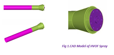
The HVOF Setup is experimentally analysed in Annamalai University, Chidambaram. From the resource the component is manually measured and the model is generated in CAD software package Pro-E Wildfire 5.0.
CFD ANALYSIS
With a goal of capturing shock diamonds of the supersonic flow of HVOF Spray, CFD is utilized in a following systematic way.
The best way for you to get the necessary information is by contacting a reputable CFD Consulting Services or a Structural Analysis Services provider.
VALIDATION STUDY
CFD procedure has lot of variables such as grid count, turbulence model, and discretization scheme, so it is important for a CFD engineer to play between those variables without affecting the solution accuracy. A commercial Computational Fluid Dynamics (CFD) code, ANSYS CFX V14.5 with a k-ε Standard turbulence model with Eddy Dissipation Model for combustion was used and the impact of supersonic flow in an atmospheric pressure and the Pressure pulsation was obtained.
The numerical results are compared with the experimental data to arrive at the best computational procedure (BCP) and Discrete Phase Modelling (DPM) is proceeded to introduce the surface coat material into the domain.
INFLUENCE OF CFD TECHNIQUE IN THIS PROBLEM
The Shock Diamond occurrence mainly depends on the hyper pressure difference between the atmosphere and combustion chamber. It depends on the flow rate of fuel, oxygen and volume of the combustion chamber.
Working with a leading Stress Analysis Services provider or well-known Product Design Companies will make new routes possible.

CONCLUSION
A Special phenomenon of Fluid flow is acquired in computational methodology
Surface Coat material injection and Combustion of fuel-oxygen is modelled
#CFDAnalysis#CFDConsultingServices#DiscretePhaseModelling#flowrate#graphlertech#HighVelocityOxy-Fuel#HVOF
0 notes
Text
IMPORTANCE OF CFD IN IMPROVING THERMAL BEHAVIOR OF SHELL AND TUBE HEAT EXCHANGER (STHE)
Discover how CFD boosts heat exchanger performance. Dive into fluid dynamics for optimal results.
CFD technologies and Structural Analysis Services are getting to be more of a necessity in the achieving of the objectives.
Reach out Graphler technology for a Stress Analysis Services .We are also specialized in Structural Design Services and more.
#Baffles#CFD#CFDConsultingServices#ComputationalFluidDynamics#graphler#HEATEXCHANGER#HOWTOIMPROVE#SHELLANDTUBEHEATEXCHANGER#turbulenceeddydissipation
0 notes
Text
IMPORTANCE OF CFD IN IMPROVING THERMAL BEHAVIOR OF SHELL AND TUBE HEAT EXCHANGER (STHE)

INTRODUCTION
Heat exchangers are important engineering systems with a wide variety of applications including power plants, nuclear reactors, refrigeration and air-conditioning systems, heat recovery systems, chemical processing and food industries.
Due to the high consumption and reduced availability of fuel resource, high thermal performance heat exchanger have been subject to great interest over decades.
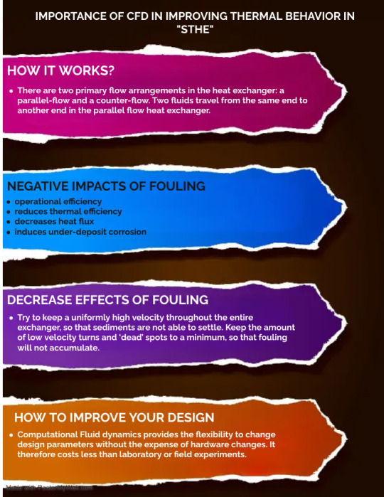
Typically, two fluids with different temperatures circulate through the heat exchanger in natural or forced convection manners and the thermal energy is exchanged via surfaces during the process. There are two primary flow arrangements in the heat exchanger: a parallel-flow and a counter-flow. Two fluids travel from the same end to another end in the parallel flow heat exchanger. For the counter-flow arrangement, the two fluids run in the opposite direction from two ends of the heat exchanger.
When using heat exchangers it is always the possibility that the fouling will occur. Fouling is generally defined as the deposition and accumulation of unwanted materials such as scale, algae, suspended solids and insoluble salts on the internal or external surfaces of processing equipment including boilers and heat exchangers.
operational efficiency
reduces thermal efficiency
decreases heat flux
induces under-deposit corrosion
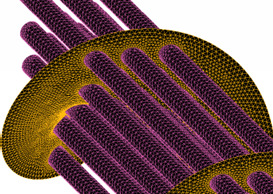
On most industries today, a major economic drain may be caused by fouling. The total fouling related costs for major industrialised nations is estimated to exceed US$4.4 million annually. One estimate puts the losses due to fouling of heat exchangers in industrialised nations to be about 0.25% to 30% of their GDP.
DESIGN CONSIDERATIONS TO DECREASE EFFECTS OF FOULING
There are a number of accommodations a designer may use once they have figured out how much fouling to expect in a particular unit.
Try to keep a uniformly high velocity throughout the entire exchanger, so that sediments are not able to settle. Keep the amount of low velocity turns and ‘dead’ spots to a minimum, so that fouling will not accumulate. CFD Consulting Services cover a wide range of experience and advice that are for the heat exchange systems improvement.
HOW TO IMPROVE YOUR DESIGN WITHOUT DOING EXPERIMENTS?


With the increasing trend in which industrial organizations are geared towards sustainability and cost-effectiveness, CFD technologies and Structural Analysis Services are getting to be more of a necessity in the achieving of the objectives.
Power of CFD
Provides better insight and foresight to the problem
Reduces the total product cycle time
Cuts the expensive experimental procedures

FINDINGS
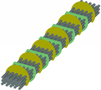
Baffles were introduced to develop turbulence inside the shell. It is absorbed that the helical baffle provides better cascading effect thus results in increased, uniform eddy dissipation inside the domain (Figure 6 – 15000m2/s3).
Reach out Graphler technology for a Stress Analysis Services .We are also specialized in Structural Design Services and more.
#Baffles#CFD#CFDConsultingServices#ComputationalFluidDynamics#graphler#HEATEXCHANGER#HOWTOIMPROVE#SHELLANDTUBEHEATEXCHANGER#turbulenceeddydissipation
0 notes
Text
IMPORTANCE OF CFD IN IMPROVING THERMAL BEHAVIOR OF SHELL AND TUBE HEAT EXCHANGER (STHE)
Discover how CFD boosts heat exchanger performance. Dive into fluid dynamics for optimal results.
#Baffles#CFD#CFDConsultingServices#ComputationalFluidDynamics#graphler#HEATEXCHANGER#HOWTOIMPROVE#SHELLANDTUBEHEATEXCHANGER#turbulenceeddydissipation
0 notes
Text
Enhancing Energy efficiency in ATM cabin and DATA centers using CFD Analysis
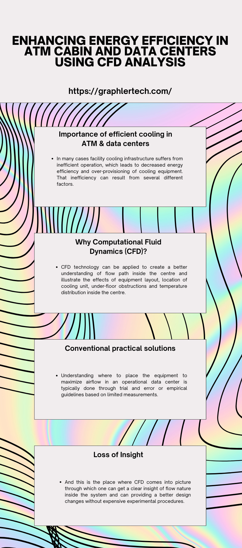
Discover how CFD analysis optimizes energy use in ATM cabins & DATA centers. Enhance efficiency &reduce costs. Learn more!
Contact a well-known CFD Consulting Services or a Structural Analysis Services provider to acquire the required information.
#airflowdistribution#airconditioningunits#ATM&datacenters#CFDAnalysis#CFDConsultingServices#Energyefficiency#finiteelementanalysis#StressAnalysisServices
0 notes
Text
Enhancing Energy efficiency in ATM cabin and DATA centers using CFD Analysis
Introduction
Banks and other entities are continued to be challenged by the increase in demand for energy utilization of commercial made air-conditioning units for cooling of ATM centers & data centers. In operational perspective, this means more energy is utilized and thus more the running over-head cost per year.
In this case, the existing cooling infrastructure may not be suitable or efficient which make those involved in ATM and data center must integrate design and operational priorities to ensure long term viability of their facilities.
Importance of efficient cooling in ATM & data centers
However, in many cases facility cooling infrastructure suffers from inefficient operation, which leads to decreased energy efficiency and over-provisioning of cooling equipment. That inefficiency can result from several different factors. For example, the cooling airflow is not distributed according to the demands of the equipment, or the discharged hot air is not properly contained or vented.
With continuing increases of heat generation in ATM & data centres, plus dramatically rising energy costs, banks and other entities are coming under greater pressure to improve the efficiency of cooling systems and reduce power consumption.
Why Computational Fluid Dynamics (CFD)?
CFD modelling would enable data centre mangers to accurately depict and understand the use of cooling resources and allow for appropriate infrastructure right-sizing. This could significantly help prevent organizations from under- or over-provisioning the infrastructure. Instead of buying cooling equipment they do not need, they might discover that they can simply reposition what they have.
Contact a well-known CFD Consulting Services or a Structural Analysis Services provider to acquire the required information.
Conventional practical solutions
It’s currently estimated that, on average, 5-10 percent of company’s budgets are dedicated to energy costs. This percentage will rise, inevitably. It seems that government mandates will soon force facilities operators to reduce energy consumption. Many companies are already evaluating and/or implementing alternative solutions to reduce their energy use and make data centre cooling processes more efficient.
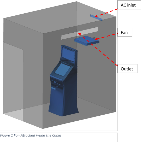
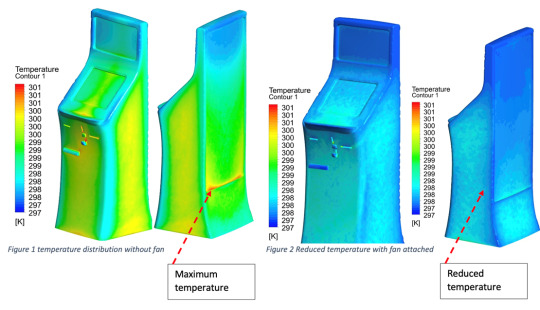
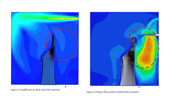
Flow pattern inside a general ATM cabin is studied using CFD technique. In this study, air flow from AC duct is applied into the cabin to study the flow nature and the operating temperature range over the ATM machine.
In order to have a good air circulation a fan is introduced under the AC duct as shown in figure 2. And the suction through the fan is found to have a good flow pattern and reduced temperature distribution over the machine as shown in figure 6.
Loss of Insight
These methods often do not consider the complex fluid dynamics that govern air flow distribution, and consequently do not produce the expected flow rates. An adjustment in one section of the data center will affect flow rates throughout the other areas. This kind of design procedure is labor-intensive, time-consuming and expensive –and still seldom yields an optimal, efficient solution.
And this is the place where CFD comes into picture through which one can get a clear insight of flow nature inside the system and can providing a better design changes without expensive experimental procedures.
Collaborating with the best Stress Analysis Services provider or top Product Design Companies will open up new ways.
#airflowdistribution#airconditioningunits#ATM&datacenters#CFDAnalysis#CFDConsultingServices#Energyefficiency#finiteelementanalysis#StressAnalysisServices
0 notes
Text
Enhancing Energy efficiency in ATM cabin and DATA centers using CFD Analysis
Discover how CFD analysis optimizes energy use in ATM cabins & DATA centers. Enhance efficiency & reduce costs. Learn more!
#airflowdistribution#airconditioningunits#ATM&datacenters#]#CFDAnalysis#CFDConsultingServices#Energyefficiency#finiteelementanalysis#StressAnalysisServices
0 notes
Text
Acoustic CFD Analysis in Valves

Explore how Acoustic CFD Analysis improves valve performance. Unlock efficiency and optimize your systems with this groundbreaking approach.
#AcousticCFDAnalysis#AcousticModelling#CFDAnalysis#CFDConsultingServices#controlvalve#Noisetrim#StructuralDesignServices
0 notes
Text
Acoustic CFD Analysis in Valves
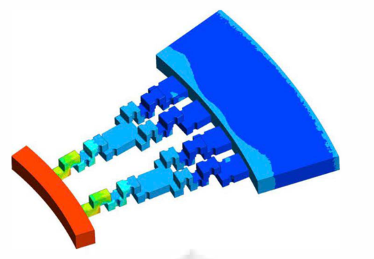
Why is Acoustic Modelling important?
Acoustic waves are pressure pulses travelling through a compression medium at the speed of sound in that medium. Predicting valve acoustics is very tedious and costly for running experiments in laboratory inorder to evaluate the effectiveness of one design over the other.
Predicting valve acoustics using CFD has become possible with advanced computational capabilities and different turbulent models such as RANS & LES to evaluate the pressure sound levels with reasonable accuracy. Using CFD stands to the reason that if we could understand the turbulent time varying nature of pressure fields, we could calculate the noise generated in the valve trim with reasonable accuracy and that with just a fraction of cost and time in comparison to a physical laboratory experimention and measurements.
Role of Noise trim and CFD analysis to predict Acoustic level:
In a control valve where pressurized gas, steam or vapor is flowing contains enormous amount of potential energy. This stored potential energy is converted into other forms such as turbulent fluid motion, heat, sound waves, vibration etc.
Majority of sound generated in a control valve is due to turbulent fluid motion. Turbulence causes large pressure fluctuations due to the formation of eddies of all sizes. The size of the eddy and fluid velocity determines the frequency of pressure fluctuation. Larger eddies produce lower frequency noise and vice versa.Obtain reliable insights from an excellent CFD consulting services or an Structural Design Services company.
For this reason Noise trims are used to reduce the aerodynamically generated noise by the fast moving fluid stream. This is done by increasing the pressure drop of the fluid in the trim. This is done in Single and multi-stage noise trim by staging the pressure drop and bypassing the flow through many openings.
CFD analysis provides substantial insight on the pressure fluctuation, intensity of turbulence, pressure drop across stages and Acoustic level in the noise trim. This helps product development team to virtually validate the noise attenuation ability of that particular design.
The following observations can be made -
Pressure contour (left) and velocity vectors (right) shows supersonic flow through the low noise trim.
Calculate acoustical conversion efficiency at each stage of the noise trim.
Intensity of turbulence coming into each stage due to restrictions.
Evaluate pressure drop ratio at each stage.
Coimbatore has the best Stress analysis services, which are provided by Graphler Technology Solution. A team which is well experienced with 10 years industrial knowledge. Visit our websites or contact us for more information.
#AcousticCFDAnalysis#AcousticModelling#CFDAnalysis#CFDConsultingServices#controlvalve#Noisetrim#StructuralDesignServices
1 note
·
View note
Text
Explore how Acoustic CFD Analysis improves valve performance. Unlock efficiency and optimize your systems with this groundbreaking approach.
#AcousticCFDAnalysis#AcousticModelling#CFDAnalysis#CFDConsultingServices#controlvalve#Noisetrim#StructuralDesignServices
0 notes