#Airspeed Group of Companies
Explore tagged Tumblr posts
Visit Tumblr Blog
Explore Tumblr blogs with no restrictions, modern design and the best experience.
Last Seen Tumblr Blogs


Fun Fact
Mobile Tumblr US users spend an average of 4.04 minutes per session on the app.
Text
Born To Die - Chapter 4
Chapter Summary: The training course starts and a big fight breaks out among the detachment
A/N: I hope y'all enjoy the chapter. Any and all feedback is appreciated.
Everyone was just getting in for the day when Allison’s attention was drawn to Jake and Javy. They were looking at one of the pictures in the room and curiosity got the best of her. Erin wasn’t there yet to keep her company and as mad as she was a t Jake, Javy was still her friend.
“What are you boys looking at?” Allison approached them and leaned down to look at the picture.
“It’s Maverick’s Top Gun class,” Javy pointed out. Jake stayed uncharacteristically quiet, “But look who’s standing next to him.”
Allison’s eyes were drawn to a man who looked very familiar. Upon closer inspection she realized it was Bradley’s dad. Erin had told her the very surface details of what happened with the mission that took Bradley’s dad away one night. Allison sent a worried look over to Javy and Jake, hoping that maybe they would let this one go and not bring it up.
“Let’s leave the dead to rest, please,” Allison asked softly before walking away from the boys. She didn’t even look back, but if she did she would’ve seen Jake’s eyes following her across the room. She looked to the entrance of the room to see Bradley and Erin walking in and conversing as if nothing was wrong. Allison would be lying if she said she wasn’t surprised by it.
“Allie!” Erin smiled, “You left early this morning, I didn’t even hear you get up.”
“Yeah, I just needed to get a run in before work,” Allison responded.
“Good morning, Medusa,” Bradley greeted, not even a bit uneasy around either Erin or Allison for once.
“Rooster,” Allison nodded her head to him. She would accept a… temporary truce, for now. She still didn’t trust him, especially not around Erin, but if the two were on speaking terms then Allison wouldn’t interfere with that.
—
“Time is your greatest enemy,” Pete explained to the group of pilots, all sitting in a classroom-like setting. Allison and Erin sat right behind Javy and Jake and just to the right of Bradley, “Phase one of the mission will be a low-level ingress attacking two plane teams. You’ll fly along this narrow canyon to your target. Radar guided surface-to-air missiles defend the area. These SAMs, they’re lethal, but they were designed to protect the skies above, not the canyon below.”
“That’s because the enemy knows no one is insane enough to try and fly below them,” Bradley spoke up. Erin glanced over to him before looking back at their mission brief. An uneasy feeling settled in her stomach as she realized there was a good chance someone wasn’t making it back from this mission.
“That’s exactly what I’m gonna train you to do,” Pete responded to Bradley, his face devoid of any of his usual humor or wit. Erin had rarely seen him so serious, not in her years of knowing him as a kind of surrogate uncle. The only time she could remember was when her actual uncle had gotten cancer and broke the news to everyone over dinner. Erin didn’t think she’d ever forget that night.
“On the day, your altitude will be 100 feet maximum,” Pete continued to explain, “You exceed this altitude, radar will spot you and you’re dead. Your airspeed will be 660 knots minimum. Time to target, two and a half minutes. That’s because fifth-generation fighters wait at an air base nearby.”
As Pete continued to brief the pilots, Erin glanced over to Allison. The two women made eye contact with worry showing in both of their eyes. This wasn’t just any mission, this was a suicide mission. Erin could see her earlier conclusion reaching Allison as well. Somebody wasn’t making it back home this time.
Pete set up what the exercise of the day would be. They would lighten the parameters to start, but the exercise wouldn’t be easy. As everyone filtered out of the classroom to get ready all Erin could feel was a sense of worry and dread. She knew that out of all the two-seaters in their group, her and Allison were one of the best. They had proven that time and time again, but she didn’t think even their best would be enough for this mission.
—
The first run was Javy with Natasha and Robert. Allison had sat on the edge of her seat the entire time, watching the icons on the screen and listening to the radio chatter. A visible wince crossed her face as she watched Javy suddenly slow down and Natasha be forced above the ceiling parameter for the exercise. The three looked defeated as they came into the classroom to debrief their run.
“Why are they dead?” Pete asked Javy.
“We broke the 300 foot ceiling and a SAM took us out,” Natasha answered instead. Allison glanced over to Javy as an even deeper look of defeat crossed his face.
“No, why are they dead?” Pete dismissed Natasha and looked directly at Javy.
“I slowed down and didn’t give her a warning, it was my fault,” Javy responded.
“Was there a reason you didn’t communicate with your team?” Pete pressed.
“I was focusing on-” Javy began to respond.
“One that their family will accept at the funeral?” Pete cut him off with a grave facial expression. Allison couldn’t help the protective instinct welling up in her. It was just an exercise and he was doing the best he could. As if sensing her thought process, Erin laid a gentle hand on her arm as if to calm her.
“None, sir,” Javy responded.
“Why didn’t you anticipate the turn?” Pete turned to Natasha, “You were briefed on the terrain. Don’t tell me, tell it to his family.”
Natasha looked just as defeated as Javy as she glanced over to Robert. Allison looked at Erin, wondering just what she would say to Erin’s family if she ever lost her and it was her fault. How would she explain that to a family that barely wanted Erin to fly in the first place?
—
The next to go were Jake with Reuben and Mickey. If how he flew with Erin and Allison the day before was anything to go by, Erin did not have a good feeling about this run. He wasn’t listening to Reuben and leaving him in the dust. She could hear Reuben get both increasingly frustrated with him and fearful at the same time.
“What happened?” Pete asked Jake once the three had returned from their run.
“I flew as fast as I could,” Jake responded, “Kind of like my ass depended on it.”
“And you put your team in danger, and your wingman’s dead,” Bradley called him out. Erin and Allison both looked to be agreeing with Bradley as they turned their eyes back to Jake.
“They couldn’t keep up,” was all that came from Jake.
“Maybe if you would’ve listened to your team, this wouldn’t be a problem,” Erin heard Allison mutter next to her. Erin thought she might be seeing something, but it almost looked like Jake tensed after hearing Allison. She must be delusional though cause nothing ever phased Jake.
—
Then it came to Bradley with Allison and Erin. For the most part the course itself was going well except for the fact they were behind schedule by a large margin. Or at least a large margin when it came to the standards of flying fighter jets.
“Rooster, we’re 20 seconds behind and only getting slower,” Allison called out as they flew the course.
“We’re fine, speed is good,” Bradley dismissed her worry. Allison did not like that response, especially as she watched the timer keep counting down.
“Increase to 500 knots,” Allison tried to direct him.
“Negative, Medusa, hold your speed,” Bradley refused.
“Rooster, we’re way behind schedule,” Allison again tried to reason with him. She knew Bradley was a careful flier, someone who didn’t want to do anything reckless or endanger anyone. Allison just wished he saw it was just as dangerous to go slow.
“We’re alive,” Bradley countered, “We can make up time in the straightaway.”
“We aren’t going to make it, Rooster,” Allison sounded even more frustrated. Erin felt helpless in the backseat, listening to both of them argue with each other.
“Just trust me,” Bradley responded, “Maintain your speed, we can make it.”
And then they didn’t make it, at least not in time. They all went back up to the classroom to debrief their own run. If Erin hadn’t been there, Allison might’ve picked a fight with Bradley about the run. Fortunately for him, Erin was there and Allison had already shown one emotional outburst in front of her. No need for another one.
“Why are you dead?” Pete asked Bradley directly, “You’re team leader up there. Why are you, why is your team dead?”
“Because he doesn’t know how to listen to his team,” Allison commented.
“Yet you’re the only ones who made it to the target,” Natasha defended Bradley.
“A minute late,” Pete countered, “He gave enemy aircraft time to shoot him down. He is dead.”
“We don’t know that,” Erin spoke up, also coming to Bradley’s defense. Pete looked almost shocked at her speaking up.
“He’s not flying fast enough, you don’t have a second to waste,” came Jake’s overconfident voice from the front of the class.
“We made it to the target,” Bradley finally spoke up, countering Jake.
“And superior enemy aircraft intercepted you on your way out,” Pete said.
“Then it’s a dogfight,” Bradley responded.
“Against fifth-generation fighters?” Pete questioned him.
“Yeah, we’d still have a chance,” Bradley argued.
“In an F-18,” Pete began to raise his voice. Erin felt like she was watching her high school years all over again. Seeing Bradley and Pete at each other’s throats. Allison couldn’t honestly believe the amount of insubordination coming from Bradley.
“It’s not the plane, sir, it’s the pilot,” Bradley said.
“Exactly!” Pete yelled, staring him dead on. There was a moment of tense silence as the two reached a stand off.
“There’s more than one way to fly this mission,” Bradley finally said.
“You really don’t get it,” Jake said as Allison braced herself for the impending fight, “On this mission, a man flies like Maverick here, or a man does not come back. No offense intended.”
“Yet somehow you always manage,” Robert said as Jake aimed his last comment at Natasha. Erin had a hard time stifling the chuckle at Robert actually putting Jake in his place, knowing it was neither the time nor the place for it.
“Look, I don’t mean to criticize. You’re conservative that’s all,” Jake continued and all Allison could think was ‘why isn’t Maverick stopping this?’.
“Lieutenant,” Pete spoke up, a weak attempt to put an end to Jake’s tirade.
“We’re going into combat, son, on a level no living pilot’s ever seen,” Jake just pressed on, ignoring their instructor.
“Hangman,” Allison warned, also seeing where this was going.
“Not even him,” Jake ignored her as well, “That’s no time to be thinking about the past.”
‘What’s that supposed to mean?” Bradley turned to Jake, anger written all over his face.
“Rooster…” “Bradley…” Both Pete and Erin spoke up at the same time.
“I can’t be the only one that knows that Maverick flew with his old man,” Jake leaned back in his seat and continued to speak.
“Jake, stop,” Allison all but begged him.
“That’s enough,” Pete harshly turned to Jake.
“Or that Maverick was flying when his old man-” Jake got cut off at Bradley leaped at him, ready to throw a punch. It all happened so fast. Javy went to protect Jake. Erin went to stand in front of Bradley, though she was facing him as if to calm him down. Allison went to hold Jake back from starting anymore shit. Pete lept in between the two pilots, trying to get everyone to knock it off.
“You son of a bitch,” Bradley yelled at Jake as Erin began pushing him back and Robert helped her hold him off.
“Hey man,” Javy continued to protect Jake while also holding him back with Allison.
“I’m cool, I’m cool,” Jake shook both of them off. Allison couldn’t believe the amount of bs she just heard from him.
“That’s enough,” Pete cut in, tone harsh and firm.
“He’s not cut out for this mission,” Jake said, staring directly at Bradley.
“Jake, shut up,” Allison glared at the much taller man.
“You know I’m right,” Jake said to Pete as he walked out, intentionally walking by Bradley who was still being held back by Erin, Robert, Natasha, and Reuben.
“You’re all dismissed,” Pete said, looking around at all the pilots. Allison ran after Jake before Javy could while Erin pulled Bradley out of the classroom from a different exit. The rest of the pilots went their separate ways.
Tag list: @djs8891
#my oc#ocappreciation#top gun maverick oc#fd: top gun maverick#top gun oc#fd: top gun#top gun fanfiction#top gun maverick fic#bradley bradshaw fic#jake seresin fic#oc: erin bell#oc: allison delaney#li: bradley rooster bradshaw#li: jake hangman seresin#bradley bradshaw x oc#jake seresin x oc#rooster x oc#hangman x oc
4 notes
·
View notes
Text
Rise of the Ticket Agent: Airspeed's Rosemarie Rafael

Life sometimes has a way of telling you to switch lanes, whether in everyday situations or a career-alternating path altogether. This is something that Ms. Rosemarie Rafael, chairperson of logistics company Airspeed, a part of SM Investments Corporation’s portfolio investments, has learned over her 40-plus years of experience. She fondly looks back on her early years as a passenger ticketing and reservations agent for an airline company. As dedicated as she was to that role, she also recalls facing many challenges along the way. For instance, there was that one time she went back to her desk in tears after being locked out from a meeting she was late to by ten minutes. Her phone call with a client for the company ran a bit longer than expected, and she found herself ‘not needed’ anymore in the meeting.

Ms. Rosemarie Rafael at Airspeed. Photo by SM Investments Corporation. It’s as if spontaneously, the future founder of logistics company Airspeed will soon have one foot at the door into an industry she will lead one day when a phone call from a freight company presented an opportunity—she took it. Years later, she rose through the ranks. Venturing beyond her comfort zone, Ms. Rafael felt right to set out on her own—but not without being at a crossroads once more. The Airspeed story was set when she consulted her then-boss about her idea, the fact of leaving the currently recognized number-one company by the International Air Transport Association (IATA) came to mind. “Why be a small fish in a big pond?” her boss remarked. The answer to this was clear to Ms. Rafael, who said, “because it has so much room for growth.” Within five years of her company’s founding, Airspeed eventually claimed the number one spot in the IATA ranking. Ms. Rafael attributes this success to the relationships she built with her clients during the early stages that helped Airspeed thrive in the industry.

MNG Cargo Airlines Airbus A300B4-203F. Photo by Aero Icarus. Flickr. From a meek startup with six employees and a single delivery van, the company now has over a thousand skilled personnel and a fleet of vehicles that can be swiftly mobilized at more than 300-strong. Among of Ms. Rafael’s notable achievements is paving the way for women. Not only is she leading a successful business, but she has also established a formidable company in an industry that is commonly associated with the male demographic. The proud mother of four has been defying the odds. She also notes the distinct group of people that sets Airspeed apart from other logistics providers. For one, key decisions in the company are being made by empowered women. This is evident in female leaders making up 70% of Airspeed’s top executives and 45% of their middle-tier managers. Ms. Rafael has empowered them to lead a company that highlights solutions-based decisions to drive further progress and innovation.

Sky Express Cargo plane. Photo by Eric Salard. Wikimedia. She discusses how the empowerment of women in the company allows their innate vision and nurturing qualities to permeate throughout the company transcending the work done in Airspeed as it crosses to a personal level of trust. “Airspeed is known for the kind of people we have. We are a company of integrity and this is not to be compromised even in the hardest times,” Ms. Rafael said. “We prioritize our people and stakeholders. We believe that if we have happy people working for us, then we will have happy and satisfied customers.” Ms. Rafael’s journey tells a story of vision, commitment, and persistence. Her first few jobs may not have been the best fit for her, but she was composed and did everything to the best of her abilities. When it was clear she wanted to change, she followed through with her dream, all the lessons in tow, and established her company Airspeed. Sources: THX News & SM Investments Corp. Read the full article
0 notes
Text
LRMC, Airspeed to pilot first smart locker system in public transport
LRT-1 private operator Light Rail Manila Corporation (LRMC) has officially inked a deal with the Airspeed Group of Companies to activate PopBox in the Philippines and enable the first smart locker system available in a public transport terminal. Present during the partnership signing were (L-R) LRMC Head of Business Development John Kelly F. Tan, LRMC President and CEO Juan F. Alfonso together…

View On WordPress
#Airspeed Group of Companies#first smart locker system in a public transport terminal#Light Rail Manila Corporation#LRT-1#PopBox
0 notes
Text
"I was there Gandalf..."
Week 2 - Blog Post #1 (Video and Article)
The article I found interesting because though I grew up with technology, my generation (or at least 90s babies) remember a time when not everyone had cell phones and internet access in their homes. I remember the “Before the Internet” times! But we grew up as technology exploded into what we have today. Granted, I used floppy disks when I was a kid, I remember being yelled at by my siblings when I didn’t rewind the tape, I remember when Netflix first started sending us movies in the mail, I remember how myspace was in and Facebook was for old people. I grew up when these trends ebbed and flowed so fast that it seemed hard to keep up. There was a time when I finally had technology in high school and finally was connected to my friends through apps and texting. Always being available was super fun and cool but it did start to turn into an addiction, I needed to be connected. I needed to watch my friends update their lives and be involved (even though all I was doing was commenting on posts). It became an unfortunate habit that affected my mentality greatly because I was not able to be there in person, just watching from the outside and being sad that it wasn’t me. In 2016, at 22 years old, I finally broke my addiction and deleted Facebook, deleted Twitter, and decided to disconnect from that. Now, I still use my phone for apps and things; I still have Snapchat, I peruse way too much on Reddit, and plenty of instant gratification games. But my intake of social media is down significantly over the past six years. I enjoy having the ease and convenience of the advanced technology I always have in my pocket.
Max Stossel’s talk about technology had me engaged from the very beginning. He made excellent points about how literally all our activity, data, trends, habits, and more are recorded and then turned around and used against us. There is a whole market dedicated to making us crave our phones and the apps that populate them. As I said before, I grew up with the explosion of technology but remember a time when it was not as prevalent as it is now. Kids after me have always had this connectivity and they are the target of these tech companies. As Max said, “We are pigging out on these digital marshmallows… we are switching attention to these screens 27 times per hour.” It is so readily available and so easy to “eat the marshmallow” and then receive 26 more instantly right after. Having this technology is such a blessing, to be able to have the information of the entire world and history available instantly. Seriously, I just googled “History of Japan” on google and got “About 1,920,000,000 results (0.67 seconds)”. But Max gave some good advice on how to remove that stress from your life though, to remove your phone from the room when doing homework, turn off any notifications that are not from a human being, or even just try not to use social media for a week. Phones should not be an extension of ourselves but a resource we use when it is necessary, not just because.
What was it like to not have internet for an extended amount of time? Going camping on South Manitou Island, as a group, we decided that no phones were the way to go and just have a good time together. This was this weird mixed feeling of it’s nice to just sit back and enjoy things but on the other hand, I could feel that itch in the back of my head that said “Got any texts? I wonder what that plant is? What is the airspeed velocity of an unladen swallow?” and this incessant need to acquire information instantly. I could have brought a Northern Michigan plant book to identify the plants but who has the time to do that?? As I get older it is less of a big deal to not have internet, but I still feel the itch to scroll or watch silly videos or whatever.
3 notes
·
View notes
Text
flickr
Stuart Banham Follow
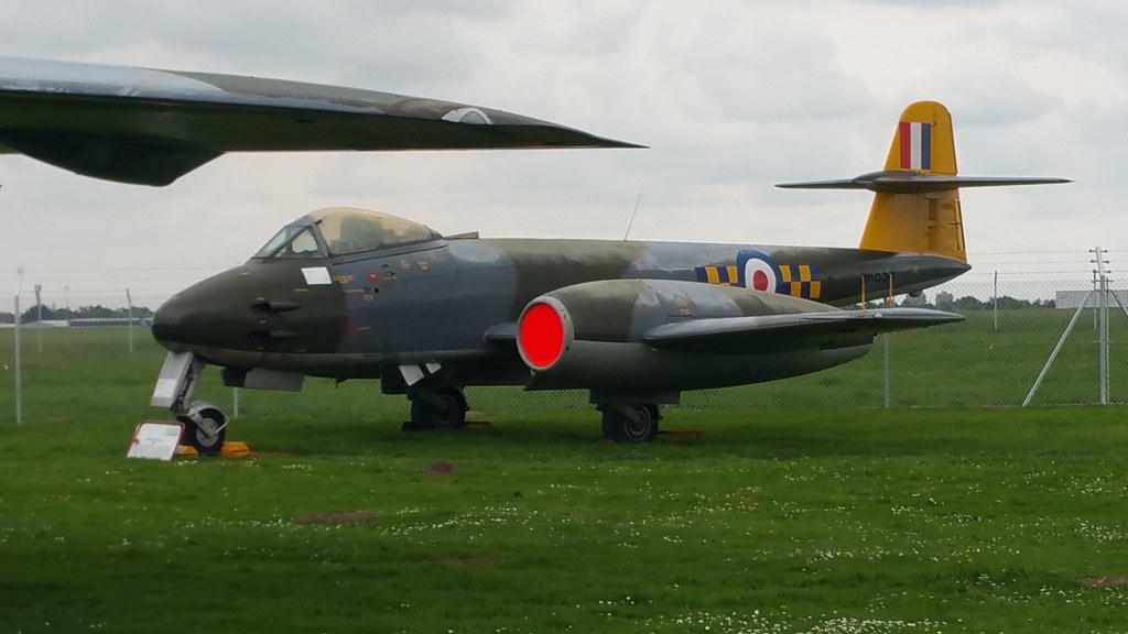
Gloster Meteor F.Mk.8 (WK654) Jet Fighter, City of Norwich Aviation Museum.
This aircraft is painted the colours of 245 Squadron based at RAF Horsham St Faith. The museum acquired the aeroplane from RAF Neatishead were it was displayed at a 'gate guard' for many years. Much of the repainting was carried out by painters from RAF Coltishall in the summer of 2005.
The RAF's main Fighter from 1950 to 1955, was the Gloster Meteor, this was Britain's first Jet Fighter, the Mk.I's were the only Allied Jet Aircraft to see operational service during World War Two, they equipped No.1 Squadron which went into action in 1944 against the German V1 Flying Bombs fired against Great Britain. The Squadron had some success but found the Meteor could not accelerate as quickly as the RAF's latest large piston engined Fighters !
Improved versions of the Meteor followed in the Post War years, the Meteor F8 entered RAF service in 1950 replacing the earlier F4's as the 'mainstay' of Fighter Command’s Home Defence Squadrons.
The Gloster Meteor was the first British Jet fighter and the Allies' only Jet Aircraft to achieve Combat Operations during World War Two. The Meteor's development was heavily reliant on its ground-breaking 'Turbojet Engines' pioneered by Frank Whittle and his company ''Power Jets Ltd''. Development of the Aircraft began in 1940, although work on the Engines had been under way since 1936. The Meteor first flew in 1943 and commenced operations on 27th July 1944 with No.616 Squadron RAF. The type was not a sophisticated Aircraft in its aerodynamics, but proved to be a successful Combat Fighter. Gloster's 1946 civil Meteor F.4 demonstrator G-AIDC was the first civilian-registered Jet Aircraft in the world. Several major variants of the Meteor incorporated technological advances during the 1940's and 1950's. Thousands of Meteors were built to fly with the RAF and other Air Forces and remained in use for several decades.
Gloster Meteors of the Royal Australian Air Force (RAAF) fought in the Korean War, several other operators such as Argentina, Egypt and Israel flew Meteor's in later regional conflicts. Specialised variants of the Meteor were developed for use in Photographic Aerial Reconnaissance and as Night Fighters. The Meteor was also used for research and development purposes and to break several aviation records and on 7th November 1945, the first official airspeed record by a Jet Aircraft was set by a Meteor F.3 at 606mph. In 1946, this record was broken when a Meteor F.4 reached a speed of 616mph. Other performance related records were broken in categories including flight time endurance, rate of climb, and speed. On 20th September 1945, a heavily modified Meteor Mk.I powered by two Rolls-Royce Trent Turbine Engines driving propellers, became the first turboprop aircraft to fly. On 10th February 1954, a specially adapted Meteor F.8, the ''Meteor Prone Pilot'' which placed the Pilot into a prone position to counteract inertial forces, took its first flight.
In the 1950's, the Meteor became increasingly obsolete as more nations introduced Jet Fighters, many of these newcomers having adopted a swept wing instead of the Meteor's conventional straight wing, in RAF service, the Meteor was replaced by newer types such as the Hawker Hunter and Gloster Javelin. As of 2018, two Meteors, G-JSMA and G-JWMA, remain in active service with the Martin-Baker Company as 'Ejection Seat Testbeds'. One further Aircraft in the UK remains airworthy, as does another in Australia.
Late in 1945, two F.3 Meteors were modified for an attempt on the world air speed record, on 7th November 1945 at Herne Bay in Kent, Group Captain Hugh ''Willie'' Wilson set the first official air speed record by a Jet Aircraft of 606mph TAS (True Airspeed) In 1946, Group Captain Edward ''Teddy'' Donaldson broke this record with a speed of 616mph TAS, in EE549, a Meteor F.4.
▪︎Role: Fighter Aircraft
▪︎National Origin: United Kingdom
▪︎Manufacturer: Gloster Aircraft Company
▪︎First Flight: 5th March 1943
▪︎Introduction: 27th July 1944
▪︎Retired: 1980s (RAF Target Tugs)
▪︎Status: Two in use as Testbed Aircraft (one with civil registration)
▪︎Primary Users: Royal Air Force / Royal Australian Air Force / Belgian Air Force / Argentine Air Force
▪︎Power Plant: Rolls-Royce RB.50 Trent
▪︎Produced: 1943 to 1955
▪︎Number Built: 3,947.
Via Flickr
2 notes
·
View notes
Text
Rolls-Royce Heads To Net Zero After Covid Turbulence.
British Jet Engines Group Seeks Greener Fuel and Battery Power Following Collapse of Long-Haul Air Travel.
On a bright September afternoon, a small silver and blue plane took off from Boscombe Down, the military airfield near Stonehenge that has been the scene of many famous maiden flights.
This was no exception: The single-seater ran on electric power and had the hopes of its developer, Rolls-Royce, of finally bringing a battery-powered aircraft to market.
With 6,000 battery cells and three motors delivering more than 500 horsepower, Spirit of Innovation (pictured above) will soon be aiming for a world air speed record for electric aircraft. But it's not just about chasing records; The aircraft is the most striking example of the FTSE 100 company's focus on developing technological advancements that could transform commercial aviation.
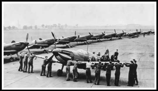
The show has echoes of one of the company's most celebrated episodes, when Rolls-Royce developed the Type R engine. It powered airspeed racers in the 1930s and was the precursor to the Merlin engine used in the Spitfire fighter jet during World War II.
1 note
·
View note
Text
Airspeed Christmas Services 2022
Airspeed Christmas Services 2022
’Tis the season to be merry! We’re down to the last two months of 2022, and it has been a colorful year for the Airspeed Group of Companies and there’s so many things to be grateful and to be ecstatic for before welcoming the new year. Starting from Airspeed’s unstoppable innovation and its vision to grow despite the challenge during the pandemic. The company strived and was considered as one…

View On WordPress
0 notes
Text
Final minutes of Air France flight AF447 to be examined as trial opens
The harrowing final minutes of the Air France flight from Rio de Janeiro to Paris that went into freefall and plunged into the Atlantic Ocean in 2009, killing all 228 people on board, will be examined as a landmark trial opens in Paris on Monday.
Two aviation industry heavyweights – the airline Air France, and the aircraft maker Airbus – are being tried on charges of involuntary manslaughter for what was the worst plane crash in the French airline’s history.
It is the first time French companies have been directly placed on trial after an air crash, rather than individuals, and families’ lawyers battled for years to bring the case to court.
The crash on 1 June 2009 shook the world of air travel when flight AF447 disappeared from radars as it crossed the night sky during a storm over the Atlantic between Brazil and Senegal. The Airbus A330 had vanished without a mayday sign.
Days later, debris was found in the ocean, but it took nearly two years to locate the bulk of the fuselage and recover the “black box” flight recorders. The unprecedented French search effort involved combing 17,000 sq km of ocean bed at depths of up to 4,000 metres for over 22 months.
The plane had been carrying 12 crew members and 216 passengers from 33 different nationalities, all of whom were killed.
Planes most often crash on land and the AF447 ocean crash came to be seen as one of a handful of accidents that changed aviation. It led to changes in safety regulations, pilot training and the use of airspeed sensors.
The trial will hear extensive detail from the final, fatal minutes in the cockpit as the confused captain and co-pilots fought to control the plane.
As the plane approached the equator on its way to Paris, it had entered a so-called “intertropical convergence zone” that often produces volatile storms with heavy precipitation. As a storm buffeted the plane, ice crystals present at high altitudes had disabled the plane’s airspeed sensors, blocking speed and altitude information. The automatic pilot functions stopped working.
The 205-tonne jet went into an aerodynamic stall and then plunged.
“We’ve lost our speeds,” one co-pilot is heard saying in the flight recordings, before other indicators mistakenly show a loss of altitude, and a series of alarm messages appear on the cockpit screens. “I don’t know what’s happening,” one of the pilots says.
The historic trial will consider the role of the airspeed sensors and the pilots.
Daniele Lamy, president of the victims’ group, Entraide et Solidarité, told AFP: “We expect an impartial and exemplary trial so that this never happens again, and that as a result the two defendants will make safety their priority instead of only profitability.”
Air France and Airbus face potential fines of up to €225,000 – a fraction of their annual revenues – but they could suffer damage to their reputations if found criminally responsible.
Both companies have denied any criminal negligence, and investigating magistrates overseeing the case dropped the charges in 2019, attributing the crash mainly to pilot error.
That decision infuriated victims’ families, and in 2021 a Paris appeals court ruled there was sufficient evidence to allow a trial to go ahead.
“Air France … will continue to demonstrate that it did not commit any criminal negligence that caused this accident, and will request an acquittal,” the airline said in a statement to AFP.
Airbus, maker of the A330 jet that had been put into service just four years before the accident, did not comment before the trial but has also denied any criminal negligence.
From Italy to Sweden, Hungary to France, the far right is once again a force to be reckoned with. Its hostility towards immigrants encourages xenophobes everywhere, including in India. Its social conservatism threatens hard-won LGBTQ+ rights. Its euroscepticism has already upset the dynamics of the EU.

The normalisation of far right rhetoric has gone far enough. For decades, Guardian journalism has challenged populists like this, and the divisions that they sow. Fiercely independent, we are able to confront without holding back because of the interests of shareholders or a billionaire owner. Our journalism is always free from commercial or political influence. Reporting like this is vital for democracy, for fairness and to demand better from the powerful.
And we provide all this for free, for everyone to read. We do this because we believe in information equality. Greater numbers of people can keep track of the events shaping our world, understand their impact on people and communities, and become inspired to take meaningful action. Millions can benefit from open access to quality, truthful news, regardless of their ability to pay for it.
Every contribution, however big or small, powers our journalism and sustains our future.
0 notes
Text
Best Flight Simulator For Mac Os X

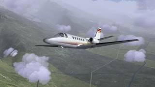
A good flight simulator is the one which have realistic graphics, real maps, best in class airplanes and controls that can simulate a real flying experience. In this article, we are going to list the top free flight simulator that one can use to fly their favorite aircraft with amazingly real graphics. The Covid-19 lockdown around the world can be very tiring for a lot of us, hence we have some amazing free flight simulator for you to try. We have earlier posted an article on fastest aircraft in GeoFS (Geo Flight Simulator) and now we are here with a lot more for you.
In this list we are going to list some flight simulators which come in two categories, ONLINE FLIGHT SIMULATOR and FREE FLIGHT SIMULATOR. We tried our best to research and list only those flight simulators that are good and easily accessible.
What is a flight simulator?
5 Flight Simulator for MAC OS. After How To Use Flight Simulator now here are Top 5 Flight Simulator for MAC OS. The simulators which are given down below are all based on their performance, reviews from gamers and experts. If you know better simulators from this, will be happy to hear from you. Checkout Top 5 Overwatch Mods Minecraft. GeoFS (GEO FLIGHT SIMULATOR) This is the first and best online flight simulator in our list.
A flight simulator is an artificial flight environment where you can recreate a flying experience. Flight simulators are used by companies to train the future pilots and to enhance their flying skills. A flight simulator is not just for fun but is also used to recreate an air crash to know the reasons for it. Air crash investigations are carried out in which they recreate the flight with the provided data to look for various reasons of the crash. In this article, we will only talk about a basic flight simulator which you can use for fun and to fulfill your dreams of flying any aircraft.
Microsoft Flight Simulator X Mac
List of top free flight simulator of 2020
Below we are listing the best flight simulators. You can access all of them for free and they have been tested according to the users needs. We will provide the direct links to access these free flight simulator if they are available.
1. GeoFS (GEO FLIGHT SIMULATOR)
This is the first and best online flight simulator in our list. GeoFS was earlier Google Earth Flight Simulator but later google discontinued it. The GeoFS community was so impressed by the flight simulator that they decided to continue it and it is now owned by Cesium webGL. You can access this flight simulator directly through your web browser anytime and anywhere, GeoFS does not require any files to be downloaded. GeoFS have many features which gives us the best flying experience. There is a huge list of available aircraft that you can fly like the Airbus A380, Boeing 747, Airbus A350 and also the spersonic F16.
Features of GeoFS
Real map- GeoFS has a real map that means you can fly anywhere around the globe and land or takeoff from any airport.
HD graphics- GeoFS have stunning graphics and smooth runways.
Real time weather conditions- The free flight simulator has an amazing feature through which you can experience real time weather of any place and also real time airspeed which makes it even more realistic.
There are a total of 40 aircraft which you can fly in GeoFS. these 40 aircraft include commercial aircraft, supersonic jets, helicopter, hot air balloon and even a glider.
Multiplayer GeoFS is a multiplayer flight simulator which means you can fly with your friends and do a group flight.
Free of cost- GeoFS provides all these features for free and does not charge anything.
Where can I use the GeoFS?
One can use the GeoFS on any web browser and does not need to download any files to your computer. GeoFS is now also available on your Android Mobile devices and iOS. The links are provided below.
web browser link – GeoFS
Android App- GeoFS Android App Avatar the last airbender game download pc.
iOS app- GeoFS iOS app
ALSO CHECK
2. Flight Gear (Windows, MacOS)
Flight Gear is another stunning free flight simulator that is supported on windows and MacOS. This is the advanced level of GeoFS where the controls and graphics are even more realistic and smooth. Flight Gear is owned by Microsoft and was started in 1997. Since then this amazing free flight simulator has been improvised by the developer community. Flight Gear is an open source software which means installation can be a little confusing for some. There is a large variety of aircraft to fly that are community contributed which you will have to install manually. but in case you face a problem configuring these aircraft, you can still fly a Cessna 172 and enjoy the large map of the simulator. Below we will be listing the features of Flight Gear and provide you a few important links.
Features of Flight Gear
free of cost- The main feature is obviously the fact that Flight Gear is totally free of cost, you do not have to buy it from anywhere.
Huge map and tons of airports- Flight Gear offers the pilots a lot of airports that are approximately 20,000 till date. It also has a huge map to fly.
Stunning graphics- Flight Gear have some very realistic graphics, one can adjust the graphics according to there needs, the system requirements are not too high as well.
detailed weather effects.
open source software.
Download FlightGear 2018.3.5 for Windows (versions 7, 8, 10)
Download FlightGear 2018.3.5 for macOS
download additional aircraft here.
Vlc player for mac os x 10 6 8. Download the latest World Scenery data updates.
Visit the FlightGear store.
X-Plane 11 (Windows, MacOS, Linux, Android, iOS)
Laminar Research’s X-Plane 11 is another flight simulator that has a different fan base. Its a free flight simulator and have more than 3000 airports with realistic hangers where you can park your aircraft and terminal buildings. It is not just another flight simulator as it have very real controls and is very detailed. The developers who made it claim that it is not just a simulation game but a lot more than that since it is very realistic. It offers very accurate detailing of the aircraft and the maps, multiplayer option offers you an ATC (Air Traffic Controller) which makes it even more impressive. X-Plane have some serious controls which may be difficult to understand for some, but for those aviation enthusiasts who want a totally real flying experience, X-Plane 11 is just for you.
Best Flight Simulator For Mac Os X 10.13
unfortunately the full version is not free but you can download the demo version and enjoy it, we will provide the link below. Bluestacks 1 root.
Features of X-Plane 11
Microsoft Flight Simulator For Mac Os X
Realistic Graphics
3000 Airports
Realistic Cockpit View
Large Variety of Aircraft
Available on almost every platform.
Free demo version available.

Hope you liked these top free flight simulator that are listed in our article. We suggest you to try each and all of them. Also share your views with us in the comment section below. Minitool partition wizard 12.1 key.
0 notes
Text
Managing Control Forces.
Managing Control Forces. As airplanes evolved from stick and wire contraptions to awesome supersonic machines, the pilot at the center of it all has not changed. Desirable maximum and minimum levels of pilot stick, yoke, and rudder pedal control forces required to steer and maneuver are much the same, but the engineering solutions that bring these forces about have changed with the times. Desirable Control Force Levels. In 1936 and 1937, NACA research pilots and engineers Melvin N. Gough, A. P. Beard, and William H. McAvoy used an instrumented cockpit to establish maximum force levels for control sticks and wheels. In lateral control the maximums for one hand are 30 pounds applied at a stick grip and 80 pounds applied at the rim of a control wheel. In longitudinal control the maximums are 35 pounds for a stick and 50 pounds for a wheel. Lower forces are desirable and easily attainable with modern artificial feel systems. The Federal Aviation Administration allows higher forces for transport-category airplanes under FAR Part 25. Seventy-five pounds is allowed for temporary application. However, the data compilation for the handbook accompanying MIL-STD-1797, a current military document, shows that a little over 50 percent of male pilots and fewer than 5 percent of female pilots are capable of this force level. Gough-Beard-McAvoy force levels are generally used as maximum limits for conventional stick, yoke, and rudder pedal controllers, but much lower control force levels are specified for artificial-feel systems and for side-stick controls operated by wrist and forearm motions. Background to Aerodynamically Balanced Control Surfaces. When airplanes and their control surfaces became large and airplane speeds rose to several hundred miles per hour, control forces grew to the point where even the Gough Beard-McAvoy force limits were exceeded. Pilots needed assistance to move control surfaces to their full travels against the pressure of the air moving past the surfaces. An obvious expedient was to use those same pressures on extensions of the control surface forward of the hinges, to balance the pressure forces that tried to keep the control surfaces faired with the wing. The actual developmental history of aerodynamically balanced control surfaces did not proceed in a logical manner. But a logical first step would have been to establish a background for design of the balances by developing design charts for the forces and hinge moments for unbalanced control surfaces. That step took place first in Great Britain. Glauert’s calculations were based on thin airfoil theory. W. G. Perrin followed in the next year with the theoretical basis for control tab design. The next significant step in the background for forces and hinge moments for unbalanced control surfaces was NACA pressure distribution tests on a NACA 0009 airfoil, an airfoil particularly suited to tail surfaces. The trends with control surface hinge position along the airfoil chord match Glauert’s thin airfoil theory exactly, but with lower flap effectiveness and hinge moment than the theoretical values. Ames and his associates developed a fairly complex scheme to derive three-dimensional wing and tail surface data from the two-dimensional design charts. That NACA work was complemented for horizontal tails by a collection of actual horizontal tail data for 17 tail surfaces, 8 Russian and 3 each Polish, British, and U.S. Full control surface design charts came later, with the publication of stability and control handbooks in several countries. Horn Balances. The first aerodynamic balances to have been used were horn balances, in which area ahead of the hinge line is used only at the control surface tips. In fact, rudder horn balances appear in photos of the Moisant and Bleriot XI monoplanes of the year 1910. It is doubtful that the Moisant and Bl´eriot horn balances were meant to reduce control forces on those tiny, slow airplanes. However, the rudder and aileron horn balances of the large Curtiss F-5L flying boat of 1918 almost certainly had that purpose. Wind-tunnel measurements of the hinge moment reductions provided by horn balances show an interesting characteristic. Control surface hinge moments arise from two sources: control deflection with respect to the fixed surface and angle of attack of the fixed or main surface. The relationship is given in linearized dimensionless form by the equation hinge moment coefficient equals to the derivative of the hinge moment coefficient with respect to the control surface deflection times control surface deflection with respect to the fixed surface plus the derivative of the hinge moment coefficient with respect to angle of attack of the fixed or main surface times the angle of attack of the fixed or main surface, where the hinge moment coefficient is the hinge moment divided by the surface area and mean chord aft of the hinge line and by the dynamic pressure. Both derivatives are normally negative in sign. A negative derivative of the hinge moment coefficient with respect to the control surface deflection means that when deflected the control tends to return to the faired position. A negative derivative of the hinge moment coefficient with respect to angle of attack of the fixed or main surface means that when the fixed surface takes a positive angle of attack the control floats upward, or trailing edge high. Upfloating control surfaces reduce the stabilizing effect of the tail surfaces. It was discovered that horn balances produce positive changes in the derivative of the hinge moment coefficient with respect to angle of attack of the fixed or main surface, reducing the up floating tendency and increasing stability with the pilot’s controls free and the control surfaces free to float. This horn balance advantage has to be weighed against two disadvantages. The aerodynamic balancing moments applied at control surface tips twist the control surface. Likewise, flutter balance weights placed at the tips of the horn, where they have a good moment arm with respect to the hinge line, lose effectiveness with control surface twist. A horn balance variation is the shielded horn balance, in which the horn leading edge is set behind the fixed structure of a wing or tail surface. Shielded horn balances are thought to be less susceptible to accumulating leading-edge ice. Shielded horn balances are also thought to be less susceptible to snagging a pilot’s parachute lines during bailout. Overhang or Leading-Edge Balances. When control surface area ahead of the hinge line is distributed along the span of the control surface, instead of in a horn at the tip, the balance is called an overhang or a leading-edge balance. Overhang design parameters are the percentage of area ahead of the hinge line relative to the total control surface area and the cross-sectional shape of the overhang. Experimental data on the effects of overhang balances on hinge moments and control effectiveness started to be collected as far back as the late 1920s. Some of these early data are given by Abe Silverstein and S. Katzoff. Airplane manufacturers made their own correlations of the effects of overhang balances, notably at the Douglas Aircraft Company. As in many other disciplines, the pressure of World War II accelerated these developments. Root and his group at Douglas found optimized overhang balance proportions for the SBD-1 Dauntless dive bomber by providing for adjustments on hinge line location and overhang nose shape on the SBD-1 prototype, known as the XBT-2. Root wrote a NACA Advance Confidential Report in May 1942 to document a long series of control surface and other modifications leading to flying qualities that satisfied Navy test pilots. For example, in 1 of 12 horizontal tail modifications that were flight tested, the elevator overhang was changed from an elliptical to a “radial,” or more blunt, cross-section, to provide more aerodynamic balancing for small elevator movements. This was to reduce control forces at high airspeeds. Overhang aerodynamic balance, in combination with spring tabs, continue in use in Douglas transport airplanes, from the DC-6 and DC-7 series right up to the elevators and ailerons of the jet-powered DC-8. The DC-8’s elevator is balanced by a 35-percent elliptical nose overhang balance. Remarkably constant hinge moment coefficient variations with elevator deflection are obtained up to a Mach number of 0.96. George S. Schairer came to the Boeing Company with an extensive control surface development background at Convair and in the Cal Tech GALCIT 10-foot wind tunnel. Although early B-17s had used spring tabs, Schairer decided to switch to leading-edge balances for the B-17E and the B-29 bombers. The rounded nose overhang balances on the B-29s worked generally well, except for an elevator overbalance tendency at large deflection angles. Large elevator angles were used in push-overs into dives for evasive action. William Cook remarks, “A World War II B-29 pilot friend of mine was quite familiar with this characteristic, so the fact that he got back meant this must have been tolerable.” However, overhang balance was not effective for the B-29 ailerons. Forces were excessive. The wartime and other work on overhang aerodynamic balance was summarized by the NACA Langley Research Department. The Toll report remains a useful reference for modern stability and control designers working with overhang aerodynamic balances and other aerodynamic balance types as well. Frise Ailerons. The hinge line of the Frise aileron, invented by Leslie George Frise, is always at or below the wing’s lower surface. If one sees aileron hinge brackets below the wing, chances are that one is looking at a Frise aileron. Frise ailerons were used on many historic airplanes after the First World War, including the Boeing XB-15 and B-17, the Bell P-39, the Grumman F6F-3 and TBF, and the famous World War II opponents – the Spitfire, Hurricane, and Focke-Wulf 190 fighters. Frise ailerons were applied to both the Curtiss-Wright C-46 Commando and the Douglas C-54 Sky master during World War II, to replace the hydraulic boost systems used in their respective prototypes. With the hinge point below the wing surface, an arc drawn from the hinge point to be tangent to the wing upper surface penetrates the wing lower surface some distance ahead of the hinge line, thus establishing an overhang balance. The gap between the aileron and wing can be made as narrow as desired by describing another arc slightly larger than the first. This in fact is typical of the Frise aileron design. The narrow wing-to-aileron gap reduces air flow from the high-pressure wing under surface to the lower pressure wing upper surface, reducing drag. The Frise aileron is less prone to accumulate ice for that same reason. It was promoted by the U.S. Army Air Corps Handbook for Airplane Designers as an anti-icing aileron. The relatively sharp Frise aileron nose develops high velocities and low static pressures when projecting below the wing lower surface, when the aileron goes trailing-edge up. This generally overbalances the up-going aileron. On the other hand, the overbalanced-up aileron is connected by control cables or pushrods to the down-going aileron on the other side of the wing. The sharp Frise nose on that side is within the wing contour; the down aileron is underbalanced. By connecting the up and down sides through the pilot’s controls the combination is made stable, with lowered control forces relative to ailerons without aerodynamic balance. The sharp nose of the Frise aileron, protruding below the wing’s lower surface for trailing edge-up deflections, has been thought to help reduce adverse yaw when rolling. The trailing edge-up aileron is on the down-going wing in a roll. In adverse yaw, the down-going wing moves forward, while the airplane yaws in a direction opposite to that corresponding to a coordinated turn. Flow separation from the Frise aileron sharp nose is supposed to increase drag on the down-going wing, pulling it back and reducing adverse yaw. This happens to some extent, but for normal wing plan forms with aspect ratios above about 6, adverse yaw is actually dominated by the aerodynamic yawing moment due to rolling, and is little affected by Frise ailerons. Adverse yaw must be overcome by good directional stability complemented by rudder deflection in harmony with aileron deflection. A Frise aileron design used on the Douglas SBD-1 Dauntless. This design was the seventh and final configuration tested in 1939 and 1940. Nose shape, wing-to-aileron gap, hinge line position, and gap seal parameters were all varied. Flight test evidence of Frise aileron oscillations on a Waco XCG-3 glider due to alternate stalling and unstalling of the sharp nose at extreme up-aileron travels. The upper photo shows the bulky roll rate recorder. The lower photo is a rate of roll trace for two abrupt full aileron rolls. Aileron oscillations are shown by the ripples at the peak roll rate values. Frise ailerons turned out to have problems on large airplanes, where there is a long cable run from the control yoke to the ailerons. In the development of the Waco XCG-3 glider in 1942, the sharp nose of its Frise ailerons alternately stalled and unstalled when the ailerons were held in a deflected position. This created severe buffeting. The aileron nose stalled at the largest angle, reducing the balancing hinge moment. Control cable stretch allowed the aileron to start back toward neutral. But as the aileron angle reduced the nose unstalled, the aerodynamic balance returned, and the aileron started back toward full deflection, completing the cycle. The fix for the XCG-3 was to limit up-aileron angles from 30 to 20 degrees and to round off the sharp nose to delay stalling of the nose. Modified Frise ailerons, with noses raised to delay stalling, had been tested in Britain by A. S. Hartshorn and F. B. Bradfield as early as 1934. The advantages of raised-nose Frise ailerons were verified in NACA tests on a Curtiss P-40. Beveled trailing edges were added to the raised-nose Frise ailerons on the P-40, to make up for loss in aerodynamic balance at small deflections. Lateral stick force remained fairly linear and very low up to a total aileron deflection of 48 degrees, giving a remarkably high dimensionless roll rate of 0.138 at 200 miles per hour. Aileron Differential. The larger travel of one aileron relative to the other is called aileron differential. Aileron differential is a method of reducing control forces by taking advantage of hinge moment bias in one direction. At positive wing angles of attack, the hinge moment acting on both ailerons is normally trailing-edge up, and we say the ailerons want to float up. Assume that the up-going aileron is given a larger travel than the down-going aileron for a given control stick or wheel throw. Then, the work done by the trailing-edge-up hinge moment acting on the up-going aileron can be nearly as great as the work the pilot does in moving the down-going aileron against its up-acting hinge moment, and little pilot force is needed to move the combination. The differential appropriate for up-float is more trailing-edge-up angle than down. Typical values are 30 degrees up and 15 degrees down. The floating hinge moment can be augmented, or even reversed, by fixed tabs. Aileron up-float, associated with negative values of the hinge moment derivative, is greatest at high wing angles of attack. Neglecting accelerated flight, high wing angles of attack occur at low airspeeds. Thus, aileron differential has the unfortunate effect of reducing aileron control forces at low airspeeds more than at high airspeeds, where reductions are really needed. In addition to the force-lightening characteristic of aileron differential, increased up relative to down aileron tends to minimize adverse yaw in aileron rolls, which is the tendency of the nose to swing initially in the opposite direction to the commanded roll. Adverse yaw in aileron rolls remains a problem for modern airplanes, especially those with low directional stability, such as tailless airplanes. Where stability augmentation is available, it is a more powerful means of overcoming adverse yaw than aileron differential. Balancing or Geared Tabs. Control surface tabs affect the pressure distribution at the rear of control surfaces, where there is a large moment arm about the hinge line. A trailing-edge-up tab creates relative positive pressure on the control’s upper surface and a relative negative pressure peak over the tab-surface hinge line. Both pressure changes drive the control surface in the opposite direction to the tab, or trailing-edge-down. When a tab is linked to the main wing so as to drive the tab in opposition to control surface motion, it is called a balancing or geared tab. Balancing tabs are used widely to reduce control forces due to control surface deflection. They have no effect on the hinge moments due to wing or tail surface angle of attack. Airplanes with balancing tabs include the Lockheed Jet star rudder, the Bell P-39 ailerons, and the Convair 880M. Trailing-Edge Angle and Beveled Controls. The included angle of upper and lower surfaces at the trailing edge, or trailing edge angle, has a major effect on control surface aerodynamic hinge moment. This was not realized by practicing stability and control engineers until well into the World War II era. For example, a large trailing-edge angle is now known to be responsible for a puzzling rudder snaking oscillation experienced in 1937 with the Douglas DC-2 airplane. Quoting from an internal Douglas Company document of July 12, 1937, by L. Eugene Root: The first DC-2s had a very undesirable characteristic in that, even in smooth air, they would develop a directional oscillation. In rough air this characteristic was worse, and air sickness was a common complaint.... It was noticed, by watching the rudder in flight, that during the hunting the rudder moved back and forth keeping time with the oscillations of the airplane. It is common knowledge that the control surfaces were laid out along airfoil lines. Because of this fact, the rearward portion of the vertical surface, or the rudder, had curved sides. It was thought that these curved sides were causing the trouble because of separation of the air from the surface of the rudder before reaching the trailing edge. In other words, there was a region in which the rudder could move and not hit “solid” air, thus causing the movement from side to side. The curvature was increased towards the trailing edge of the rudder in such a way as to reduce the supposedly “dead” area.... The change that we made to the rudder was definitely in the wrong direction, for the airplane oscillated severely.... After trying several combinations on both elevators and rudder, we finally tried a rudder with straight sides instead of those which would normally result from the use of airfoil sections for the vertical surfaces. We were relieved when the oscillations disappeared entirely upon the use of this type of rudder. The Douglas group had stumbled on the solution to the oscillation or snaking problem, reduction of the rudder floating tendency through reduction of the trailing-edge angle. Flat sided control surfaces have reduced trailing-edge angles compared with control surfaces that fill out the airfoil contour. We now understand the role of the control surface trailing edge angle on hinge moments. The wing’s boundary layer is thinned on the control surface’s windward side, or the wing surface from which the control protrudes. Conversely, the wing’s boundary layer thickens on the control surface’s leeward side, where the control surface has moved away from the flow. Otherwise stated, for small downward control surface angles or positive wing angles of attack the wing’s boundary layer is thinned on the control surface bottom and thickened on the control’s upper surface. The effect of this differential boundary layer action for down-control angles or positive wing angles of attack is to cause the flow to adhere more closely to the lower control surface side than to the upper side. In following the lower surface contour the flow curves toward the trailing edge. This curve creates local suction, just as an upward-deflected tab would do. On the other hand, the relatively thickened upper surface boundary layer causes the flow to ignore the upper surface curvature. The absence of a flow curve around the upper surface completes the analogy to the effect of an upward-deflected tab. The technical jargon for this effect is that large control surface trailing-edge angles create positive values of the derivative of the hinge moment coefficient with respect to the control surface deflection and the derivative of the hinge moment coefficient with respect to angle of attack of the fixed or main surface, which are , the floating and restoring derivatives, respectively. The dynamic mechanism for unstable lateral-directional oscillations with a free rudder became known on both sides of the Atlantic a little after the Douglas DC-2 experience. Unstable yaw oscillations were calculated in Britain for a rudder that floated into the wind. This was confirmed in two NACA studies. The aerodynamic connection between trailing-edge angle and control surface hinge moment, including the floating tendency, completed the story. Following the success of the flat-sided rudder in correcting yaw snaking oscillations on the Douglas DC-2, flat-sided control surfaces became standard design practice on Douglas airplanes. William H. Cook credits George S. Schairer with introducing flat-sided control surfaces at Boeing, where they were used first on the B-17E and B-29 airplanes. Trailing edge angles of fabric-covered control surfaces vary in flight with the pressure differential across the fabric. A Douglas C-74 transport was lost in 1946 when elevator fabric bulging between ribs increased the trailing-edge angle, causing pitch oscillations that broke off the wing tips. C-74 elevators were metal-covered after that. Understanding of the role of the trailing-edge angle in aerodynamic hinge moments opened the way for its use as another method of control force management. Beveled control surfaces, in which the trailing-edge angle is made arbitrarily large, is such an application. Beveled control surfaces, a British invention of World War II vintage, work like balancing tabs for small control surface angles. The beveled-edge control works quite well for moderate bevel angles. As applied to the North American P-51 Mustang, beveled ailerons almost doubled the available rate of roll at high airspeeds, where high control forces limit the available amount of aileron deflection. But large bevel angles, around 30 degrees, acted too well at high Mach numbers, causing overbalance and unacceptable limit cycle oscillations. Beveled controls have survived into recent times, used for example on the ailerons of the Grumman/Gulfstream AA-5 Tiger and on some Mooney airplanes. Corded Controls. Corded controls, apparently invented in Britain, are thin cylinders, such as actual cord, fastened to control surfaces just ahead of the trailing edge. They are used on one or both sides of a control surface. Corded controls are the inverse of beveled controls. Bevels on the control surface side that projects into the wind produce relative negative pressures near the bevel that balance the control aerodynamically, reducing operating force. On the other hand, cords on the control surface side that projects into the wind create local positive pressures on the surface just ahead of the cord. This increases control operating force. Cords on both sides of a control surface are used to eliminate aerodynamic overbalance. On one side they act as a fixed trim tab. Very light control forces have been achieved by cut and try by starting with aerodynamically overbalanced surfaces, caused by deliberately oversized overhang balances. Quite long cords correct the overbalance, providing stable control forces. In the cut and try process the cords are trimmed back in increments until the forces have been lightened to the pilot’s or designer’s satisfaction. Adjustable projections normal to the trailing edge, called Gurney flaps, act as one-sided cord trim tabs. Spoiler Ailerons. Spoiler ailerons project upward from the upper surface of one wing, reducing lift on that wing and thus producing a rolling moment. Spoiler ailerons are often the same surfaces used symmetrically to reduce lift and increase drag on large jet airplanes for rapid descents and to assist braking on runways. Spoiler ailerons are generally used either to free wing trailing edges for full-span landing flaps or to minimize wing twist due to aileron action on very flexible wings. The aerodynamic details of spoiler operation are still not completely understood, even after years of experiment and theoretical studies. The aerodynamics of a rapidly opened spoiler has two phases, the opening and steady-state phases. Experimental or wind-tunnel studies of rapidly opening upper-wing surface spoilers show a momentary increase in lift, followed by a rapid decrease to a steady-state value that is lower than the initial value. At a wind speed of 39 feet per second, the initial increase is over in less than a half-second, and steady-state conditions appear in about 3 seconds. Results from the computational fluid dynamics method known as the discrete vortex method also predict the momentary increase in lift and associate it with a vortex shed from the spoiler upper edge in a direction that increases net airfoil circulation in the lifting direction. A subsequent shed vortex from the wing trailing edge in the opposite direction reduces circulation to the steady-state value. While suggestive, experimental flow visualization results do not exist that confirm this vortex model. The Yeung, Xu, and Gu experiments show that providing small clearances between the spoiler lower edge and the wing upper surface reduces the momentary increase in lift following spoiler extension. This is consistent with a small shed vortex from the spoiler lower edge of opposite rotation to the vortex shed at the upper edge. A clearance between spoiler and wing surface of this type has also been used to reduce buffet. Separation behind an opened spoiler on a wing upper surface causes distortion of the external or potential flow that is similar to the effect of a flap-type surface with trailing-edge-up deflection. In the latter case, streamlines above the wing are raised toward the wing trailing edge. The effective wing camber is negative in the trailing-edge region, causing a net loss in circulation and lift. The difference in the two cases is that the effective wing trailing edge in the spoiler case is somewhere in the middle of the separated region, instead of at the actual trailing edge, as in the flap-type surface case. The hinge moments of ordinary hinged-flap and slot lip spoiler ailerons are high; brute hydraulic force is used to open them against the airstream. Retractable arc and plug spoiler ailerons are designed for very low hinge moments and operating forces. Although aerodynamic pressures on the curved surfaces of these ailerons are high, the lines of action of these pressures are directed through the hinge line and do not show up as hinge moments. Hinge moments arise only from pressure forces on the ends of the arcs and from small skin friction forces on the curved surfaces. A very early application of plug ailerons was to the Northrop P-61 Black Widow, which went into production in 1943. The P-61 application illustrates the compromises that are needed at times when adapting a device tested in a wind tunnel to an actual airplane. The plug aileron is obviously intended to work only in the up position. However, it turned out not to be possible to have the P-61 plug ailerons come to a dead stop within the wing when retracting them from the up position. The only practical way to gear the P-61 plug ailerons to the cable control system attached to the wheel was by extreme differential. Full up-plug aileron extension on one side results in a slight amount of down-plug aileron angle on the other side. The down-plug aileron actually projects slightly from the bottom surface of the wing. Down-plug aileron angles are shielded from the airstream by a fairing that looks like a bump running span wise. Plug-type spoiler ailerons are subject to nonlinearities in the first part of their travel out of the wing. Negative pressures on the wing’s upper surface tend to suck the plugs out, causing control overbalance. Centering springs may be needed. There can be a small range of reversed aileron effectiveness if the flow remains attached to the wing’s upper surface behind the spoiler for small spoiler projections. Nonlinearities at small deflections in the P-61 plug ailerons were swamped out by small flap-type ailerons, called guide ailerons, at the wing tips. Early flight and wind-tunnel tests of spoilers for lateral control disclosed an important design consideration, related to their chord wise location on the wing. Spoilers located about mid-chord are quite effective in a static sense but have noticeable lags. That is, for a forward-located spoiler, there is no lift or rolling moment change immediately after an abrupt up-spoiler deflection. Since airfoil circulation and lift are fixed by the Kutta trailing edge condition, the lag is probably related to the time required for the flow perturbation at the forward-located spoiler to reach the wing trailing edge. Spoilers at aft locations, where flap-type ailerons are found, have no lag problems. Another spoiler characteristic was found in early tests that would have great significance when aileron reversal became a problem. Spoiler deflections produce far less wing section pitching moment for a given lift change than ordinary flap-type ailerons. The local section pitching moment produced by ailerons twists the wing in a direction to oppose the lift due to the aileron. This is why spoilers are so common as lateral controls on high-aspect ratio wing airplanes. Open slot-lip spoilers on the Boeing 707. Note the exposed upper surface of the first element of the flaps. The open spoilers destroy the slot that ordinarily directs the flow over the flap upper surface, reducing flap effectiveness. The reduced lift improves lateral control power when the spoilers are used asymmetrically or the airplane’s braking power when deployed symmetrically on when the ground. Slot-lip spoiler ailerons are made by hinging the wing structure that forms the upper rear part of the slot on slotted landing flaps. Since a rear wing spar normally is found just ahead of the landing flaps, hinging slot-lip spoilers and installing hydraulic servos to operate them is straightforward. There is a gratifying amplification of slot-lip spoiler effectiveness when landing flaps are lowered. The landing flap slot is opened up when the slot-lip spoiler is deflected up, reducing the flap’s effectiveness on that side only and increasing rolling moment. Internally Balanced Controls. Another control surface balance type that appeared about the same time as beveled controls was the internally balanced control. This control is called the Westland-Irving internal balance in Great Britain. Internally balanced controls are intended to replace the external aerodynamic balance, a source of wing drag because of the break in the wing contour. In the internally balanced control the surface area ahead of the hinge line is a shelf contained completely within the wing contour. Unless the wing is quite thick and has its maximum thickness far aft, mechanical clearance requires either that the shelf be made small, restricting the available amount of aerodynamic balance, or control surface throws be made small, restricting effectiveness. By coincidence, internally balanced controls appeared about the same time as the NACA 65-, 66-, and 67-series airfoil sections. These are the laminar flow airfoils of the 1940s and 1950s. Internally balanced ailerons are natural partners of laminar flow airfoil sections, since aerodynamic balance is obtained without large drag-producing surface cutouts for the overhang. Not only that, but the 66 and 67 series have far aft locations of wing maximum thickness. This helps with the clearance problem of the shelf inside of the wing contour. An internal balance modification that gets around the mechanical clearance problem on thin airfoils is the compound internal balance. The compound shelf is made in two, or even three, hinged sections. The forward edge of the forward shelf section is hinged to fixed airplane structure, such as the tail or wing rear spar. The first application of the compound internal balance appears to have been made by William H. Cook, on the Boeing B-47 Stratojet. Internally balanced elevators and the rudder of the Boeing B-52 have compound shelves on the inner sections of the control surfaces and simple shelves on the outer sections. Compound internal balances continue to be used on Boeing jets, including the 707, 727, and 737 series. The 707 elevator is completely dependent on its internal aerodynamic balance; there is no hydraulic boost. According to Cook, in an early Pan American 707, an inexperienced co-pilot became disoriented over Gander, New found land, and put the airplane into a steep dive. The pilot, Waldo Lynch, had been aft chatting with passengers. He made it back to the cockpit and recovered the airplane, putting permanent set into the wings. In effect, this near-supersonic pullout proved out the 707’s manual elevator control. The 707’s internally balanced ailerons are supplemented by spoilers. The later Boeing 727 used dual hydraulic control on all control surfaces, but internal aerodynamic balance lightens control forces in a manual reversion mode. An electrically driven adjustable stabilizer helps in manual reversion. At least one 727 lost all hydraulic power and made it back using manual reversion. Internally balanced controls were used on a number of airplanes of the 1940s and 1950s. The famous North American P-51 Mustang had internally balanced ailerons, but they were unsealed, relying on small clearances at the front of the shelf to maintain a pressure differential across the shelf. The Curtiss XP-60 and Republic XF-12 both used internally balanced controls, not without operational problems on the part of the XP-60. Water collected on the seal, sometimes turning to ice. Flying or Servo and Linked Tabs. Orville R. Dunn gave 30,000 pounds as a rule-of-thumb upper limit for the weight of transport airplanes using leading-edge aerodynamic balance. Dunn considered that airplanes larger than that would require some form of tab control, or else hydraulically boosted controls. The first really large airplane to rely on tab controls was the Douglas B-19 bomber, which flew first in 1941. The B-19 used pure flying or servo tab control on the rudder and elevator and a plain-linked tab on the ailerons. In a flying tab the pilot’s controls are connected only to the tab itself. The main control surfaces float freely; no portion of the pilot’s efforts go into moving them. A plain-linked tab on the other hand divides the pilot’s efforts in some proportion between the tab and the main surface. The rudder of the Douglas C-54 Sky master transport uses a linked tab. Roger D. Schaufele recalls some anxious moments at the time of the B-19’s first flight out of Clover Field, California. The pilot was Air Corps pilot Stanley Olmstead, an experienced hand with large airplanes. This experience almost led to disaster, as Olmstead “grabbed the yoke and rotated hard” at liftoff, as he had been accustomed to doing on other large airplanes. With the flying tab providing really light elevator forces, the B-19 rotated nose up to an estimated 15 to 18 degrees, in danger of stalling, before Olmstead reacted with forward control motion. Flying tabs are quite effective in allowing large airplanes to be flown by pilot effort alone, although the B-19 actually carried along a backup hydraulic system. A strong disadvantage is the lack of control over the main control surfaces at very low airspeeds, such as in taxi, the early part of takeoffs, and the rollout after landing. The linked tab is not much better in that the pilot gets control over the main surface only after the tab has gone to its stop. Still, by providing control for the B-19, the world’s largest bomber in its time, flying and linked tabs, and the Douglas Aircraft Company engineers who applied them, deserve notice in this history. An apocryphal story about the B-19 flying tab system illustrates the need for a skeptical view of flying tales. MIT’s Otto Koppen was said to have told of a B-19 vertical tail fitted to a B-23 bomber, an airplane the size of a DC-3, to check on the flying tab scheme. The point of the story is that the B-23 flew well with its huge vertical tail. Koppen said this proved that a vertical tail could not be made too large. Unfortunately, this never occurred. Orville Dunn pointed out that the B-23 came years after the B-19, and it didn’t happen. Spring Tabs. Spring tabs overcome the main problem of flying tabs, which do not provide the pilot with control of the main surface at low speeds, as when taxiing. In spring tabs, the pilot’s linkage to the tab is also connected to the main surface through a spring. If the spring is quite stiff, good low-speed surface control results. At the same time, a portion of the pilot’s efforts goes into moving the main surface, increasing controller forces. Spring tabs have the useful feature of decreasing control forces at high airspeeds, where control forces usually are too heavy, more than at low airspeeds. At low airspeeds, the spring that puts pilot effort into moving the main surface is stiff relative to the aerodynamic forces on the surface; the tab hardly deflects. The reverse happens at high airspeeds. At high airspeeds the spring that puts pilot effort into moving the main surface is relatively weak compared with aerodynamic forces. The spring gives under pilot load; the main surface moves little, but the spring gives, deflecting the tab, which moves the main surface without requiring pilot effort. The earliest published references to spring tabs appeared as Royal Air craft Establishment publications. NACA publications followed. But the credit for devising a generalized control tab model that covers all possible variations belongs to Orville R. Dunn. The Dunn model uses three basic parameters to characterize spring tab variations, which include the geared tab, the flying tab, the linked tab, and the geared spring tab. Although the derivation of pilot controller force equations for the different tab systems involve only statics and the virtual work principle, the manipulations required are surprisingly complex. As is typical for engineering papers prepared for publication, Dunn provides only bare outlines of equation derivations. Readers of the 1949 Dunn paper who want to derive his final equations should be prepared for some hard labor. Dunn concluded that spring tabs can produce satisfactory pilot forces on subsonic transport-type airplanes weighing up to several million pounds. At the time of Dunn’s paper, spring tabs had indeed been used successfully on the Hawker Tempest, the Vultee Vengeance rudder, all axes of the Canberra, the rudder and elevator of the Curtiss C-46 Commando, the Republic XF-12, and the very large Convair B-36 bomber. They also would be used later on the Boeing B-52 Stratofortress. Dunn’s account of the DC-6 development tells of rapid, almost overnight, linkage adjustments during flight testing. The major concerns in spring tab applications are careful design and maintenance to minimize control system static friction and looseness in the linkages. The B-19 experience encouraged Douglas engineers to use spring tabs for many years afterwards. Both the large C-124 and C-133 military transports were so equipped. The DC-6, 7, 8, and 9 commercial transports all have some form of spring tab controls, the DC-8 on the elevator and the DC-9 on all main surfaces, right up to the latest MD-90 version. In that case, the switch was made to a powered elevator to avoid increasing horizontal tail size to accommodate the airplane’s stretch. A powered elevator avoids tab losses and effective tail area reductions because tabs move in opposition to elevator travel. The Douglas DC-8 and -9 elevator control tabs are actually linked tabs, in which pilot effort is shared between the tab and the elevator. This gives the pilot control over the elevator when on the ground. The DC-8 and -9 elevator linked tabs are inboard and rather small. The inboard linked tabs are augmented by outboard geared tabs, which increase the flutter margin over single large linked tabs. The DC-9 elevator controls are hybrid in that hydraulic power comes in when the link tab’s deflection exceeds 10 degrees. Spring tabs serve a backup purpose on the fully powered DC-8 ailerons and rudder and on the DC-9 rudder. The tabs are unlocked automatically and used for control when hydraulic system pressure fails. The same tab backup system is used for the Boeing 727 elevator. The spring tab design for the elevators of the Curtiss C-46 Commando was interesting for an ingenious linkage designed by Harold Otto Wendt. Elevator surfaces must be statically balanced about their hinge lines to avoid control surface flutter. Spring tabs should also be statically balanced about their own hinge lines. Spring tab balance weights and the spring mechanisms add to the elevator’s weight unbalance about its hinge line. Wendt’s C-46 spring tab linkage was designed to be largely ahead of the elevator hinge line, minimizing the amount of lead balance required to statically balance the elevator. Spring tabs appear to be almost a lost art in today’s design rooms. Most large airplanes have hydraulic systems for landing gear retraction and other uses, so that hydraulically operated flight controls do not require the introduction of hydraulic subsystems. Furthermore, modern hydraulic control surface actuators are quite reliable. Although spring tab design requires manipulation of only three basic parameters, designing spring tabs for a new airplane entails much more work for the stability and control engineer than specifying parameters for hydraulic controls. Computer-aided design may provide spring tabs with a new future on airplanes that do not really need hydraulically powered controls. Springy Tabs and Down springs. Sometimes called “Vee” tabs, springy tabs first appeared on the Curtiss C-46 Commando twin-engine transport airplane. Their inventor, Roland J.White, used the springy tab to increase the C-46’s allowable aft center of gravity travel. White was a Cal Tech classmate of another noted stability and control figure, the late L. Eugene Root. Springy tabs increase in a stable direction the variation of stick force with airspeed. A springy tab moves in one direction, with the trailing edge upward. It is freely hinged and is pushed from neutral in the trailing-edge-upward direction by a compression spring. An NACA application mounted the springy tab on flexure pivots. The springy tab principle of operation is that large upward tab angles are obtained at low airspeeds, where the aerodynamic moment of the tab about its own hinge line is low compared with the force of the compression spring. Upward tab angle creates trailing-edgedown elevator hinge moment, which must be resisted by the pilot with a pull force. Pull force at low airspeed is required for stick-free stability. The C-46 springy tabs were called Vee tabs because the no-load-up deflection was balanced aerodynamically by the same down rig angle on a trim tab on the opposite elevator. The C-46 springy tabs were also geared in the conventional sense. The compression spring that operated the C-46’s springy tab was a low-rate or long-travel spring with a considerable preload of 52 pounds. Tab deflection occurred only after the preload was exceeded, making the system somewhat nonlinear. Schematic diagram of the elevator trim and vee-tab installations on the Curtiss C-46 Commando. The vee tab augments static longitudinal stick-free stability. Springy tabs were also used successfully on the Lockheed Electra turboprop. Although White is considered the springy tab’s inventor and was the applicant for a patent on the device, it may have been invented independently by the late C. Desmond Pengelly. Springy tabs are not in common use currently because of potential flutter. Irreversible tab drives are preferred to freely hinged tabs from a flutter standpoint. A flutter-conservative means of accomplishing the same effect as a springy tab is the down spring. This is a long-travel spring connected between the elevator linkage and airplane fixed structure. The stick or yoke is pulled forward by the long-travel spring with an essentially constant force. Elevator aerodynamic hinge moment, which would normally fair the elevator to the stabilizer, is low compared with the spring force, and the pilot is obliged to use pull force to hold the elevator at the angle required for trim. As with the springy tab, this provides artificial stick-free stability. Down springs are often found in light airplanes. If the yoke rests against its forward stop with the airplane parked, and a pull force is needed to neutralize yoke travel, either a down spring is installed or, less likely, the elevator has mass unbalance. All-Movable Controls. All-movable tail surfaces became interesting to stability and control designers when high Mach number theory and transonic wind-tunnel tests disclosed poor performance of ordinary flap-type controls. Effectiveness was down, and hinge moments were up. More consistent longitudinal and directional control over the entire speed range seemed possible with all-moving surfaces. However, application of all-moving or slab tail surfaces had to await reliable power controls. One of the first all-moving tail applications was the North American F-100 Super Sabre. According to William E. Cook, a slab horizontal tail was considered for the B-52 and rejected only because of the unreliability of hydraulics at the time. In modern times, there is the Lockheed 1011 transport, with three independent hydraulic systems actuating its all-moving horizontal tail. Of course, modern fighter airplanes, starting with the F-4 in the United States; the Lightning, Scimitar, and Hawk in Britain; and the MiG-21 in Russia, have all-moving horizontal tails. An interesting application is the all-moving tail on a long series of Piper airplanes, beginning with the Comanche PA-24 and continuing with the Cherokee and Arrow series. A geared tab is rigged in the anti-balance sense. The geared tab adds to both control force and surface effectiveness. Fred Weick credits John Thorp with this innovation, inspired by a 1943 report by Robert T. Jones. Mechanical Control System Design Details. Connections between a pilot and the airplane’s control surfaces are in a rapid state of evolution, from mechanical cables or push rods, to electrical wires, and possibly to fiber optics. Push rod mechanical systems have fallen somewhat into disuse; flexible, braided, stainless steel wire cable systems are now almost universal. In an unpublished Boeing Company paper, William H. Cook reviews the mature technology of cable systems: The multi-strand 7×19 flexible steel cables usually have diameters from 1/8 to 3/16 inch. They are not easily damaged by being stepped on or deflected out of position. They are usually sized to reduce stretch, and are much over-strength for a 200-pound pilot force. The swaged end connections, using a pin or bolt and cotter pin, are easily checked. The turnbuckles which set tension are safety-wired, and are easily checked. A Northwest Airlines early Electra crashed due to a turnbuckle in the aileron system that was not secured with safety wire wrap. Since the cable between the cockpit and the control is tensioned, the simplest inspection is to pull it sideways anywhere along its length to check both the tension and the end connections. In a big airplane with several body sections this is good assurance. To avoid connections at each body section joint, the cable can be made in one piece and strung out after joining the sections. The avoidance of fittings required to join cable lengths also avoids the possibility of fittings jamming at bulkheads. Since the cable is rugged, it can be installed in a fairly open manner.... Deterioration of the cables from fatigue, as can happen in running over pulleys, or from corrosion, can be checked by sliding a hand over its length. If a strand of the 7×19 cable is broken, it will “draw blood.” A recurrent problem in all mechanical flight control systems is possible rigging in reverse. This can happen on a new airplane or upon re-rigging an old airplane after disassembly. Modern high-performance sailplanes are generally stored in covered trailers and are assembled only before flying. Sailplane pilots have a keen appreciation of the dangers of rigging errors, including reversals. Preflight checks require the ground crew to resist pilot effort by holding control surfaces and to call out the sense of surface motions, up or down, right or left. A few crossed cable control accidents have occurred on first flights. The aileron cables were crossed for the first flight of Boeing XB-29 No. 2, but the pilot aborted the takeoff in time. Crossed electrical connections or gyros installed in incorrect orientations are a more subtle type of error, but careful preflight procedures can catch them, too. Hydraulic Control Boost. Control boost by hydraulic power refers to the arrangement that divides aerodynamic hinge moment in some proportion between the pilot and a hydraulic cylinder. A schematic for an NACA experimental boosted elevator for the Boeing B-29 airplane shows the simple manner in which control force is divided between the pilot and the hydraulic boost mechanism. Boosted controls were historically the first hydraulic power assistance application. By retaining some aerodynamic hinge moments for the pilot to work against two things are accomplished. First, the control feel of an unaugmented airplane is still there. The pilot can feel in the normal way the effects of high airspeeds and any buffet forces. Second, no artificial feel systems are needed, avoiding the weight and complexity of another flight subsystem. Hydraulic power boost came into the picture only at the very end of World War II, on the late version Lockheed P-38J Lightning, and only on that airplane’s ailerons. After that, hydraulic power boost was the favored control system arrangement for large and fast airplanes, such as the 70-ton Martin XPB2M-1 Mars flying boat, the Boeing 307 Stratoliner, and the Lockheed Constellation series transports, until irreversible power controls took their place. Early Hydraulic Boost Problems. Early hydraulic boosted controls were notoriously unreliable, prone to leakage and outright failures. Among other innovative systems at the time, the Douglas DC-4E prototype airplane had hydraulic power boost. Experience with that system was bad enough to encourage Douglas engineers to face up to pure aerodynamic balance and linked tabs for the production versions of the airplane, the DC-4 or C-54 Sky master. A similar sequence took place at the Curtiss-Wright plant in St. Louis, where the Curtiss C-46Commandowasdesigned.Atagrossweightof45,000 pounds, the C-46 exceeded O.R. Dunn’s rule of thumb of 30,000 pounds for the maximum weight of a transport with leading-edge aerodynamic balance only. Thus, the CW-20, a C-46 prototype, was fitted initially with hydraulic boost having a 3:1 ratio, like those on the Douglas DC-4E Sky master prototype and the Lockheed Constellation. However, maintenance and outright failure problems on the C-46’s hydraulic boost were so severe that the Air Materiel Command decreed that the airplane be redesigned to have aerodynamically balanced control surfaces. The previous successful use of aerodynamic balance on the 62,000-pound gross weight Douglas C-54 motivatedtheAirCorpsdecree.Thiswasthestartofthe“C-46BoostEliminationProgram,” which kept one of this book’s authors busy during World War II. Another airplane with early hydraulically boosted controls was the Boeing 307 Stratoliner. Hydraulic servos were installed on both elevator and rudder controls. Partial jamming of an elevator servo occurred on a TWA Stratoliner. This was traced to deformation of the groove into which the piston’s O ring was seated. The airplane was landed safely. Irreversible Powered Controls. An irreversible power actuator for aerodynamic control surfaces is in principle much simpler than hydraulic control boost. There is no force balancing linkage between the pilot and the hydraulic cylinder to be designed. Irreversible powered controls are classic closed loops in which force or torque is applied until a feedback signal cancels the input signal. They are called irreversible because aerodynamic hinge moments have no effect on their positions. An easily comprehended irreversible power control unit is that in which the control valve body is hard-mounted to the actuation or power cylinder. Pilot control movement or electrical signals move the control valve stem off center, opening ports to the high pressure, or supply hydraulic fluid and low pressure, or sump hydraulic fluid. Piping delivers high-pressure fluid to one side of the piston and low-pressure fluid to the other. The piston rod is anchored to structure and the power cylinder to the control surface. When the power cylinder moves with respect to structure in response to the unbalanced pressure it carries the control valve body along with it. This centers the control valve around the displaced stem, stopping the motion. The airplane’s control surface has been carried to a new position, following up the input to the control valve in a closed-loop manner. The first irreversible power controls are believed to have been used on the Northrop XB-35 and YB-49 flying wing airplanes. Irreversibility was essential for these airplanes because of the large up-floating elevon hinge moment at high angles of attack, as the stall was approached. This was unstable in the sense that pilot aft-yoke motion to increase the angle of attack would suddenly be augmented by the elevon’s own up-deflection. One of the N9MflyingscalemodelsoftheNorthropflyingwingswaslostduetoelevonup-float. The YB-49’s irreversible actuators held the elevons in the precise position called for by pilot yoke position, eliminating up-float. Other early applications of irreversible power controls were to the de Havilland Comet; the English Electric Lightning P1.A, which first flew in 1954; and the AVRO Canada CF-105 Arrow, which first flew in 1958. Howard believes that the Comet application of irreversible powered controls was the first to a passenger jet. The U.K. Air Registration Board “made the key decision to accept that a hydraulic piston could not jam in its cylinder, a vital factor necessary to ensure the failure-survivability of parallel multiple-power control connections to single surfaces.” While irreversible power controls are simple in principle, it was several years before they could be used routinely on airplanes. The high powers and bandwidths associated with irreversible power controls, as compared with earlier boosted controls, led to system limit cycling and instabilities involving support structures and oil compressibility. These problems were encountered and solved in an ad hoc manner by mechanical controls engineer T. A. Feeney for the Northrop flying wings on a ground mockup of the airframe and its control system, called an iron bird. An adequate theory was needed for power control limit cycle instability, to explain the roots of the problem. This was presented by D. T. McRuer at a symposium in 1949 and subsequently published. The post–World War II history of gradual improvements in the design of irreversible power controls is traced by Robert H. Maskrey and W. J. Thayer. They found that Tinsley in England patented the first two-stage electromechanical valve in 1946. Shortly afterwards, R. E. Bayer, B. A. Johnson, and L. Schmid improved on the Tinsley design with direct mechanical feedback from the second-stage valve output back to the first stage. Engineers at the MIT Dynamic Analysis and Controls Laboratory added two improvements to the two-stage valve. The first was the use in the first stage of a true torque motor instead of a solenoid. The second improvement was electrical feedback of the second-stage valve position. In 1950, W. C. Moog, Jr., developed the first two-stage servo valve using a frictionless first-stage actuator, a flapper or vane. Valve bandwidths of up to 100 cycles per second could be attained. The next significant advance was mechanical force feedback in a two-stage servo valve, pioneered by T. H. Carson, in 1953. The main trends after that were toward redundancy and integration with electrical commands from both the pilot and stability augmentation computers. In general, satisfactory irreversible power control designs require attention to many details, as described by Glenn. In addition to the limit cycling referred to previously, these include minimum increment of control, position and time lags, surface positioning accuracy, flexibility, spring back, hysteresis, and irreversibility in the face of external forces. Artificial Feel Systems. Since irreversible power controls isolate the pilot from aerodynamic hinge moments, artificial restoration of the hinge moments, or “artificial feel,” is required. Longitudinal artificial feel systems range in complexity from simple springs, weights, and stick dampers to computer-generated reactive forces applied to the control column by servos. A particularly simple artificial feel system element is the bob weight. The bob weight introduces mass unbalance into the control circuit, in addition to the unbalances inherent in the basic design. That is, even mass-balanced mechanical control circuits have inertia that tends to keep the control sticks, cables, and brackets fixed while the airplane accelerates around them. Bob weights are designed to add the unbalance, creating artificial pilot forces proportional to airplane linear and angular accelerations. They also have been used on airplanes without irreversible power controls, such as the Spitfire and P-51D. The most common bob weight form is a simple weight attached to a bracket in front of the control stick. Positive normal acceleration, as in a pull-up, requires pilot pull force to overcome the moment about the stick pivot of increased downward force acting on the bob weight. There is an additional pilot pull force required during pull-up initiation, while the airplane experiences pitching acceleration. The additional pull force arises from pitching acceleration times the arm from the center of gravity to the bob weight. Without the pitching acceleration component, the pilot could get excessive back-stick motions before the normal acceleration builds up and tends to pull the stick forward. In the case of the McDonnell Douglas A-4 airplane’s bob weight installation, an increased pitching acceleration component is needed to overcome over control tendencies at high airspeeds and low altitudes. A second, reversed bob weight is installed at the rear of the airplane. The reversed bob weight reduces the normal acceleration component of stick force but increases the pitching acceleration component. Another interesting artificial feel system element is the q-spring. As applied to the Boeing XB-47 rudder the q-spring provides pedal forces proportional to both pedal deflection and airplane dynamic pressure, or q. Total pressure is put into a sealed container having a bellows at one end. The bellows is equilibrated by static pressure external to the sealed container and by tension in a cable, producing a cable force proportional to the pressure difference, or q. Pilot control motion moves an attachment point of that cable laterally, providing a restoring moment proportional to control motion and to dynamic pressure. It appears that a q-spring artificial feel system was first used on the Northop XB-35 and B-49 flying wing elevons, combined with a bob weight. Q-spring artificial feel system versions have survived to be used on modern aircraft, such as the elevators of the Boeing 727, 747, and 767; the English Electric Lightning; and the McDonnell Douglas DC-10. Hydraulic rather than pneumatic springs are used, with hydraulic pressure made proportional to dynamic pressure by a regulator valve. In many transport airplanes the force gradient is further modulated by trim stabilizer angle. Stabilizer angle modulation, acting through a cam, provides a rough correction for the center of gravity position, reducing the spring force gradient at forward center of gravity positions. Other modulations can be introduced. Advanced artificial feel systems are able to modify stick spring and damper characteristics in accordance with a computer program, or even to apply forces to the stick with computer-controlled servos. Fly-by-Wire. In fly-by-wire systems control surface servos are driven by electrical inputs from the pilot’s controls. Single-channel fly-by-wire has been in use for many years, generally through airplane automatic pilots. For example, both the Sperry A-12 and the Honeywell The Boeing 767 elevator control system, possibly the last fly-by-cable or mechanical flight control system to be designed for a Boeing transport. Each elevator half is powered by three parallel hydro mechanical servo actuators. Cam overrides and shear units allow separation of jammed system components. C-1 autopilots of the 1940s provided pilot flight control inputs through cockpit console controls. However, in modern usage, fly-by-wire is defined by multiple redundant channel electrical input systems and multiple control surface servos, usually with no or very limited mechanical backup. According to Professor Bernard Etkin, a very early application of fly-by-wire technology was to the Avro Canada CF-105 Arrow, a supersonic delta-winged interceptor that first flew in 1958. A rudimentary fly-by-wire system, with a side-stick controller, was flown in 1954 in a NASA-modified Grumman F9F. The NASA/Dryden digital fly-by wire F-8 program was another early development. You can consult Schmitt and Tomayko for the interesting history of airplane fly-by-wire. The Boeing 767 is probably the last design from that company to retain pilot mechanical inputs to irreversible power control actuators, or fly-by-cable. The 767 elevator control schematic shows a high redundancy level, with three independent actuators on each elevator, each supplied by a different hydraulic system. Automatic pilot inputs to the system require separate actuators, since the primary surface servos do not accept electrical signals. The Boeing 777 is that company’s first fly-by-wire airplane, in which the primary surface servos accept electrical inputs from the pilot’s controls. With the Boeing 777, flyby-wire can be said to have come of age in having been adopted by the very conservative Boeing Company. Fly-by-wire had previously been operational on the Airbus A320, 330, and A340 airplanes shows the redundancy level provided on the Boeing 777 control actuators. PFC refers to primary flight control computers, the ACE are actuator control electronic units, the AFDC are autopilot flight director Controls, the PSA are power supplies, and the FSEU are secondary control units. Note the cross-linkages of the ACEs to the hydraulic power sources. Redundancy level provided on the Boeing 777 Transport. P.F.C. is the primary flight computer, A.C.E. the actuator control electronics, A.F.D.C. the autopilot flight director, P.S.A. the conditioned power, and F.S.E.U. the flap slat electronics unit. McLean gives interesting details on the 777 and A320 fly-by-wire systems: Boeing 777. To prevent pilots exceeding bank angle boundaries, the roll force on the column increases as the bank angle nears 35 degrees. FBW enables more complex inter-axis coupling than the traditional rudder cross feed for roll/yaw coordination which results in negligible sideslip even in extreme maneuvers...the yaw gust damper ...senses any lateral gust and immediately applies rudder to alleviate loads on the vertical fin. The Boeing 777 has an FBW system which allows the longitudinal static margin to be relaxed – a 6 percent static margin is maintained...stall protection is provided by increasing column control forces gradually with increases in angle of attack. Pilots cannot trim out these forces as the aircraft nears stall speed or the angle of attack limit. Airbus 320. Side stick controllers are used. The pitch control law on that aircraft is basically a flight path rate command/flight path angle hold system and there is extensive provision of flight envelope protection...the bank angle is limited to 35 degrees.... There is pitch coordination in turns. A speed control system maintains either VREF or the speed which is obtained at engagement. There is no mechanical backup.... Equipment has to be triplicated, or in some cases quadruplicated with automatic “majority voters” and there is some provision for system reconfiguration. The two cases illustrate an interesting difference in transport fly-by-wire design philosophy. Boeing 777 pilots are not restricted from applying load factors above the limit, except by a large increase in control forces. Wings could be bent in an emergency pullout. Airbus control logic prevents load factors beyond limit. The McDonnell Douglas F/A-18 Hornet represents a move in the direction of completely integrated flight control actuators. Pilot inputs to the F/A-18’s all-moving horizontal tail or stabilator are made through two sets of dual solenoid-controlled valves, a true “fly-by-wire” system. A mechanical input from the pilot is applied only in the event of a series of electrical failures and one hydraulic system failure. The General Dynamics F-16 Integrated Servo Actuator made by the National Water lift Company. This actuator design is typical of an entirely fly-by wire flight control system. The actuator uses mechanical rate and position feedback, although electrical feedback has been tried. Internal hydro mechanical failure detection and correction, using three independent servo valves, causes the piping complexity. The General Dynamics F-16 is a completely fly-by-wire airplane, incorporating fully integrated servo actuators, known by their initials as ISAs. Each actuator is driven by three electrically controlled servo valves. There are no mechanical valve inputs at all from the pilot. Of course, the servo valves also accept signals from a digital flight control computer. The complexity seen in the ISA schematic is due to the failure detection and correction provisions. Only two of the three servo valves operate normally. A first failure of one of these valves shifts control automatically to the third servo valve. A first failure of the third servo valve locks the actuator on the sum of the first two. The F-16 servo actuators also are used as primary surface actuators on the Grumman X29A research airplane. Integrated servo actuators of equivalent technology were developed by Moog, Inc., for the Israeli Lavi fighter airplane. The Northrop/Lear/Moog design for the B-2 Stealth bomber’s flight controls represents another interesting fly-by-wire variant. On this quite large airplane part of the servo control electronics that normally resides in centralized flight control computers has been distributed close to the control surfaces. Digital flight control surface commands are sent by data bus to actuator remote terminals, which are located close to the control surfaces. The terminals contain digital processors for redundancy management and analog loop closure and compensation circuits for the actuators. Distributing the flight control servo actuator feedback functions in this manner saves a great deal of weight, as compared with using centralized flight control computers for this function. Other modern fly-by-wire airplanes include the McDonnell Douglas C-17, the Lockheed Martin F-117 and F-22, the NASA/Rockwell Space Shuttle orbiter, the Antonov An-124, the EF 2000 Eurofighter, the MRCA/Tornado, the Dassault Breguet Mirage 2000 and Rafale, the Saab JAS-39, and the Bell Boeing V-22. Remaining Design Problems in Power Control Systems. The remarkable development of fully powered flight control systems to the point where they are trusted with the lives of thousands of air travelers and military crew persons every day took less than 15 years. This is the time between the Northrop B-49 and the Boeing 727 airplanes. However, there are a few remaining mechanical design problems. Control valve friction creates a null zone in response to either pilot force or electrical commands. Valve friction causes a particular problem in the simple type of mechanical feedback in which the control valve’s body is hard-mounted to the power cylinder. Feedback occurs when power cylinder motion closes the valve. However, any residual valve displacement caused by friction calls for actuator velocity. This results in large destabilizing phase lags in the closed loop. Another design problem has to do with the fully open condition for control valves. This corresponds to maximum control surface angular velocity. That is, the actuator receives the maximum flow rate that the hydraulic system can provide. The resultant maximum available control surface angular velocity must be higher than any demand made by the pilot or an autopilot. If a large upset or maneuver requires control surface angular velocity that exceeds the fully open valve figure, then velocity limiting will occur. Velocity limiting is highly destabilizing. Control surface angles become functions of the velocity limit and the input amplitude and frequency and lag far behind inputs by the human or automatic pilot. The destabilizing effects of velocity limiting have been experienced during the entire history of fully powered control systems. A North American F86 series jet was lost on landing approach when an air-propeller–driven hydraulic pump took over from a failed engine-driven pump. When airspeed dropped off near the runway, the air-propeller–driven pump slowed, reducing the maximum available hydraulic flow rate. The pilot went into a divergent pitch oscillation, an early pilot-induced oscillation event. Reported actuator velocity saturation incidents in recent airplanes include the McDonnell Douglas C-17, the SAAB JAS-39, and the Lockheed Martin/Boeing YF-22. Safety Issues in Fly-by-Wire Control Systems. Although fully fly-by-wire flight control systems have become common on very fast or large airplanes, questions remain as to their safety. No matter what level of redundancy is provided, one can always imagine improbable situations in which all hydraulic or electrical systems are wiped out. Because of the very high-power requirements of hydraulic controls, their pumps are driven by the main engines. This makes necessary long high-pressure tubing runs between the engines and the control surfaces. The long high-pressure hydraulic lines are subject to breakage from fatigue; from wing, tail, and fuselage structural deflections; and from corrosion and maintenance operations. The dangers of high-pressure hydraulic line breakage or leaking, with drainage of the system, could be avoided at some cost in weight and complexity with standby emergency electrically driven hydraulic pumps located at each control surface. An additional safety issue is hydraulic fluid contamination. Precision high-pressure hydraulic pumps, valves, and actuators are sensitive to hydraulic fluid contamination. In view of rare but possible multiple hydraulic and electrical system failures, not to mention sabotage, midair collisions, and incorrect maintenance, how far should one go in providing some form of last-ditch backup manual control? Should airplanes in passenger service have last-ditch manual control system reversion? If so, how will that be accomplished with side-stick controllers? In the early days of hydraulically operated controls and relatively small airplanes the answer was easy. For example, the 307 Stratoliner experience and other hydraulic power problems on the XB-47 led Boeing to provide automatic reversion to direct pilot control following loss in hydraulic pressure on the production B-47 airplanes. Follow-up trim tabs geared to the artificial feel system minimized trim change when the hydraulic system was cut out. Also, when hydraulic power was lost, spring tabs were unlocked from neutral. Manual reversion saved at least one Boeing 727 when all hydraulic power was lost, and a United Airlines Boeing 720 made a safe landing without electrical power. The last-ditch safety issue is less easily addressed for commercial airplanes of the Boeing 747 class and any larger superjumbos that may be built. Both Lockheed L1011 and Boeing 747 jumbos lost three out of their four hydraulic systems in flight. The L1011 had a fan hub failure; the 747 flew into San Francisco approach lights. A rear bulkhead failure in Japan wiped out all four hydraulic systems of another 747, causing the loss of the airplane. In another such incident the crew, headed by Delta Airlines Captain Jack McMahan, was able to save a Lockheed 1011 in 1977 when the left elevator jammed full up, apparently during flight control check prior to takeoff at San Diego. There is no cockpit indicator for this type of failure on the 1011, and the ground crew did not notice the problem. McMahan controlled the airplane with differential thrust to a landing at Los Angeles. This incident was a focus of a 1982 NASA Langley workshop on restructurable controls. Workshop attendees discussed the possible roles of real-time parameter identification and rapid control system redesign as a solution for control failures. Thus, although fully mechanical systems can also fail in many ways, such as cable misrig or breakage, jammed bell cranks, and missing bolts, questions remain as to the safety of modern fly-by-wire control systems. The 1977 Lockheed 1011 incident, a complete loss in hydraulic power in a DC-10 in 1989, and other complete control system losses led to the interesting research in propulsion-controlled aircraft. Managing Redundancy in Fly-by-Wire Control Systems. While redundancy is universally understood to be essential for safe fly-by-wire flight control systems, there are two schools of thought on how to provide and manage redundancy. Stephen Osder defines the two approaches as physical redundancy, which uses measurements from redundant elements of the system for detecting faults, and analytic redundancy, which is based on signals generated from a mathematical model of the system. Analytic redundancy uses real-time system identification techniques, or normal optimization techniques. Physical redundancy is the current technology for fly-by-wire, except for isolated subsystems. The key concept is grouping of all sensors into sets and using the set outputs for each of the three redundant computers. Likewise, each of the computers feeds all three redundant actuator sets. Voting circuitry outputs the mid value of the three inputs to the voting system. Fail-operability is provided, a necessity for fly-by-wire systems. The practical application of physical redundancy requires close attention to communications among the subsystems. Unless signals that are presented to the voting logic are perfectly synchronized in time, incorrect results will occur. In the real world, sensors, computers, and actuators operate at different data rates. Special communication devices are needed to provide synchronization. Additional care is required to avoid fights among the redundant channels resulting from normal error buildup, and not from the result of failures. The situation with regard to analytic redundancy is still uncertain, since broad applications to production systems have not been made. By replacing some physical or hardware redundant elements with software, some weight savings, better flexibility, and more reliability are promised. However, a major difficulty arises from current limitations of vehicle system identification and optimization methods to largely linearized or perturbation models. If an airplane is flown into regions where aerodynamic nonlinearities and hysteresis effects are dominant, misidentification could result. Misidentification with analytic redundancy could also arise from the coupled nature of the sensor, computer, and actuator subsystems. Osder gives as an example a situation where an actuator position feedback loop opening could be misdiagnosed as a sensor failure, based on system identification. An analytic redundancy application to reconfiguring a system with multiple actuators is given by Jiang. The proposed system uses optimization to reconfigure a prefilter that allocates control among a set of redundant actuators and to recompute feedback proportional and integral gains. A somewhat similar analytic redundancy scheme, using adaptive control techniques, is reported by Hess. Baumgarten reported on reconfiguration techniques focusing on actuator failures. The best hope for future practical applications of analytical redundancy rests in heavy investments in improved methods of system identification. This appears to be the goal of several programs at the Institute of Flight Mechanics of the DLR. Electric and Fly-by-Light Controls. Fully electrical airplane flight control systems are a possibility for the future. Elimination of hydraulic control system elements should increase reliability. Failure detection and correction should become a simple electronic logic function as compared with the complex hydraulic arrangement seen in the F-16’s ISA. Fly-by-light control systems, using fiber optic technology to replace electrical wires, are likewise a future possibility. Advanced hardware of this type requires no particular advances in basic stability and control theory.
0 notes
Text
Airspeed Group wins big at the ASEAN and ASIA CEO Awards 2022
Airspeed Group wins big at the ASEAN and ASIA CEO Awards 2022
Pursuing Excellence has always been integral to the Airspeed Group of Companies’ DNA. With this, several award-giving bodies recognized the Airspeed Group, spearheaded by its founder, Rosemarie P. Rafael, and her executive management team for their exemplary leadership in the ASEAN Awards and Asia CEO Awards 2022. Airspeed Chairwoman Rosemarie R. Rafael was once again awarded as part of the…

View On WordPress
0 notes
Text
Technology & Flight instruments Dealers in Islamabad
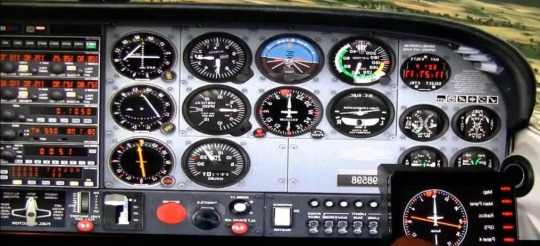
Flight instruments are the tools in the cockpit of an airplane that give the pilot data about the flight circumstance of that airplane. For example, height, velocity, vertical speed, heading and significantly more other vital data. They improve security by permitting the pilot to fly the airplane in level flight and make turns. Without a reference outside the airplane, for example, the skyline. The six basic flight instruments and how those work and how we use them to fly the aircraft. Airspeed indicator:
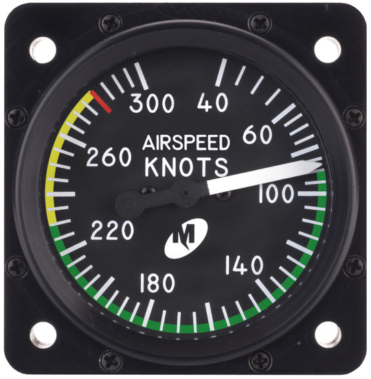
The airspeed indicator is pretty straight forward but the biggest thing that you need to understand is that it reads our airspeed in knots. Well, what is a knot? a knot is simply one nautical mile per hour. Whereas your normal car speedometer just shows you statute miles per hour. The difference between a normal mile versus a nautical mile is that a nautical mile is six thousand and seventy-six feet long instead of the standard 5,280 feet. So one knot is approximately 15% faster than one mile per hour. Now again as the name implies airspeed is simply the speed through the air so for fighting a headwind. Attitude indicator: This is arguably one of the most important flight instruments that we have in the airplane. Especially once we get into instrument flying which is flying in the clouds but even for VFR flying. This is a very important instrument. So the attitude indicator gives us a direct indication of our pitch in our bank. Altimeter:

This is also a very crucial instrument because we need to know how high the roof line. The pilot wants to have the altimeter reading height above sea level. Because the height above the ground is going to vary it means is that ground-level actually varies. For example, the elevation in Chicago is not the same as the elevation in Denver. So the pilot always has its altimeter calibrated to tell the height above sea level. Vertical speed indicator: Vertical speed indicator tells us how fast we are climbing or descending in terms of feet per minute. The needle gives the hundreds of feet per minute. If the needle was set by the 5 that would mean the plane on climbing at 500 feet in a minute. If it was down on the 10 that means the plane descending at a thousand feet per minute below the vertical speed indicator. Heading indicator: Heading indicator just simply tells what direction you flying. The cardinal headings which are north east south and west. With these heading indicators on the numbers, you need to add a zero to the end of it so north is zero degrees or 360.

When the three add a zero to it so that's 30 degrees six is 60 East would be 90 degrees 120 hundred and fifty hundred eighty 210 degrees so on. The thing with the heading indicator is that it doesn't actually know where North is? The heading indicator gives you a much better and easier to use reading of what you’re heading. Tachometer: The tachometer tells us how fast the engine is turning in revolutions per minute, and that's again by hundreds of RPM. The throttle lever is essentially the same as the gas pedal in your car push, it down to go faster in your car push. The lever in the airplane to go faster, so the RPM gauge is how the pilot knows how much power he is using. Vacuum indicator: The vacuum indicator is responsible for running the gyroscopes in the attitude indicator and in the heading indicator. If the vacuum is below the green the pilot may not be getting enough vacuum suction to run the gyros in the attitude in the heading which makes sense. Flight instruments Dealers list in Islamabad: Synchom: SYNCHOM Private limited, they are a Framework Integrator and Arrangements Giving industry and are accomplices of the world driving innovation fabricating organizations. The organization framed by a gathering of experts and specialists. Who have significant information and involvement with the field of Data Innovation, Media transmission., Modern Computerization, Force and Energy. The company gives the best correspondence and security frameworks/items and arrangements according to the client's prerequisites and increases the value of it through brief assistance and backing. Pakistan AeroSpace Council:

The Pakistan Aviation Board (PAeC) is a group association for undertakings dynamic in the aviation, resistance and cutting edge hardware advertise. It is shaped for worldwide advancement of high worth expansion and high innovation players of Pakistan. While meeting the national requirements for innovation obtaining just as fare drove, practical, development of Pakistani Aviation Industries. PAeC underpins the advancement of avionics and related advances. Improves the permeability of the Pakistani aviation comprehensively focusing on a developing piece of the overall industry. It intends to provide food for their individuals' enthusiasm on a political level, encourage organizing between their individuals. Create business openings by sorting out participation to significant business occasions and focus on a well-working triple helix structure. FMG Supplies Pvt Ltd: FMG Worldwide is an aggregate arrangement, works in Pakistan. Universally it bargains in provisioning of Protection Hardware, Extras and Bolster components. It fills in as prime innovation contractual worker and arrangement suppliers for the Outfitted and Non-military personnel Protection powers of Pakistan. The organization spends significant time in uniting part subsystems into an entire framework. And guaranteeing that those subsystems work together consistently. This act of framework combination starts from the plan at their back shops and executed at the field level. Along these lines the frameworks are robotized for immaculate tasks to meet consumer loyalty. Transworld Aerospace:

Transworld Aerospace Pakistan (Pvt.) Ltd. founded in 2012. It aims to develop into the top distributor of fixed-wing and helicopter spare parts. Materials, consumables, chemicals, and repair/modification/overhaul management of rotables. It offers a wide array of services ranging from spare parts. MRO services to managing the entire supply chain through backward integration for the military, airlines, business and corporate operators, general aviation operators and MRO industry. Read the full article
#airplane#AirspeedIndicator#Alimeter#AttitudeIndicator#Dealers#FlightInstruments#HeadingIndicator#Suppliers#VerticalSpeed
0 notes
Text
Flying Qualities Becomes a Science
The stability and controllability of airplanes as they appear to a pilot are called flying or handling qualities. It was many years after airplanes first flew that individual flying qualities were identified and ranked as either desirable or unsatisfactory. Even more time passed before engineers had design methods connected with specific flying qualities. A detailed and fascinating account of the early work in this area of Stanford University Professor Walter G. Vincent’s scholarly book What Engineers Know and How They Know It. We pick up the story in 1919, with the first important step in the process that made a science out of airplane flying qualities.
Vincenti found that the first quantitative stability and control flight tests in the United States occurred in the summer of 1919. MIT Professor Edward P.Warner, working part time at the NACA Langley Laboratory, together with two NACA employees, Frederick H. Norton and Edmund T. Allen, made these tests using Curtiss JN-4H “Jennies” and a de Havilland DH-4. They made the most fundamental of all stability and control measurements: elevator angle and stick force required for equilibrium flight as a function of airspeed.
Warner and Norton made the key finding that the gradient of equilibrium elevator angle with respect to airspeed was in fact an index of static longitudinal stability, the tendency of an airplane to return to equilibrium angle of attack and airspeed when disturbed. The elevator angle–airspeed gradient thus could be correlated with the 1915–1916 MIT wind-tunnel measurements by Dr. Jerome C. Hunsaker of pitching moment versus angle of attack on the Curtiss JN-2, an airplane similar to the JN-4H. In the words of Warner and Norton:
If an airplane which is flying with the control locked at a speed corresponding to the negatively sloped portion of the elevator position curve is struck by a gust which decreases its angle of attack, the angle will continue to decrease without limit. If the speed is low enough to lie on the positively sloping portion of the curve, the airplane will return to its original speed and angle of trim as soon as the effect of the gust has passed.
A strange aspect of the Warner and Norton JN-4H test results was the effect of airspeed on static longitudinal stability. The JN-4H was stable at airspeeds below about 55 miles per hour and unstable above that speed. One would be tempted to look for an aero elastic cause for this, except that wind-tunnel tests of a presumably rigid model showed the same trend. The cause remains a mystery. The 1915–1916 MIT wind-tunnel tests were supplemented in 1918 by the U.S. Air Service at McCook Field with JN-2 wind-tunnel tests, in which the model had an adjustable elevator angle.
The McCook Field group was active in stability and control flight tests at the same period.
As part of an armed service procurement activity, McCook’s primary interest was in airplane suitability for military use, rather than in aeronautical research. Thus, it is understandable that there were no measurements at the level of sophistication of the Norton and Allen tests at the NACA. Captain R. W. Schroeder was one of the Air Service’s top test pilots. His 1918 report on the Packard-Le Pere LUSAC-11 fighter airplane’s handling qualities was completely qualitative.
In the course of the pioneering stability and control flight tests at the NACA Langley Laboratory, instrumentation engineers including Henry J. E. Reid, a future Engineer-in-Charge at Langley, came up with specialized devices that could record airplane motions automatically, freeing pilots from having to jot down data while running stability and control flight tests. Langley Laboratory individual recording instruments developed in the 1920s measure control positions, linear accelerations, airspeed, and angular velocities.
Warner and Norton’s measurements of elevator angles required to trim as a function of airspeed and power for the Curtiss JN4H airplane. They correctly interpreted the data to show static longitudinal instability at airspeeds above the peaks of the curves.
In each recording instrument, a galvanometer-type mirror on a torsion member reflects light onto a photographic film on a drum. A synchronizing device keys together the recordings of individual instruments, putting timing marks on each drum. Frederick Norton said in later years that the work at Langley in which he took the most pride was the development of these specialized flight recording instruments.
The instrument developments put NACA far in front of other groups in the United States who were working on airplane stability and control. The photo recorder was typical technology at other groups running stability and control tests, such as the U.S. Army Air Corps Aircraft Laboratory at Wright Field. In the photo recorder, stability measurement transducers, ordinary flight instruments, and a stopwatch are mounted in a bulky closed box and photographed by a movie camera. Data are then plotted point by point by unfortunate technicians or engineers reading the film.
As another indication of NACA’s advanced flying qualities measurement technology, one of this book’s authors who served in the U.S. Navy during World War II remembers having to borrow a stick force measuring grip from NACA to run an aileron roll test on a North American SNJ trainer.
NACA flying qualities research in the 1920s and early 1930s also trained a group of test pilots, including Melvin N. Gough, William H. McAvoy, Edmund Allen, and Thomas Carroll, in stability and control research techniques, including the ability to reach and hold equilibrium flight conditions with accuracy. As with all good research test pilots, the NACA group worked closely with flight test engineers and in fact took part in discussing NACA’s flying qualities work with outsiders. All of this helped lay the groundwork for the comprehensive flying qualities research that followed.
Edward P. Warner, acting as a consultant to the Douglas Aircraft Company in the design of the DC-4E transport, has the distinction of having first embodied flying qualities research into a specification that could be applied to a new airplane design, much as characteristics such as strength and performance had been specified previously. Warner’s 1935 requirements were based on interviews with airline pilots, industrial and research test pilots, and NACA staff engineers. Warner also recognized the need to put flying qualities requirements on a sounder basis by instrumented flight tests correlated with pilot opinions.
Warner’s ideas were picked up by the NACA and the grand comprehensive attack on airplane flying qualities started. The authorizing document was NACA Research Authorization number 509, “Preliminary Study of Control Requirements for Large Transport Aircraft”. Hartley A. Soule´ a portly, worldly-wise staff member at the NACA Langley Aeronautical Laboratories in Hampton, Virginia, ran tests the following year that attempted to correlate the long-period longitudinal or phugoid mode of motion with pilots’ opinions on handling qualities. The phugoid motion involves large pitch attitude and height changes at essentially constant angles of attack. Eight single-engine airplanes were tested by Soulé and his group. This pioneering attempt showed that neither period nor damping of the phugoid motion had any correlation with pilot opinion.
However, the NACA was fairly launched on the idea of correlating flying qualities measurements with pilots’ opinions. Soulé and his associate, Floyd L. Thompson, outlined the practical steps needed to carry out Warner’s ideas. Flying qualities had to be defined “in terms of factors known to be susceptible of measurement by existing NACA instruments or by instruments that could be readily designed or developed.”
Thompson and Soulé started with what we would now call a set of “straw man” requirements based on Warner’s work, but modified to be measurable by NACA’s instruments. They used a Stinson Reliant SR-8E single-engined high-wing cabin airplane for the tests. It turned out that the only instruments that needed to be specially developed for the Stinson tests were force-measuring control wheel and rudder pedals. These used hydraulic cells developed by the Bendix Corporation as automobile brake pedal force indicators.
The “straw man” NACA requirements seemed to ignore Soulé’s previous findings of the unimportance of the longitudinal phugoid motion, and a reasonably well-damped oscillation of period not less than 40 seconds was specified. Even more curiously, F. W. Lanchester’s research on the phugoid period was quite over looked in the straw man requirements, although Lanchester’s results were given in the well-known 1934 ���Dynamics of the Airplane,” by B. Melvill Jones, which was included in Volume V of W. F. Durand’s Aerodynamic Theory. Lanchester had shown that the phugoid period for all aircraft was linearly proportional to airspeed and would invariably fall below the required 40 seconds at airspeeds under about 150 miles per hour.
Aside from this cavil, Soulé’s research followed reasonable lines. Each straw man requirement was stated, test procedures to check each requirement were spelled out, and the test results were presented and discussed. Some of Soulé’s 1940 test procedures have come down to our day virtually unchanged except for the increased sophistication of data recording. For example, there were measurements of elevator angle and stick force for equilibrium flight at various airspeeds, measurements of time to bank to a specified angle, and, most advanced of all, measurements of the period and damping of the phugoid oscillation as a function of airspeed.
In his published report Soulé’s provides the variations with airspeed for equilibrium flight of both the elevator angle and the control column position from the dashboard. These data would give exactly the same trends were it not for stretch of the control cables that connect the two, under load. Vincenti’s book tells the interesting story of the discovery of the effects of cable stretch on the Stinson data.
Soulé’s report was reviewed in preliminary form by engineers at the Chance Vought Aircraft plant in Connecticut, who noticed that different incidence settings of the horizontal tail affected the variations in elevator angle for equilibrium flight, an unexpected outcome. C. J. McCarthy of Chance Vought wrote to Soulé’s suggesting that the discrepancy might be explained by control cable stretch if the elevator angle had been deduced from the control column position, rather than having been measured directly at the surface itself. According to Vincenti:
Robert R. Gilruth, a young engineer who had recently taken over the flying quality program when Soulé’s moved to wind tunnel duties, measured the stretch under applied load sand found that Chance Vought’s supposition was in fact correct. In tests of later airplanes, elevator angles were measured directly at the elevator. Such matters seem obvious in retrospect, but they have to become known somehow.
Some Stinson measurements called for by the straw man requirements are definitely archaic and not a part of modern flying qualities. Very specific requirements were put on the time needed to change pitch attitude by 5 degrees; these were checked. Likewise, the need to limit adverse yaw in aileron rolls was dealt with by measuring maximum yawing acceleration and comparing it with rolling acceleration. The yaw value was supposed to be less than 20 percent of the roll value. However, all of the pieces were in place now and ready for the next major step.
After the Stinson tests the NACA had the opportunity to test a large airplane, the Martin B-10B bomber. Those results went to the Air Corps in a confidential report of 1938. According to Vincenti, Edward Warner was able to feedback both the Stinson SR-8E and Martin B-10B results to his flying qualities requirements for the Douglas DC-4E, which was just beginning flight tests.
Robert R. Gilruth came to NACA’s Langley Laboratory in 1937 from the University of Minnesota. His slow, direct speech reflected his Midwestern origins. He is remembered for a remarkable ability to penetrate to the heart of problems and to convince and inspire other people to follow his lead. When Gilruth fixed one with a penetrating stare and, with a few nods, explained some point, there was not much argument. Many years later, when NACA became NASA, Gilruth was tapped by the government to head the NASA Manned Spacecraft Center.
Gilruth’s seminal achievement was to rationalize flying qualities by separating airplanes into satisfactory and unsatisfactory categories for some characteristic, such as lateral control power, by pilot opinion. He then identified some numerical parameter that could make the separation. That is, for parameter values above some number, all aircraft were satisfactory, and vice versa. The final step was to develop simplified methods to evaluate this criterion parameter, methods that could be applied in preliminary design.
The great importance of this three-part method is that engineers now could design satisfactory flying qualities into their airplanes on the drawing board. Although proof of good flying qualities still required flight testing, engineers were much less in the dark. The old way of doing business is illustrated by an NACA report on the development of satisfactory flying qualities on the Douglas SBD-1 dive bomber. Discussing a Phase III series of tests in September 1939, the report said, “The best configuration from this phase was submitted to a pilot representative from the Bureau, who considered that insufficient improvements had been made.
Two applications of this new method were published by Gilruth and co-authors Maurice D. White and W. N. Turner to static longitudinal stability and to lateral control power, respectively. White had joined Gilruth at Langley in 1938. Fifteen airplanes ranging in size from the Aeronca K to the Boeing B-15 were tested in the first series, on longitudinal stability. Gilruth and White suggested a design value of 0.5 for the gradient of elevator angle with angle of attack, for the propeller-idling condition, to ensure power-on stability and adequate stick movement in maneuvers.
In the lateral control application of the new method, 28 different wing–aileron combinations were tested, including alterations to the wings and ailerons of two of the airplanes tested. The famous lateral control criterion function pb/2V came into being as a result of this work. Pb/2V is the helix angle described by a wing tip during a full-aileron roll. Gilruth and Turner fixed the minimum satisfactory value of the full-aileron pb/2V as 0.07, expressed in radian measure. A remarkably simple preliminary design estimation technique for pb/2V was presented, based on a single-degree-of-freedom model for aileron rolls.
Robert Gilruth’s early flying qualities work was closed out with publication of “Requirements for Satisfactory Flying Qualities of Airplanes.” This work had appeared in classified form in April 1941. A three-part format was used. First, the requirement was stated. Then there were reasons for the requirement, generally based on flight tests. Finally, there were “Design Considerations” related to the requirement, the all-important methods that would permit engineers to comply with the requirements for ships still on the drawing board.
Gilruth’s 1943 work introduced the concept of the pilot’s stick deflection and force in maneuvers and the criteria of control deflection per g and stick force per g. Vincenti points out that the control deflection and stick force per g criteria may have been independently conceived in Britain by S. B. Gates. Prior to the Gilruth/Gates criteria, stability and control dealt with equilibrium or straight flight conditions. W. H. Phillips calls this quantization of maneuverability one of Gilruth’s most important contributions to airplane flying qualities.
Sidney Barrington Gates had a remarkable career as an airplane stability and control expert in Britain, spanning both World Wars. He left Cambridge University in 1914, in his words, “as an illegitimate member of the Public Schools Battalion of the Royal Fusiliers.” Somebody with unusual perception for those days saw that the young mathematician belonged instead in the Royal Aircraft Factory, the predecessor of the Royal Aircraft Establishment or RAE, and he was transferred there.
Sidney B. Gates, contributor to understanding of airplane spins; originator of neutral and maneuver points, stick force per g, and many other flying qualities matters.
Gates remained at the RAE and as a committee member of the Aeronautical Research Council until his retirement in 1972. His total output of papers came to 130, a large proportion of which dealt with airplane stability and control. His approach to the subject is described by H. H. B. M. Thomas and D. Ku¨chemann in a biographical memoir, as follows:
Gates’s life-long quest – how to carve a way through the inevitably harsh and complex mathematics of airplane motion to the shelter of some elegantly simple design criterion based often on some penetrating simplification of the problem.
This approach is seen at its best in his origination of the airplane static and maneuver margins, simple parameters that predict many aspects of longitudinal behavior. He gave the name “aerodynamic center” to the point on the wing chord, approximately 1/4 chord from the leading edge, where the wing pitching moment is independent of the angle of attack. The wing aerodynamic center concept led to current methods of longitudinal stability analysis, replacing wing center of pressure location.
Gates is also remembered for a long series of studies on airplane spinning, begun with “The Spinning of Aero planes”, co-authored with L. W. Bryant. Gates’ other airplane stability and control contributions over his career cover almost the entire field. They include work in parameter estimation, swept wings, VTOL transition and flying qualities requirements, handling characteristics below minimum drag speed, transonic effects, control surface distortion, control friction, spring tabs, lateral control, landing flap effects, and automatic control.
Together with Morien Morgan, in 1942 Gates made a two-month tour of the United States, “carrying a whole sack load of RAE reports on the handling characteristics of fighters and bombers.” The pair met with the main U.S. aerodynamics researchers and designers at the time, including Hartley Soule´, Gus Crowley, Floyd Thompson, Eastman Jacobs, Robert Gilruth, Hugh Dryden, Courtland Perkins, Walter Diehl, Jack Northrop, Edgar Schmued, W. Bailey Oswald, George Schairer, Kelly Johnson, Theodore von K´arma´n, and Clark Millikan. As Morgan comments, the scope and scale of the 1942 “dash around America” showed what a towering reputation Gates had worldwide.
The U.S. Military Services Follow NACA’s Lead.
Following NACA’s lead, both the U.S. Air Force and the U.S. Navy Bureau of Aeronautics issued flying qualities specifications for their airplanes. Indeed, after the war, the allies discovered that the Germans had established military flying qualities requirements at about the same time. In April 1945 the U.S. Air Force and Navy coordinated their requirements, recognizing that some manufacturers supplied airplanes to both services. The coordinated Air Force specification got the number R-1815-A; the corresponding Navy document was SR-119A. In 1948 the final step was taken and the services put out a joint military flying qualities specification, MIL-F-8785. This document went through many subsequent revisions, the most significant of which was the 1969 MIL-F-8785B.
The main difference between Gilruth’s NACA requirements and the military versions was in the detailed distinctions made by the military among different types of aircraft. For example, in the military version, maneuvering control force, the so-called stick force per g, was generalized to apply to airplanes with any design limit load factor. NACA had recognized only two force levels, for small airplanes with stick controls and for large ones with wheel controls. Special requirements were given in the joint specification for aircraft meant to fly from naval aircraft carriers. MIL-F-8785 and its revisions were incorporated into the procurement specifications of almost all military aircraft after 1948.
The transformation of one particular flying qualities requirement from the original NACA or Gilruth version through successive military specifications can be traced. This requirement is for the longitudinal short-period oscillation. The longitudinal short period is a relatively rapid oscillation of angle of attack and pitch attitude at relatively constant airspeed. The original NACA requirement applies to the stick-free case only, as follows:
When elevator control is deflected and released quickly, the subsequent variation of normal acceleration and elevator angle should have completely disappeared after one cycle.
Gilruth goes on to give reasons for this requirement, as follows:
The requirement specifies the degree of damping required of the short-period oscillation with controls free. A high degree of damping is required because of the short period of the motion. With airplanes having less damping than that specified, the oscillation is excited by gusts, thereby accentuating their effect and producing unsatisfactory rough-air characteristics. The ratio of control friction to air forces is such that damping is generally reduced at high speeds. When the oscillation appears at high speeds as in dives and dive pull-outs, it is, of course, very objectionable because of the accelerations involved.
The first U.S. Air Force specification, C-1815, relaxed the NACA requirement, allowing complete damping in two cycles instead of one. This was done because opinions collected from Air Force pilots and engineers were that the response with the stick fixed was always satisfactory, and so the short-period oscillation was of no importance in design. However, by the time of a 1945 revised specification, R-1815-A, further experience led back to the original NACA requirement of complete damping for the stick-free case in one cycle. A refinement to an analytically more correct form, one better suited for design and flight testing, was made in the next revision, R-1815-B. This is damping to 1/10 amplitude in one cycle, corresponding to a dimensionless damping ratio of 0.367.
Modern design trends, especially higher operating altitudes and wing loadings, decreased the damping in the stick-fixed case, while with irreversible controls the stick-free case essentially disappeared. When the initial stick-fixed damping requirements were set, in MILF-8785, the level was set at a damping ratio of 0.110, or damping to a half-amplitude in one cycle. This relatively low damping requirement is based on NACA experience with research airplanes, whose pilots seem agreeable to low damping levels. As service experience was gained with high-altitude, dense airplanes the trend was reversed and damping requirements were increased again.
This uncertainty in the desirable level of longitudinal short-period damping was typical of what led to ambitious, reasonably well-funded Air Force and Navy research programs to rationalize the flying qualities data base. In the United States, flying qualities flight and ground simulator testing went on all over the country, especially at the NACA laboratories, the Cornell Aeronautical Laboratory, Systems Technology, Inc., NATC Patuxent River, Wright Field, and at Princeton University. British, German, Dutch, and French laboratories also became active in flying qualities research at this time.
Under U.S. Air Force sponsorship, the Cornell Aeronautical Laboratory used a variable-stability jet fighter to make a systematic attack on the longitudinal short-period damping question. Robert P. Harper and Charles R. Chalk ran experiments with variations in short period damping and frequency at constant levels of stick force and displacement per unit normal acceleration. They found a “bull’s-eye” of good damping and natural frequency combinations, surrounded by regions of acceptable to poor performance.
This and similar efforts went into successive revisions of MIL-F-8785, reaching at last the “C” revision of November 1980. All along, the specification writers were guided by peer reviews and conferences involving specification users in the industry. At one point, the U.S. Navy Bureau of Aeronautics requested Systems Technology, Inc. to search for weaknesses in the specification. The resultant report was issued with the attention getting title, “Outsmarting MIL-F-8785.” Good summaries of the revision work may be found in Chalk and Ashkenas.
Civil Airworthiness Requirements.
Military aircraft are procured under comprehensive flying qualities specifications. These specifications are contractual obligations by the manufacturer to a single military customer. On the other hand, the flying qualities of commercial aircraft are generally not governed by contracts with individual customers, but rather by governmental agencies, acting to protect the flying public.
Civil flying qualities requirements are found in airworthiness requirement documents. Compliance with airworthiness standards is proved in flight testing, leading to the award of airworthiness certificates and freedom to market the aircraft. Civil airworthiness requirements are the minimum set that will ensure safety. This is a different objective than military requirements, which not only address safety, but also the effectiveness of military airplanes in their missions. Thus, flying qualities requirements found in civil airworthiness requirements are much less detailed than specified requirements for military airplanes. This is a key distinction between the two sets of requirements.
World-Wide Flying Qualities Specifications.
As mentioned earlier, the German air forces in World War II operated under a set of military flying qualities requirements related to the Gilruth set of 1943. The growth of civil aviation after the war led to a number of national and world-wide efforts to specify flying qualities requirements, in order to rationalize aircraft design and procurement in each country and the international licensing of civil aircraft. The goal of internationally agreed upon civil aircraft flying qualities standards is the responsibility of the International Civil Aviation Organization, an arm of the United Nations. Annex 8 of the ICAO Standards deals with airworthiness, which includes adequate flying qualities.
Standards have also been adopted by individual countries for both civil and military machines. An earlier section traced the evolution of U.S. flying qualities specifications for military aircraft. Similar evolutions took place all over the world. British military specifications are in the UK DEF STAN publications. In particular, DEF-STAN 00-970, issued in 1983, is similar in style to MIL-F-8785C and provides much the same information.
British civil flying qualities requirements were embodied initially in the BCARs, or British Civil Airworthiness Requirements. European standards now apply, as found in the European Joint Aviation Requirements, or JARs, issued by the Joint Aviation Administration. The U.S. versions are the Federal Air Regulations, or FARs, parts 21, 23, 25, and 103 of which deal with airplanes. The wording of the stability and control airworthiness requirements of the FARs is similar to the Gilruth requirements of 1943, which were also concerned with minimum rather than optimum requirements.
Equivalent System Models and Pilot Rating.
The 1980 military flying qualities specification MIL-F-8785C represents the culmination of the representation of airplanes by classical transfer functions, the transfer functions of bare airframes augmented only by simple artificial damping and cross feeds, where needed. In pitch, the bare airframe transfer function of pitching velocity as an output to control surface angle as an input has an inverse second-order denominator and a first-order numerator under the constant airspeed assumption. Three parameters define this function: natural frequency and damping ratio in the denominator and the numerator time constant. The classical bare-airframe transfer function models are called equivalent systems because they can only approximate the transfer functions of complex, augmented flight control systems, such as command augmentation systems and the newer super augmented systems for highly unstable airframes.
The 1980 specification MIL-F-8785C represented another culmination in the development of airplane flying qualities as a science. This is assigning a numerical scale to pilot opinion. In the 1950s A. G. Barnes in the United Kingdom used the initials G, M, and B for good, medium, and bad, with + and − modifiers. The numerical scale, running from 1 to 10, was proposed by George E. Cooper in 1961. The MIL-F-8785C uses the Cooper-Harper rating scale, in which the experience of NASA and Cal span are combined.
A successor to the Cooper-Harper rating scale originated at the College of Aeronautics, Cranfield University to deal better with modern fly-by-wire aircraft. The proposed new scale, called the Cranfield Aircraft Handling Qualities Rating Scale, or CAHQRS, considers separately five parameters – longitudinal, lateral, directional, trim, and speed control – and rates behavior in subtasks according to a Cooper-Harper-type scale, and also a criticality scale. The CAHQRS has been tested initially on a flight simulator. Further experience with this new approach is needed to confirm its expected benefits relative to the Cooper-Harper standard.
The next phase in the unfolding history of the science of flying qualities involves a new level of sophistication, freeing the subject from the constraint of equivalent systems. Mathematical models of the human pilot as a sort of machine are combined with airplane and control system mathematical models and are treated as a combined system. Human physiology and psychology are now enlisted in the study of flying qualities requirements.
The Counterrevolution.
In the late 1980s a counterrevolution of sorts took place, a retreat from authoritative military flying qualities specifications. A new document, called the Military Standard, Flying Qualities of Piloted Vehicles, MIL-STD-1797, merely identifies a format for specified flying qualities. Actual required numbers are filled into blanks through negotiations between the airplane’s designers and the procurement agency. As explained by Charles B. Westbrook, the idea was to let MIL spec users know that “we didn’t have it all nailed down, and that industry must use some judgment in making applications.”
A large handbook accompanies the Military Standard, giving guidance on blank filling and on application of the requirements. The handbook is limited in distribution because its “lessons learned” includes classified combat airplane characteristics. The Military Standard development for flying qualities is associated with Roger H. Hoh of Systems Technology, Inc., and with Westbrook, David J. Moor house, and the late Robert J. Woodcock, of Wright Field.
The demise of the authoritative MIL-F-8785 specification was part of a general trend away from rigid military specifications, with the intent of reducing extraneous and detailed management of industry by the government. Industry designers said in effect, “Get off our backs and let us give you a lighter, better, cheaper product” and “Quit asking for tons of reports demonstrating compliance with arcane requirements.” Some horror stories brought out by the industry people did seem to make the point. The Military Standard is in fact ideal for “skunk works” operations; their managers don’t like more than general directions.
However, the Military Standard seems to bring back the bad old days, the “straw man” requirements of the 1930s, established by pilots and engineers based on hunch and specific examples. It is as if the rational Gilruth method had never been invented. A justification of sorts for the counterrevolution is the tremendous flexibility provided stability and control designers with the new breed of digital flight control systems.
Literally, it is now possible to have an airplane with any sort of flying qualities that one can imagine. Tiny side sticks can replace conventional yoke or stick cockpit controls. Right or left stick or yoke controls no longer have to apply rolling moments to the airplane. Instead, bank angle, constant rolling velocity, or even heading change can now be the result. By casting off the bonds of the rigid MIL-F-8785 specification, a procuring agency can take advantage of radical, innovative control schemes proposed by contractors.
The ability of advanced flight control systems to provide any sort of flying qualities that can be imagined brought a cautionary note from W. H. Phillips, as follows:
The laws of nature have been very favorable to the designers of control systems for old-fashioned subsonic, manually-controlled airplanes. These systems have many desirable features that occur so readily that their importance was not realized until new types of electronic control systems were tried.
Don Berry, a senior engineer at the NASA Dryden Research Center, had similar views:
We have systems capable of providing a wide variety of control responses, but we are not sure what responses or modes are desirable.
A further step in the dismantling of “rational” Gilruth flying qualities specifications is the recent appearance of independent assessment boards, charged with managing the flying qualities levels of individual airplanes. Such a board, called the “Independent Assessment Team,” was formed for the Navy’s new T-45A trainer. Team members for the T-45A included the very senior, experienced engineers William Koven, I. Grant Hedrick, Joseph R. Chambers, and Jack E. Linden.
Procurement Problems.
In either case, whether airplane flying qualities are specified by a standardized specification such as MIL-F-8785 or by negotiations involving a Military Standard, there is still the matter of getting new airplanes to meet flying qualities requirements. In other words, the science of flying qualities is useless unless airplanes are held to the standards developed by that science.
In recent years, new airplanes are being bought by the U.S. armed services in a way that seems designed for poor flying qualities. Program officers are given sums of money sufficient to produce a fixed number of airplanes on a schedule. Military careers rest on meeting costs and schedules. These are customarily optimistic to begin with, having gotten that way in order to sell the program against competing concepts or airplanes.
The combination of military career pressures and optimistic cost and schedule goals usually leads to the dreaded “concurrency” program. Production tooling and some manufacturing proceed concurrently with airplane design and testing, rather than after these have been completed. When flying quality deficiencies crop up late in a concurrent program, requiring modifications to tooling and manufactured parts, it is natural for program officers and their counterparts in industry to resist.
Three notable recent concurrent programs were the Lockheed S-3 Viking anti-submarine airplane, the Northrop B-2 stealth bomber, and the U.S. naval version of the British Aerospace Hawk trainer, being built by McDonnell Douglas/Boeing. The Lockheed S-3 and McDonnell Douglas/Boeing T-45A concurrency stories are involved with the special flying qualities requirements of carrier-based airplanes, on that subject.
Variable-Stability Airplanes Play a Part.
A variable-stability airplane is a research airplane that can be made to have artificially the stability and control characteristics of another airplane. Waldemar O. Breuhaus credits this invention to William M. Kauffman, at the NASA Ames Research Center, about the year 1946. The colorful story that Breuhaus tells is of Kauffman looking out of the window at the Ames flight ramp and seeing three Ryan FR-1 Fireball fighters sitting side by side. Each FR-1 had a different wing dihedral angle. The airplanes had been so modified to try to find in flight testing the minimum amount of effective dihedral angle that pilots would accept. Kauffman said, according to Steve Belsley and some others, “There has to be a better way.”
Ames modified a Grumman F6F-3 Hellcat into the first variable-stability airplane by a mechanism that moved the ailerons in response to measured sideslip angles. An electric servo motor, adapted from a B-29 gun turret drive, moved the F6F’s aileron push–pull rods in parallel to the pilot’s stick input. With this parallel arrangement, the pilot’s stick is carried along when the servo works in response to measured sideslip. This is suitable for automatic pilots, where it is often acceptable and even desired for the pilot’s controls to reflect automatic pilot inputs. However, it does not serve the function of a variable-stability airplane, where the action of the variable-stability mechanism is supposed to be unnoticeable to the pilot.
In the case of the pioneering F6F-3 variable-stability airplane, pilot stick motions were suppressed approximately by an ingenious scheme that canceled the aerodynamic hinge moment corresponding to the commanded aileron deflection. This was done by driving the aileron tab through its own servo motor with a portion of the same signal that was used to drive the aileron push–pull rod.
The F6F-3 variable-stability airplane was followed in the next 30 years by at least 20 other airplanes of the same type. The majority were built by NACA/NASA; the Cornell Aeronautical Laboratories, later Cal span; the German Aerospace Center, or DLR; and the Royal Aircraft Establishment, later DERA. Princeton University, the Canadian National Research Council, Boeing, and research agencies in France and Japan also built them.
The crude compromises of the early machines have given way to ever more sophisticated ways of varying airplane stability and control as seen by the test pilot. Later models, such as the Cal span Total In-Flight Simulator, or TIFS, and the Princeton University Variable Response Research Aircraft, or VRA, have special side-force generating surfaces.
Variable-Stability Airplanes as Trainers
The objectives of most of the variable-stability programs were either to apply the Gilruth method of obtaining flying qualities requirements by exposing pilots to different stability and control levels or to present the flying characteristics of a future machine for evaluation. However, quite by chance, a different use for variable-stability airplanes cropped up. Breuhaus reports that Gifford Bull, the project engineer and safety pilot of a Cal span variable-stability USAFB-26 airplane, was chatting with members of the Navy Test Pilot School at the Patuxent River Naval Air Test Center. The B-26 was at Patuxent to run Navy-sponsored tests on minimum flyable longitudinal handling qualities under emergency conditions. Test Pilot School staffers were struck by what looked like
the unique suitability of the variable stability airplane to serve as a flying class room or laboratory to demonstrate to the school the effects of the myriad flying quality conditions that could be easily and rapidly set up.
A trial run in 1960 was such an instant success that the program was broadened to include the Air Force Test Pilot School at Edwards Air Force Base, and a second B-26 was added. The aging B-26s were eventually replaced by two variable-stability Learjet Model 24s. By the end of 1989 nearly 4,000 service, industrial, and FAA pilots and engineers had instruction or demonstrations using the variable-stability B-26s and Learjet’s.
In a more recent application of an airplane modified to fly like another airplane for training, NASA used a Grumman Gulfstream G-2 in a high drag configuration to train pilots to fly the Space Shuttle’s steep, fast-landing approach profile, starting at an altitude of about 30,000 feet.
The Future of Variable-Stability Airplanes.
The engineers at NASA, Cal span, DERA, the Canadian NRC, Princeton University, and other European and Asian laboratories who had so much to do with the development of variable-stability airplanes can point to impressive accomplishments using these devices. Variable-stability airplanes shed light on many critical issues, such as the role of roll-to-yaw ratios on required Dutch roll damping, permissible levels of spiral divergence, and the effect of longitudinal flying qualities on instrument landing system landing approaches. Variable-stability airplanes have also provided a preliminary look at the flying qualities of radical new airplanes such as the Convair B-58 Hustler; the Rockwell X-15, XB-70, B-1, and Space Shuttle Orbiter; the Lockheed A-12 and F-117A; the Grumman X-29A; various lifting body projects; and the Anglo-French Concorde before those new airplanes flew.
The TIFS machine, based on a reengined Convair C-131 Btransport, has had a particularly productive career. Cal span engineers provided the TIFS with the ability to add aerodynamic forces and moments to all 6 degrees of freedom. Flight tests are carried out from an evaluation cockpit built into the airplane’s nose, while a safety crew controls the airplane from the normal cockpit. Some 30 research programs have been run on this airplane. The majority of them were general flying qualities research; ten programs were on specific airplanes. A T-33 variable-stability airplane also had a very productive career, with more than 8,000 flying hours to date. A new application of variable-stability airplanes has been reported from the DLR, in which the ATTAS in-flight simulator investigated manual flight control laws for a future 110-seat Airbus transport airplane.
In spite of this impressive record, there are reasons to look for limitations in the future use of variable-stability airplanes in the engineering development of new aircraft. A significant obstacle is the practical difficulty in updating and maintaining the vast computer data bases needed to represent the mathematical models of complex digital flight control and display systems and nonlinear, multivariable aerodynamic data bases. Maintaining current data bases should be inherently easier for locally controlled ground-based simulators, as compared with variable-stability airplanes operated by another agency at a remote site.
Another limitation to the future use of variable-stability airplanes in the engineering development of specific air planes has to do with the cockpit environment. Correctly detailed controls, displays, and window arrangements, important for a faithful stability and control simulation, may be difficult to provide on a general-purpose variable-stability airplane. Correct matching of accelerations felt by the pilot is also desirable. Although variable-stability airplanes do provide the pilot with both acceleration and visual cues, both cannot be represented exactly, along with airplane motions, unless the variable-stability machine flies at the same velocity as the airplane being simulated and unless the pilot is at the same distance from the airplane’s center of gravity in both cases.
Those conditions are rarely satisfied, except in some landing approach simulations. For example, the Princeton University VRA, flying at 105 knots, has been used to simulate the Space Shuttle Orbiter flying at a Mach number of 1.5. Pilot acceleration cues can be retained under a velocity mismatch of this kind by a transformation of variable-stability airplane outputs that amounts to using a much higher yaw rate. Likewise, pilot location mismatch is conveniently corrected for by a transformation on the sideslip angle. If these transformations are applied to correct pilot acceleration cues, visual cues will be made incorrect. An alternative scheme to provide correct pilot acceleration cues relies on the direct side and normal force capabilities of advanced machines such as the TIFS.
In general, the cockpit environment of a new airplane can be represented fairly readily in a ground-based simulator. Correct visual cues can be provided as well, although there are often troubling lags in projection systems. The major loss in fidelity for ground simulators, as compared with variable-stability airplanes, comes from the compromises or actual losses in pilot motion cues. When these are provided by servo-driven cabs, accelerations must be washed out. That is, to avoid unreasonably large simulator cockpit cab motions, only acceleration on sets can be represented. Sustained accelerations must be tapered off smoothly and quickly in the ground-based systems, or they must be simulated by pressures applied to the pilot’s bodies with servo-controlled pressure suits. Belsley provided an early summary paper in this area. Later on, Ashkenas and Barnes reviewed the utility and fidelity of ground-based simulators in flying qualities work.
There is a debatable size problem involved with the use of variable-stability airplanes. W. H. Phillips points out that in Robert Gilruth’s original handling qualities studies, contrary to the expectations of many people, pilots were satisfied with much lower values of maximum rolling velocity on large airplanes than on small ones. This finding is reflected in the pb/2V criterion of acceptability, which allows half as much maximum rolling velocity when the wing span is doubled at the same airspeed.
Again, pilots of small airplanes choose lower control forces than do pilots of large airplanes. Phillips concludes that pilots adapt to airplanes of different sizes and that erroneous results may be obtained if this adaptable characteristic of the human pilot is not accounted for. This might be the case when a large airplane is simulated with a much smaller variable-stability airplane, or vice versa.
A counterargument is that two fundamental airplane dynamics properties affecting airplane feel vary systematically with airplane size, giving the pilot a cue to the size of the airplane, even if all that the pilot sees of the airplane is the cockpit and the forward view out of the windshield. Short-period pitch natural frequency shows a systematic trend downward with increasing airplane weight and size. The roll time constant, the time required for an airplane to attain final rolling velocity after step aileron inputs, shows a systematic trend upward with increasing airplane size.
Thus, a small variable-stability airplane whose dynamics match those of a large airplane may well feel like the large one to the pilot. W. O. Breuhaus reports that this seems to be the case:
the pilot must be able to convince himself that he is flying the assigned mission in the airplane being simulated...one of the variable-stability B-26’s was used to simulate the roll characteristics of the much larger C-5A before the latter airplane was built. The results of those tests showed a less stringent roll requirement for the C-5A than was being specified for the airplane, and these results were verified when the C-5A flew.
The relative merits of variable-stability air planes as compared with ground-based simulators for representing airplane flying qualities are still being debated; each has its proponents. However, it is a fact that sophisticated ground-based simulators are now absolutely integral to the development of new aircraft types, such as the Northrop B-2 and the Boeing 777. Typically, ground-based simulators handy to the engineering staff are in constant use during airplane design development. At the same time, variable-stability airplanes remain important tools for design validation and for the development of generalized flying qualities requirements.
The question of when variable-stability airplane simulation is really necessary is taken up by Gawron and Reynolds. They provide a table of ten flight conditions that seem to require in-flight simulation, together with evidence for each condition. An example condition is a high gain task. Evidence for this is the space shuttle approach and landing and other instances such as YF-16 and YF-17 landings.
The Air Force operates the new VISTA/F-16D variable-stability airplane and the Europeans are running impressive programs of their own. However, in-flight simulation was not considered for the Jaguar fly-by-wire, the EAP, or for the Eurofighter. Shafer provides a history of variable-stability airplane operations at the NASA Dryden Flight Research Center, with an extensive bibliography.
The V/STOL Case.
Vertical or short takeoff and landing airplane flying qualities requirements present special problems because V/STOL airplane technology covers a large range of possibilities. So far, we have seen tilt rotor, lift fan, vectored thrust, blown flaps, and convertible rotor wing versions. Although the military services have taken up the challenge and in 1970 issued a V/STOL flying qualities specification, MIL-F-83300, there is a danger that the requirements are specific to individual designs, those available for testing at the time.
MIL-F-83300 recognizes three airspeed regimes, from hover to 35 knots, from 35 knots to an airspeed where conventional flying qualities requirements apply, and airspeeds above conventional flying speeds. Requirements are either for small perturbations about some fixed operating point or for accelerated or transitional flight. The V/STOL small-perturbation longitudinal dynamics requirements take the familiar MIL-8785 form of acceptable and unsatisfactory boundaries in terms of real and imaginary parts of the system roots. So do the lateral-directional requirements resemble those for conventional airplanes, as requirements on the shape of the bank angle versus time curve for rolls and on permitted adverse yaw.
The Air Force Wright Laboratory’s VISTA, or multiaxis thrust-vectoring airplane, a variable-stability machine based on the General Dynamics F-16D. Thrust is vectored up to 17 degrees in pitch and yaw, primarily for high-angle-of-attack research.
A complication when applying the familiar period and damping requirements to the roots of V/STOL motions is convergence of the ordinary modes of motion at very low airspeeds. For a powered-lift STOL configuration the longitudinal short-period and phugoid modes merge at an equilibrium weight coefficient, equivalent to the lift coefficient, of 3.5. A similar trend shows up in the lateral case, where a spiral mode approaches in time constant the usually much shorter rolling mode at a large value of the equilibrium weight coefficient.
The problem of establishing V/STOL flying qualities requirements that are not tied to specific configurations was taken up again after MIL-F-83300, for the most part with the help of ground simulations and variable-stability airplanes. In 1973, Samuel J. Craig and Robert K. Heffley used analysis and ground simulation to explore the role of thrust vector inclination during STOL landing approaches.
Still later, in papers delivered in 1982 and 1983, Roger H. Hoh, David G. Mitchell, and M. B. Tischler looked for flying qualities generalizations in VTOL transitions and STOL path control for landings. Precise pitch attitude control at high bandwidth appears to be critical in transitions because of the sensitivity of vertical rate to pitch attitude. However, the writers found a number of possible requirements for the landing flare control maneuver of STOL airplanes. That series closed out with a major effort to extend the MIL Prime Standard and Handbook concept to STOL Landings.
An area that seems to require more attention is the lift loss in the vortex ring state during increases in descent rate. Vortex rings recirculate the rotor down flow back into the rotor, instead allowing it to descend and produce lift. This is a performance problem for single-rotor helicopters. However, for the tilt-rotor V-22 Osprey, a vortex ring on one of two laterally located rotors is believed to have produced an unrecoverable roll.
The considerable experience gained by DERA and BAE systems in V/STOL projects, leading to the Harrier and the VAAC Harrier, is summarized by Shanks and Fielding. One key finding was that eliminating conscious mode changing provides a large reduction in pilot work load. The V/STOL becomes a “conventional aircraft that can hover.” Another finding was the need to use closed-loop analysis to specify propulsion system characteristics in terms of bandwidth and response linearity.
Pilot-in-the-loop technology has made significant contributions to understanding the special flying qualities requirements of STOL and VTOL airplanes. This approach is especially valuable because it is not closely tied to the design details of specific machines.
Two Famous Airplanes.
NACA measured the flying qualities of the super marine Spitfire VA fighter in 1942 and the Douglas DC-3 transport in 1953, both at the Langley Laboratory. These airplanes had been built in large numbers, had served magnificently in World War II, and had inspired great affection among their pilots. Yet neither of these famous airplanes had the specified level of the most basic stability of them all, static longitudinal stability, as measured by the elevator angles required for steady flight at various airspeeds. This form of stability is often called stick-fixed stability.
The Spitfire shows neutral stick-fixed stability under all flight conditions. The DC-3 is stable only in power-off glides or with cruise power. With normal rated power or in a power approach condition at aft loadings, increasing amounts of down elevator are needed as the air speed is reduced, along with push column forces. For both air planes there are other less striking deviations from NACA and military stability and control specifications. What should be made from all of this?
The Spitfire and DC-3 cases should not furnish an excuse to dismiss flying qualities requirements. It is reasonable to assume that if the Spitfire and DC-3 were longitudinally stable under all flight conditions, both of these fine airplanes would have been even better. In fact, the Spitfire Mark 22, developed at the end of the war, had a 27 percent increase in tail areas and flew “magnificently,” according to one account. The bottom line is that nobody has ever found it feasible to run definitive, statistically valid experiments on the value of good flying qualities in terms of reducing losses in accidents or success in military missions. Instead, we rely on common sense. That is, it is highly plausible that good handling qualities in landing approach conditions will reduce training and operational accidents and that precise, light, effective controls will improve air-to-air combat effectiveness. That plausibility is essentially what energizes the drive for good flying qualities, in spite of apparent inconsistencies, such as for the Spitfire and DC-3.
Changing Military Missions and Flying Qualities Requirements.
Flying qualities requirements for general aviation and civil transport airplanes are predictable in that these airplanes are almost always used as envisioned by their designers. This is not so for military airplanes. The record is full of cases in which unanticipated uses or missions changed flying qualities requirements. Four examples follow.
A4D-1 Skyhawk. The A4D-1, later the A-4, was designed around one large atomic bomb, which was to be carried on the centerline. A really small airplane, the A4D-1 sits high on its landing gear to make room for its A-bomb. The airplane was designed to be carrier-based. However, the A4D-1 was used instead mainly as a U.S. Marine close-support airplane, carrying conventional weapons and operating from single-runway airstrips, often in crosswinds. The vestigial high landing gear meant that crosswinds created large rolling moments about the point of contact of the downwind main tire and the ground. In simpler terms, side winds tried to roll the airplane over while it was landing or taking off. Originally, pilots reported that it was impossible to hold the upwind wing down in crosswinds, even with full ailerons. Upper surface wing spoilers had to be added to the airplane to augment aileron control on the ground.
B-47 Stratojet. This airplane started life as a high-altitude horizontal bomber. It’s very flexible wings were adequate for that mission, but not for its later low-altitude penetration and loft bombing missions. Loft bombing requires pull-ups and rolls at high speed and low altitude. In aileron reversal ailerons act as tabs, applying torsional moments to twist a wing in the direction to produce rolling moments that overpower the rolling moments of the aileron itself. This phenomenon limited the B-47’s allowable airspeed at low altitudes.
F-4 Phantom. The F-4 was developed originally for the U.S. Navy as a long-range attack airplane, then as a missile-carrying interceptor. A second crew member was added for the latter role, to serve as a radar operator. Good high angle of attack stability and control were not required for these missions, but then the U.S. Air Force pressed the F-4 into service in Vietnam as an air superiority fighter. Belatedly, leading-edge slats were added for better high angle of attack stability and control.
NC-130B Hercules. This was a prototype C-130 STOL version, fitted with boundary layer control. The airplane’s external wing tanks were replaced by Allison YJ56-A-6 turbojets to supply bleed air for the boundary layer control system. At the reduced operating air speeds made possible by boundary layer control the C-130’s un-augmented lateral-directional dynamics, or Dutch roll oscillations, were degraded to unacceptable levels.
“Systems engineering” as a discipline was a popular catchphrase in the 1950s. Airplanes and all their accessories and logistics were to be developed to work together as integrated systems, for very specific missions. The well-known designer of naval airplanes Edward H. Heinemann was not impressed. Heinemann’s rebuttal to systems engineering was, “If I build a good air plane, the Navy will find a use for it.” Heinemann’s reaction to systems engineering seems justified by the four cases cited above, in which flying qualities requirements for the airplanes changed well after the designs had been fixed.
Long-Lived Stability and Control Myths.
The achievements of S. B. Gates, R. R. Gilruth, and others in putting airplane stability and control on a scientific basis have not eliminated a number of early myths attached to the subject. Dr. John C. Gibson lists no fewer than 15 of these myths and counters them with what we know to be correct. A few of the Gibson’s list of 15 myths and corrections follow:
Wing center of pressure (cp) movement affects longitudinal stability. Correction: Wing center of pressure movement with angle of attack is controlled by the wing’s zero-lift pitching moment coefficient about its aerodynamic center. This parameter affects only trim for rigid air planes. Wing center of pressure has been discarded in modern stability and control calculations and replaced by wing aerodynamic center and zero-lift pitching moment coefficient.
A down tail load is required for stability. Correction: Stability is provided by the change in tail load with change in airplane angle of attack. The change is independent of the direction of the initial load.
Gibson comments that this myth survives in FAA private pilot examinations and in an exhibit at the National Air and Space Museum in Washington. This subject is distinct from the instability caused by tail down load in the presence of propeller slipstream.
A stable airplane is less maneuverable than an unstable one. Correction: Unstable airplanes are notoriously difficult to control precisely. Given light control forces, a stable airplane can be pitched rapidly to a precise load factor or aiming point. Gibson says, “...the Hurricane, Typhoon, and Tempest were highly maneuverable and were greatly superior as gun platforms to the skittish Spitfire.”
0 notes
Text
longish excerpt of John Barth’s “On with the Story”
She (I mean our distraught “Freeze Frame protagonist) happens to be gridlocked in actual sight of that river: There’s the symbolic catenary arch of the “Gateway to the West,” and beyond it are the sightseeing boats along the parkfront and out among the freight-barge strings. As She tries to divert and calm herself by regarding the nearest of those tourist boats — an ornate replica of a Mark Twain-vintage sternwheeler, just leaving its pier to nose upstream — her attention is caught by an odd phenomenon that, come to think of it, has fascinated her since small-girlhood (happier days!) whenever she has happened to see it: The river is, as ever, flowing south, New Orleansward; the paddle-steamer is headed north, gaining slow upstream momentum (standard procedure for sightseeing boats, in order to abbreviate the anticlimactic return leg of their tour), and as it begins to make headway, a deckhand ambles aft in process of casting off the vessel’s docklines, with the effect that he appears to be walking in place, with respect to the shore and Her angle of view, while the boat moves under him. It is the same disconcerting illusion, She guess, as that sometimes experienced when two trains stand side by side in the station and a passenger on one thinks momentarily that the other has begun to move, when in fact the movement is his own — an illusion compoundable if the observer on Train A (this has happened to Her at least once) happens to be strolling down the car’s aisle like that crewman on the sternwheeler’s deck, at approximately equal speed in the opposite direction as the train pulls out. Dear-present-reader Alice suddenly remembers one such occasion, somewhere or other, when for a giddy moment it appeared to her that she herself, aisle-walking was standing still, while Train A, Train B, and Boston’s South Street Station platform (it now comes back to her) all seemed in various motion.
As in fact they were, the “Freeze Frame” narrator declares in italics at this point, his end-of-paragraph language having echoed mine above, or vice verse — and here the narrative, after a space-break, takes a curious turn. Instead of proceeding with the story of Her several concentric plights — how She extricates or fails to extricate herself from the traffic jam; whether She misses the interview appointment or, making it despite all, nevertheless fails to get the university job; whether or not in either case She and the twins slip even farther down the middle-class scale (right now, alarmingly, if Bill really “cuts her odd” as threatened, She’s literally about two months away from the public-assistance rolls, unless her aging parents bail her out: she who once seriously considered Ph.D.hood and professorship); and whether in either of those cases anything really satisfying, not to say fulfilling, lies ahead for her in the second half of her life, comparable to the early joys of her marriage and motherhood — instead of going on with these nested stories, in which our Alice understandably takes a more than literary interest, the author here suspends the action and launches into an elaborate digression upon, of all things, the physics of relative motion in the universe as currently understood, together with the spatiotemporal nature of written narrative and — Ready? — Zeno’s Seventh Paradox, which three phenomena he attempts to interconnect more or less as follows: Seat-belted in her gridlocked and overheating Subaru, the protagonist of “Freeze Frame” is moving from St. Louis’s Gateway Arch toward University City at a velocity, alas, of zero miles per hour. Likewise (although her nerves are twinging, her hazel eyes brimming, her pulse and respiration pulsing and respiring, and her thoughts returning already from tourist boats to the life-problems that have her by the throat) her movement from the recentest even in her troubled story to whatever next: zero narrative mph, so to speak, as the station wagon idles and the author digresses. Even as the clock of Her life is running, however, so are time in general and the physical universe. The city of St. Louis and its temporarily stalled downtown traffic, together with our now-sobbing protagonist, the state of Missouri, and variously troubled America, all spin eastward on Earth’s axis at roughly a thousand miles per hour. The rotating planet itself careens through its solar orbit at a dizzying 66,662 miles per hour (with the incidental effect that even “stationary” objects on its surface, like Her Subaru, for half of every daily rotation are “strolling aft” with respect to orbital direction, though at nothing approaching orbital velocity). Our entire whirling system, meanwhile, is rushing in its own orbit through our Milky Way Galaxy at the stupendous rate of nearly half a million miles per hour: lots of compounded South Street Station effects going on within that overall motion! What’s more, although our galaxy appears to have no relative motion within its Local Group of celestial companions, that whole Local group — plus the great Virgo Cluster of which it’s a member, plus other, neighboring multigalactic clusters — is apparently rushing en bloc at a staggering near-million miles per hour (950,724) toward some point in interclusteral space known as the Great Attractor. And moreover yet — who’s to say finally? — that Attractor and everything thereto so ardently attracted would seem to be speeding at an only slightly less staggering 805,319 mph toward another supercluster, as yet ill-mapped, called the Shapley Concentration, or, to put it mildly, the Even Greater Attractor. All these several motions-within-motions, mind, over and above the grand general expansion of the universe, wherein even as the present reader reads this present sentence, the galaxies all flee on another’s company at speeds proportional to their respective distances (specifically, in scientific metrics, at the rate of fifty to eighty kilometers per second — let’s say 150,000 miles per hour — per “megaparsec” from the observer, a megaparsec being one thousand parsecs and each parsec 3.26 light-years). Don’t think about this last too closely, advises the author of “Freeze Frame,” but in fact out Alice — who has always had a head for figures, and who once upon a time maintained a lively curiosity about such impersonal matters as the constellations, at least, if not the overall structure of the universe — is at this point stopped quite as still by vertiginous reflection as is the unnamed Mrs. William Alfred Barns by traffic down there in her gridlocked Subaru, and this for several reasons. Apart from the similarities between Her situation vis-à-vis “Bill” and Alice’s vis-à-vis Howard — unsettling, but not extraordinary in a time and place where half of all marriages end in separation or divorce — is the coincidence of Alice’s happening upon “Freeze Frame” during a caesura in her own life-story and reading through the narratives of Her nonplusment up to the author’s digression-in-progress just as, lap-belted in a DC-10 at thirty-two thousand feet, she’s crossing the Mississippi River in virtual sight of St. Louis not long past midday (Central Daylight Savings Time), flying westward at an airspeed of six hundred eight miles per hour (so the captain has announced), against a contrary prevailing jet stream of maybe a hundred mph, for a net speed-over-ground of let’s say five hundred, while Earth and its atmosphere spin eastward under her, carrying the DC-10 backward (though not relatively) at maybe double its forward airspeed, while simultaneously the planet, the solar system, the galaxy, and so forth all tear along in their various directions at their various clips — and just now two flight attendants emerge from the forward galley and stroll aft down the parallel aisles like that deckhand on the tourist stern-wheeler, taking the passengers’ drink orders before the meal service. Alice stares awhile, transfixed, almost literally dizzied, remembering from her happier schooldays (and from trying to explain relative motion to Sam and Jessica one evening as the family camped out under the stars) that any point or object in the universe can be considered to be at rest, the unmoving center of it all, while everything else is in complex motion with respect to it. The arrow, released, may be said to stand still while the earth rushes under, the target toward, the archer away from it, et cetera.
[. . .]
Back, rather, she goes, to that extended digression, wherein by one more coincidence (she having just imaged the arrow in “stationary” flight — but not impossibly she glanced ahead in “Freeze Frame” before those flight attendants caught her eye) the author now invokes two other arrows: the celebrated Arrow of Time, along whose irreversible trajectory the universe has expanded ever since Big Bang, generating and carrying with it not only all those internal relative celestial motions but also the story of Mr. and Mrs. W. A. Barnes from wedlock through deadlock to gridlock (and of Alice and Howard likewise, up to her reading of these sentences); and the arrow in Zeno’s Seventh Paradox, which Alice may long ago have heard of but can’t recollect until the author now reminds her. If an arrow in flight can be said to traverse every point in its path from bow to target, Zeno teases, and if at any given moment it can be said to be at and only at some on of those points, then it must be at rest for the moment it’s there (otherwise it’s not “there”); therefore it’s at rest at every moment of its flight, and its apparent motion is illusory. To the author’s way of thinking, Zeno’s Seventh Paradox oddly anticipates not only motion pictures (whose motion truly is illusory in a different sense, our brain’s reconstruction of the serial “freeze-frames” on the film) but also Werner Heisenberg’s celebrated Uncertainty Principle, which maintains in effect that the more we know about a particle’s position, the less we know about its momentum, and vice versa — although how that principle relates to Mrs. Barne’s sore predicament, Alice herself is uncertain. In her own mind, the paradox recalls that arrow “at rest” in mid-flight aforeposited as the center of the exploding universe . . . like Her herself down there at this moment of Her story; like Alice herself at this moment of hers, reading about Hers and from time to time pausing to reflect as she reads; like very one of us — fired from the bow of our mother’s loins and arcing toward the target of our grave — at any and every moment of our interim life-stories.
[. . .]
[. . .]then returns, glass in hand, to the freeze-framed “Freeze Frame,” whose point she think she’s beginning to see, out of practice though she is in reading “serious” fiction. To the extent that anything is where it is [the author therein now declares], it has no momentum. To the extent that it moves, it isn’t “where it is.” Likewise made-up characters in made-up stories; likewise ourselves in the more-or-less made-up stories of our lives. All freeze-frames [he concludes (concludes this elaborate digression, that is, with another space-break, after which the text, perhaps even the story, resumes)] are blurred at the edges.
An arresting passage, Alice acknowledges to herself.
0 notes
Text
TQK3
Nicknames, cool fonts, symbols and tags for TQK. Create good names for games, profiles, brands or social networks. Submit your funny nicknames and cool ... EASTERN AUSTRALIA AIRLINES PTY. LIMITED C Wing Level 1 10 Bourke Road MASCOT NSW 2020 Australia. Registered operator commencement date:. Buy MX Elements Offset Quadrant Shower Tray with Waste 1200mm x 900mm Left Handed today. MX Part No: TQK. Free UK delivery in approx 3 working days. 3 TqK <3 Introduces the new Vindictive Outfit! (Shoes not included) This sleek two piece outfit comes with a 6 texture HUD for both top and bottom... All Details For VH-TQK (Euro-Asia Air DHC-8 315) - Flightera.net. KTQK (TQK), Scott City Mun: airport and runway data, TAF, METAR, Detailed and original NOTAMs. How Do You Spell TQK? Correct spelling for the English word "TQK" is
Airport Identifier: TQK. Airport Status: Operational. Longitude/Latitude: 100-53-04.0000W/38-28-30.1000N -100.884444/38.475028 (Estimated). Elevation: 2968 ... TQK, a song by Midget Fan Club on Spotify. ... TQK. By Midget Fan Club. 2002 ��� 1 song, 5:06. Play on Spotify. 1. TQK. 5:060:30. Featured on A Total Nightmare ... Shows the flight distance and flight time between Scott City Municipal Airport (TQK) and San Diego International Airport (SAN) and displays it on an interactive ... Abbreviation tqk. Found 1 abbreviations in 1 groups ... Abbreviations similar to tqk. Tach - Tachometer; TAS - True airspeed; TAWS - Terrain awareness warning ...
Stock analysis for Wendy's Co/The (TQK:BX Worldcaps) including stock price, stock chart, company news, key statistics, fundamentals and company profile. Tqk kitchens Kitchen Renovations & Designs - Prestons, New South Wales, 2170, Business Owners - Is Tqk kitchens in Prestons, NSW your business? You Yourself descend to propagate the transcendental science of devotional service unto the hearts of the advanced transcendentalists and mental speculators, ... Latest Wendys Co (TQK:STU) share price with interactive charts, historical prices, comparative analysis, forecasts, business profile and more.
0 notes