#2n7000
Text

Headphone Amplifier DIY
全段差動プッシュプル・ヘッドホンアンプ
Output Transformer : SD-45
#2sk170#2n7000#sd-45#shioya musen#シオヤ無線#diy audio#headphone amplifier#all stage differential amplifier#全段差動#st-45
0 notes
Text
DIY Dumble-like sounding MOSFET Overdrive

The Hermida Zendrive guitar pedal we will study, assemble and listen to today is a true masterpiece. Many say its sound is close to the Holy Grail of guitar amplification - Dumble Overdrive Special.
Other people are more pessimistic in their judgments. Still, the precise response to the picking dynamics, the Voicing tuning options, and the sheer beauty of this overdrive's sound are simply impossible not to love.
But before we study the Lovepedal Zendrive or its copy of the Landtone Phoenix song, or the Aion effects Azimuth dynamic overdrive, we'll study the evolution of the MOSFET overdrives that finally resulted in the development of this gem.
Fulltone OCD

Mike Fuller was one of the first to start using MOSFETs instead of diodes to limit the amplified guitar signal in 2004.
His Obsessive-Compulsive Drive overdrive-distortion pedal is built on a standard circuit with one dual op amp. The first operational amplifier, X1, amplifies the amplitude of the guitar signal by a factor from 8 to 463 times, depending on the position of the drive control X3. This is a 1-megohm potentiometer.

Further, through resistor R9, the signal is fed to the limiter, which comprises 2N7000 MOSFETs M1 and M2 connected in parallel. A germanium diode D1 - 1N34A is additionally included in series with M2, which makes the limiter asymmetrical and, therefore, makes more interesting sound.
A limiter in overdrives is usually included in the negative feedback circuit of an operational amplifier (i.e., in parallel with C6). Such a limiter is called a soft limiter.
And here, a hard limitation is applied: clipping sections are included between the preamplifier output of the gain section and the virtual ground - half of the supply voltage Vref, formed by resistors R4 and R7.
Virtual ground is used in the unipolar powering of operational amplifiers to amplify analog signals, such as audio signals. The guitar signal does not change from zero to plus but from minus to plus, passing through zero.
To prevent the signal from being limited to the circuit's ground, it is shifted in the plus direction by half the supply voltage.
Such hard limiting is typical for distortion pedals. But by using MOSFETs instead of diodes or LEDs, the top of the signal is not cut hard but softly rounded. Therefore, OCD can work as both distortion and overdrive.
Due to the smoothed peaks of the limited signal, the sound is highly dependent on the sound's attack dynamics. For rock and especially blues, this is very valuable. With modern metal pickups that compress the dynamic range of the signal, it can help make solos sounding more sweet.
The second operational amplifier X3 amplifies the limited signal by a factor of 3.8, correcting its timbre. Capacitors C6 and C9 prevent the self-excitation of operational amplifiers at high frequencies.
Next is a simple passive tone knob, which implies a treble leak circuit. Potentiometer X4 10 kilohms and capacitor C11 47 nanofarads are connected in the same way as on the pickguard of any electric guitar.
The Switch1 switch changes the circuit's output impedance as if the high-impedance and low-impedance pickups were switched. When it's open, you get a transparent overdrive like the Klon Centaur, and when it's closed, you can get a more aggressive sound like the Marshall Plexi.
Hermida Audio Zendrive

The Zendrive pedal's authors, Hermida audio technology (now produced by LOVEPEDAL LLC), have undoubtedly studied the Fulltone OCD thoroughly. Let's find the differences between the two circuits.
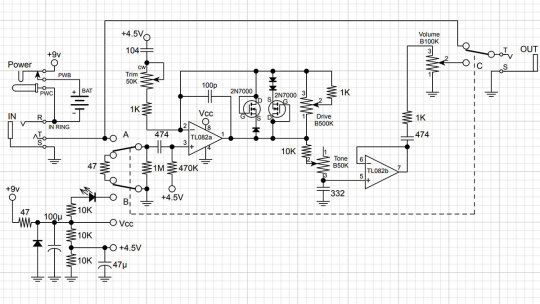
First, the limiter is included in the operational amplifier feedback, that is, between the output and the inverting input, not between the output and virtual ground. That is, here we have a soft limiter.
Secondly, one diode is added in series with each MOSFET. Clipping remains asymmetric: we have one diode in the left arm of the limiter and two diodes in the right arm.
Third, the second operational amplifier is used as a voltage repeater, aka buffer: the output is directly connected to the inverting input.
Fourth, the tone control is implemented a little differently: two OCD`s switchable resistors are replaced by a potentiometer.
And finally, the most critical, fifth difference. A potentiometer is included in the tone correction circuit between the inverting input of the first operational amplifier and the artificial midpoint.
This fourth knob, Voicing, or Character, allows you to smoothly adjust the lower frequencies in the overdrive structure over a wide range, similar to the Resonance control on many tube guitar amps.
The potentiometer is signed as a trimmer in the diagram because some pedal makers don't want to install a fourth knob on the pedal`s body. This is what Landtone did when developing the Phoenix Song Overdrive DIY kit.
The developer suggests installing the trimmer on the PCB, and to access it, you need to disassemble the pedal by unscrewing the footswitch nut and taking out the PCB.
But I will not be lazy to drill an extra hole in the pedal body and install a potentiometer with a knob, connected to PCB by wires instead of the trimmer. Because I consider this regulator simply invaluable and irreplaceable.
Before we get to assembly and testing, let's look at another pedal with a similar adjustment. However, it is based not on the Fulltone OCD but on the Ibanez Tube Screamer.
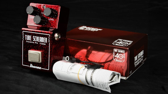
The Precision Drive

This is a signature pedal by Misha Mansour of Periphery, manufactured by Horizon Devices. Compared to the original Overdrive Pro TS808, the circuit adds a noise suppressor, which we will not consider, and an exciting ATTACK switch.
The Precision Drive scheme was studied and partially replicated by PedalPCB and PCB Guitar Mania. They are manufacturers of DIY kits for guitarists. Their products are called Dwarven Hammer and Collision Drive, respectively. A noise gate is not provided there, but the attack switch is implemented. This is the main difference between Precision Drive and many other overdrive pedals.
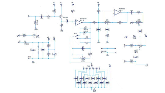
In the Fulltone OCD schematic, we saw a resistor switch at the tone shaping circuit in the output section. The Zendrive has a variable resistor in the preamp's RC circuit which is controlling the overdrive structure.
Precision Drive has a constant resistor in the same place, between the inverting input of the overdrive section operational amplifier and the virtual ground, but the capacitors are switched.
This is the same thing: we change the time constant of the RC circuit, which adjusts the audio signal's frequency spectrum. At the same time as the time constant, the complex impedance changes, thus the gain.
A resistor is a resistance to both DC and AC current. At the same time, a capacitor is only resistant to AC current because DC current does not flow through a capacitor. Since DC current does not flow through our RC circuit, there is no difference between adjusting the resistance and switching the capacitance.
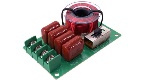
But the active/reactive ratio affects the circuit's Quality factor, i.e., its resonance. It's no coincidence that the knob on guitar amplifiers, which adjusts the same frequencies as our potentiometer or switch, is often called RESONANCE. And it is used to adjust to the resonance of the electromechanical system - the loudspeakers in the cabinet, along with the masses of air in and around it.
The reactive impedance accumulates energy and gives it away, except for losses due to dielectric recharging and magnetizing the magnetic core in inductors. This is why coreless inductors are often used in high-end equipment, so-called air inductors. They weigh a lot, take up a lot of space, and are expensive because copper is more expensive than steel. But these are the laws of physics on which technology is based.
Unlike reactive impedance, active resistance converts electrical energy into heat, thus reducing the Q-factor. In some cases, it is necessary and useful. In others, it is harmful. Or it simply creates a unique sound character.
That's why switching capacitors and turning the potentiometer knob in the feedback circuit of an audio frequency amplifier is almost the same thing, but not quite. And it's great that there are such different variants of guitar overdrive pedals!
Landtone Phoenix Song Overdrive
Now you can hear how my Zendrive from the Landtone OD-1 kit sounds, with a Seymour-Duncan SH4 humbucker on a Gibson MM Explorer guitar, into an Orange MT20 with a Torpedo Captor X. And see how I assembled the pedal and also a kitten walking around the table and prancing around.
youtube
I liked the pedal, especially its fourth magic Voicing knob, which does things to the sound that other tone controls can't. I also liked the bird on the body. Because I love birds. And in the music world, the decoration of instruments and hardware plays no small role because it inspires creativity. And the fact that the pedal is assembled by my hands also warms my soul and creates inspiration.
3 notes
·
View notes
Link
0 notes
Photo

I got some signal MOSFETs for smaller level shifting between a 3.3V microcontroller and the 5V WS2812 LEDs. In the middle is a 2N7000 in TO-92 package (good for through hole soldering) and on the right side the BSS138 (only available as SOT-23, so I needed an adapter for breadboard testing). For comparison a quite chunky standard logic level shifter/converter (4 lines plus power/ground). Both types work like a charm. So it's time to create a new revision of my PCB for the coffee notification button. Yay! #mosfet #bss138 #2n7000 #logic #levelshifter #converter #microcontroller #mcu #esp01 #esp8266 #esp8285 #arduino #ws2812b #led #lights #control #electronics #tinkering #soldering #hardwareporn #embedded #hardware #iot #tiny #hobby (hier: Lichtenberg, Berlin, Germany) https://www.instagram.com/p/BuhTTQCh9LN/?utm_source=ig_tumblr_share&igshid=5kiy4xm3x349
#mosfet#bss138#2n7000#logic#levelshifter#converter#microcontroller#mcu#esp01#esp8266#esp8285#arduino#ws2812b#led#lights#control#electronics#tinkering#soldering#hardwareporn#embedded#hardware#iot#tiny#hobby
0 notes
Photo

部品たったこれだけ #SHO 、大谷翔平じゃなくて #SuperHardOn 。 #MOSFET ブースター。石は #2N7000 。 #guitarpedals #make
0 notes
Photo

ARDUINO COMPONENTS
- Arduino Uno
- Breadboard
- 10k Thermistor
- DC Fan 12v
- 2N7000 Transistor
- Resistor 10k
- 12v Battery Pack
0 notes
Text
Moisture sensor -v3
Sensor power
As advised, I looked into using a MOSFET (2N7000) to switch power to the sensors. I struggled to make this work. Partly because my circuit was wrong to begin with (switch needed to go in the earth line to the sensors) but mostly because I couldn’t close the switch reliably in deep sleep leading to ongoing current draw ( I think). I also struggled with a bad moisture sensor which draw too much current. I discovered that using an LED in a circuit was a very simple way to estimate current flow.
In the end I settled for using two GPIOs, one to power the temperature sensors, the other for the moisture sensor. This also meant that power can be supplied to each in turn.
Deep sleep
On reset after deep sleep, setup() is run and then loop(). Since setup() is always run, it makes sense to do all the work in setup() with nothing in loop(). This is more flexible, for example so that the sensors can be powered on, read and processed and turned off before starting up the GSM chip.
RTC RAM
The effect of always running setup() is that all RAM state is lost. In this device there is nothing much to retain from cycle to cycle so it doesn’t really matter. However, the run time of each cycle can’t be reportet to the log because it needs to be included in the posted url and hence before transmission has been accomplished. It might also be useful to number the cycles.
The ESP32 has memory in the RTC clock and this persists through deep sleep. Variables declared as RTC_DATA_ATTR do persist which solves the problem. However the reported run time for a cycle is that of the previous cycle but this is still useful as a health indicator.
power consumption
The total runtime for GSM is around 23 seconds. In contrast the WiFi version runs for only 2 seconds. Ive havent yet been able to measure the current draw but it is going to be much greater for GSM.
One wire protocol
Ive added another sensor for the air temperature. The temperature sensors use the one-wire protocol which supports multiple sensors on the same pin. Each has a long address code which can be discovered and used to retrieve data, but there is also access by index from 0 upwards. I arbitrarily set the soil sensor to 0, air to 1. Then in calibration, I heat up one of them in my hand whilst watching the readings and then label the sensors appropriately.
camouflaged sensor
The first sensor to be depolyed in public is going to the Tiny Forest in Southmead. Here the leads and the control box can be hidden in the mulch. Further devices will be placed near street trees and here the box can be buried in the soil. Long leads will be nuisance so they are all reduced to 50cm. The plastic box fits into an old sock for disguise
Unified Wifi / GSM
To avoid multiple scripts I’ve now combined the WiFi and GSM versions into one - the latest version is on Github.
wiring
is much improved by more continuous testing of soldering and the purchase of a head magnifier - I feel like a proper electronics guy now! Thank the lord for a solder sucker too.


0 notes
Video
youtube
Tutorial for openoffice writer translating 诗篇 63 1 8 简体 中文 to english part 2
=========================================
Other items to offer :
Buy local , helps Australian grows

Lazer transmitter Module 1Pc

LM2596S ADJ DC-DC Step-down module 5V/12V/24V adjustable

0805 Capacitors with various value from 4.7pF to 1uF 10pcs /lot

Blue LED Crystal Clear 10Pcs

SMD RGB LED Module 1Pc

Through Hole Push Button 10Pcs

7 Color Flash Module 1Pc

RGB LED Module 1Pc

Reed Switch Module 1Pc

470uH 3A Power Supply Inductor 1Pcs
Offer :

3300uF 25V Power Capacitor 5Pcs

Electrolityc Capacitors with Multiple Values 0.47uF to 470uF

Small Signal Transistor With Various Value TO-92 Package ,
5Pcs Per Lot

1 Watt Zener Diode with Various Value 5Pcs Per Lot

Green Mylar Capacitor With Various Value 1nF-470nF, 5Pcs Per Lot

KBP307 Diode Rectifier 3A 700V 2100VA Max 2Pcs

Ultrasonic Speaker 2pcs

Low Voltage FET 2N7000 5 Pieces

10 Pieces 2N3904 Transistor

CR2 Battery for Photographer
0 notes
Text
Monday one
Lost a really long post to Tumblr that didn't make it online, don't know if my phone lost it , or if tumblr lost it, but either way kind of a disappointment.
Picked up some angle brackets for the laser harp hold the servo in place better so it doesn't vibrate seems pretty important. came home and hey I found some packets in he mail let's see what they are.
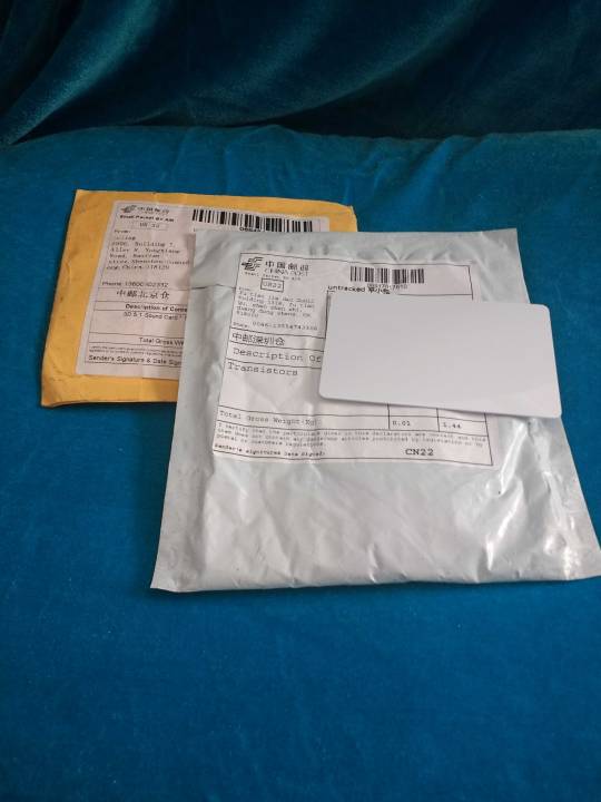


Looks like one got run over, but is okay. I'm going to use the little miniature sound card for a Raspberry Pi zero personal assistant project. The 2n7000 transistors are for a project that I'm working on with my good friend Dan. Dan's been my friend since middle school we live on different parts of the country now but I like to keep in touch when I can. The idea is to make it so that his smoke / carbon monoxide alarm will text him when it alerts. More on that later.
0 notes
Text
BS170
BS170 Small Signal MOSFET 500 mA, 60 Volts N−Channel TO−92 (TO−226)<br /><br />Useful for beacons as the Output FET, amplifier, level switch. Good for up to 250mW or even slightly more at HF.<br /><br />Do NOT use the substitute 2N7000 !! It is not pin compatible and can ruin your PCB.
View On WordPress
0 notes
Text
Conversor Bidireccional 3v3 - 5V

Conversor bidireccional com um simples mosfet 2N7000 para 3V3 e 5V - http://www.ptrobotics.com/product.php?id_product=1950
0 notes
Last Seen Blogs


gaysiancubb
💮m i g g y💮

chesspnoi-eaa
CHESSPNOI

gaymalebdsm
Untitled

gayjamesbond
ready when you are, sergeant pembry