#10 pin header connector
Explore tagged Tumblr posts
Text
https://www.futureelectronics.com/p/interconnect--rectangular-connectors/dt06-6s-te-connectivity-5076065
Wire to board connector, Electrical connector, wire connectors, Pin connectors
DT Series 6 Position Three Row Female Socket Free Hanging Plug Housing
#TE Connectivity#DT06-6S#Connectors#Rectangular Connectors#wire to board#Electrical connector#wire connectors#Pin#power connectors#10 pin header connector#cable connectors#connector housing#Industrial electrical connector#molex connector
1 note
·
View note
Text
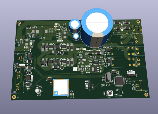
Let me introduce my current main WIP. It's not fandom related, it's for my model railroad, and it's not yet finished.
This is a rendering of a circuit board that I'm designing at the moment. It will be a DCC command station. My model railroad is run digitally, which means the tracks carry digital signals that tell each locomotive and switch individually how to run, which lights to turn and so on. The command station is the device that generates that. I have a number of different layouts, one of which has a good command station, one of which has a crappy old one, and the final one isn't even digital yet. So this will be the one that solves all issues for me, hopefully.
The design above isn't finished yet, and even the parts that are are not yet fully representative. The different capacitors are just there as options; some screen print overlaps; and some components (in particular all plugs and the relays that control the programming track) don't have 3D models so they don't show up.
Planned features:
Four layer board
10-25 V DC output, software controllable
Up to 5A output power, limited mainly by the main switching regulator.
Input 15-25V either AC or DC with polarity protection, selectable with some solder bridges (not yet in there). Optionally you can also bypass the main power regulator with another solder bridge (that I haven't added yet); useful in case you use e.g. a laptop power supply with a switchable voltage and don't need any regulation after that.
Railcom support
USB connection; not yet sure what for, but the main chip I'm using has USB support and I have some spare USB connectors here, so in it goes.
Speaking: The chip is an STM32L433RCT6P, chosen because I found it in stock at an electronics distributor. 64 kB RAM, 256 kB EEPROM, with support for an additional up to 256 MB externally (there's a spot for that on the board) and lots of fun extras that I don't technically need. It has an FPU! I don't need an FPU, but I will definitely do some floating point math computation on it just for fun.
Main external connection is WLAN using an ESP32 WROOM U module. I haven't decided on the housing, but I may go for extruded aluminum, so it's the U version that allows and requires an external antenna
It supports XBUS/XpressNet connections for old throttles from Lenz and Roco that I should probably throw away, but I paid good money for them, dang it.
It supports CAN for LCC / OpenLCB. I may not populate this part on all boards that I'm building, because I haven't actually decided whether I am interested. But the chip has CAN functionality built in, so why not.
There's an I2C connection to connect a cheap tiny OLED display for status messages.
Test points for all important signals (in particular the different internal voltage levels; yes, there is 3.3V, A3.3V and -3.3V and I need all of them).
Stuff still to add:
I will add pin headers (or space for pin headers anyway) for all the remaining pins on the STM32, and perhaps some on the ESP32, for future expansions.
Status LED and stop/go button on the front
Wire it all up, maybe move some stuff (mostly the STM32 around), which will cause all sorts of fun new routing issues.
Adjustments to make the jacks line up with the front panel once I've decided on a housing.
Features I'm not considering adding:
s88. I vaguely know what it is but I don't have any devices like that, and if that ever changed I could probably build (or perhaps buy) a converter that connects them via CAN.
Other buses like LocoNet.
Ethernet. I don't need it and it's actually more expensive than WLAN in this day and age.
In terms of software, I'm planning to use DCC-Ex on it. The whole project actually started out as a DCC-Ex shield, but once I realised that this wouldn't fit, I decided to make it standalone. Now, DCC-Ex is designed for Arduino, not STM32, and it doesn't support XpressNet, nor OpenLCB, nor Railcom, and their Wifi protocol is pretty weird and annoying which will be an issue (I'm planning to write my own control app for iPhone for it), so I'll probably change that or just replace it with the z21 one… so really, the software will not look a lot like DCC-Ex once I'm done with it.
Will this all work? I have honestly no idea. I mean, I'm fairly confident, I'd have given up on this long ago otherwise, but I have no guarantees either way until I've spent a lot of money on components and circuit boards and start soldering. Turns out doing it this way is not really cheaper than just buying a half-way decent one. That's what makes it exciting, though!
If it does work, obviously this will be released as open source. But it's still going to be a few days (more realistically weeks) before it's even ready to order the parts, and then a lot of soldering (current BOM stands at 194 actual components), and then a lot of software development before it's ready for that.
5 notes
·
View notes
Text
Buy HC05 Bluetooth Module at Affordable Price in Ainow
HC05 Bluetooth Module
The Bluetooth Transceiver HC05 bluetooth Module with enable/disable button Breakout is the latest Bluetooth wireless serial cable! This version of the popular Bluetooth uses the HC05 module. These modems work as a serial (RX/TX) pipe. Any serial stream from 9600 to 115200bps can be passed seamlessly from your computer to your target. The remote unit can be powered from 3.3V up to 6V for easy battery attachment. All signal pins on the remote unit are 3V-6V tolerant. No level shifting is required. Do not attach this device directly to a serial port. You will need an RS232 to TTL converter circuit or Arduino XBee USB Adapter if you need to attach this to a computer. You can either solder a 6-pin header or individual wires. The unit comes without a connector. Please see related male and female pins below. And now, we provide HC-05/06, HC05 bluetooth module could be set to Master or Slave by a user. HC-06 just be Master or Slave, that could be customized.
HC05 bluetooth module Applications:
Embedded Projects
Industrial Applications
Computer and portable Devices
GPS receiver.etc.
Note: Product Image may vary in terms of design and colour of the board
Features :
CSR Bluetooth Chip Solution-Bluetooth Spec v2.0 EDR Compliant
Enhanced Data Rate (EDR) compliant with V2.0.E.2 of the specification for both 2Mbps and 3Mbps modulation modes
Full Speed Bluetooth Operation with Full Piconet Support and Scatternet Support
Incredible small size with 3.3V input, and RoHS Compliant-UART interface and with baud rate setup function
Support for 8Mbit External Flash Onboard Support for 802.11Co-Existence. A range of operation: 8 – 10 meter.

0 notes
Text
DIY: Flipper Zero Quick Prototype Module
Tinkering with Flipper Zero and adding various modules have been fun, but I found doing it with breadboard and jumper wires have been rather messy and it's difficult to bring the add-on around with wires and components hanging off the Flipper Zero. So, I decided to spend a couple of hours to put together a quick prototype module with breadboard attached that plugs into Flipper Zero. I also added an AMS1117 5v to 3.3v step down power supply buck to the board, so that 3.3v also comes from the 5v pin. This makes the module hot pluggable as long as you don't use the Flipper Zero's 3.3v pin. It's a lot more convenient this way. Here's the final result! What do you think?
Now I can try out quick builds of various projects and bring it around to test it with no issue, before committing to a design and making it permanent. Here are more examples using this quick prototype module.
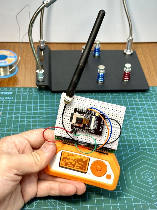
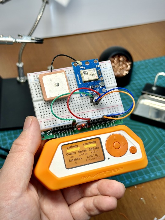

It just cost me a few bucks for the parts and I think it's time well spent. If you wish to make one yourself, here's a quick guide below.
Build Steps
Here are the stuff you will need for this project: An 8cm x 6cm double sided prototype board, a 400 hole breadboard, some 25mm male and female header pins, some jumper wires and an AMS1117 5v to 3.3v step down power supply buck. These can be found in Aliexpress, Amazon, Lazada, etc.

First, cut away the connectors on the side of the breadboard just to give it a cleaner look.

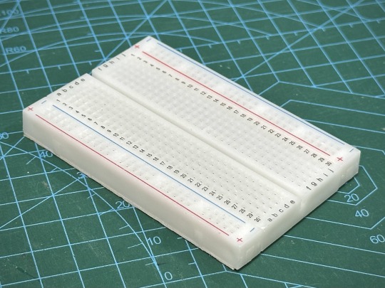
Next is to cut the female header pins to the right length, or you can just get the right sizes of the shelf. You need one with 8 pins and another one with 10 pins.

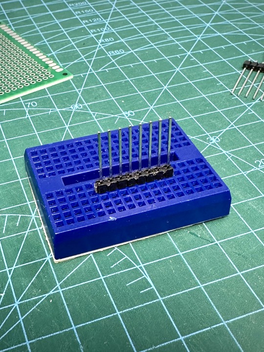
Next, we need to cut the male header pins to length. Again, we need one with 8 pins and one with 10 pins. After that, stick the header pins all the way into a breadboard, then use a ruler/screwdriver to slowly push the plastic thingy holding the pins down until it touches the breadboard.

Use a masking tape to mark the pin at 5mm above the plastic thingy. This is the line where you will bend the pins.

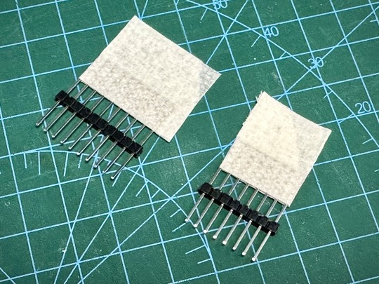
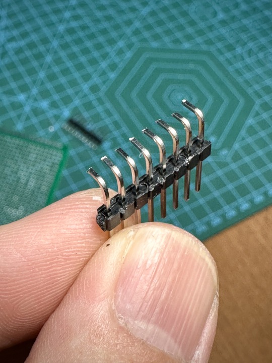
Now use a plier to bend the pins 90 degrees, then cut the pins shorter like below. You can cut the pins after soldering it on to the board, but I find it easier to cut it before.


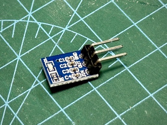
Next, we work on the power supply step down module. You need to remove the plastic thingy from the pins. Just use a cutter to trim it off, then bend the pins straight.

Now you can solder the male header pins to the prototype board like below. You can also see how the female header pins should be placed on the board.
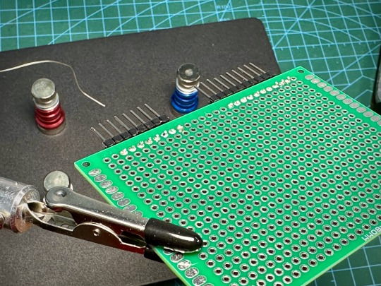
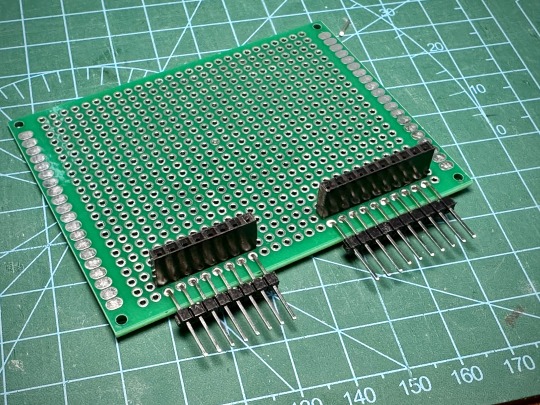
Bend the legs of the female header pins so that they lean towards the solder points of the male header pins, then solder each corresponding pin to bridge them together.

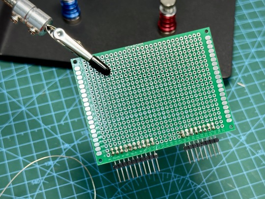
Now go ahead and also solder the power supply module and wire them accordingly. Note that I also cut a 2 pin female header and I wired both to the 3.3V VOUT from the power supply module.
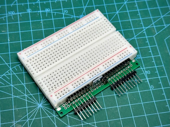
At this point, it's probably good to take out the multimeter (or use the continuity tester app on Flipper) to test all the connections to make sure all the connections are good and that there are no shorts. After that, peel off the tape backing from the breadboard and stick it on the module.
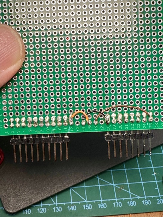
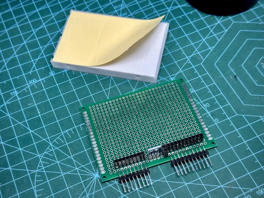
That's it! You're done, and now you have a nifty quick prototyping module for your Flipper Zero that will make your experimenting a lot more enjoyable.

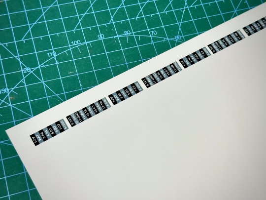
Oh, and just one more thing ... I designed and printed some stickers to label the pins on the module. This makes it a lot less likely that you will stick the connections in the wrong holes. You can download the PDF for the stickers here.
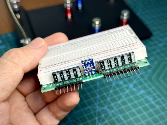
There, now we are really done. Let me know what you think, or how I can improve this. Have fun! If you enjoy stuff like this, check out our Makers & Hackers Exchange Facebook group.
0 notes
Photo

Senseair K30 CO2 meter Hi, I’ve installed a Senseair K30 CO2 meter to an ESP32 and i’d like to share this with you. Big thanks to martgras and znerk13 for showing the way (Add Senseair K30 CO2 sensor · Issue #1587 · esphome/feature-requests · GitHub). Starting off with the most important question first: why choose the expensive Senseair K30 sensor, and not something else? The choice is based on this scientific publication, which shows the K30 to be a very good sensor. Tomomi Yasuda et al, Comparison of the Characteristics of Small Commercial NDIR CO2 Sensor Models and Development of a Portable CO2 Measurement Device, Sensors 2012, 12, 3641-3655 The result is backup-up by this peer-reviewed paper: Cory R. Martin et al, Evaluation and environmental correction of ambient CO2 measurements from a low-cost NDIR sensor, Atmos. Meas. Tech., 10, 2383–2395, 2017. The result is also backup-up by this non-peer-reviewed paper, which also shows the K30 to be a good sensor: Mengna Li et al, Design of a Calibration System for Miniature Carbon Dioxide Sensors, FLOMEKO 2019, Lisbon, Portugal Okay, based on these results, i choose the Senseair K30. The K30 uses automatic baseline calibration (ABC) to auto-calibrate every 7.5 days. It assumes that lowest measurement in this period is the baseline value of 400 ppm. This mechanism works fine unless somebody is at home all the time (the baseline of 400 would never be reached in those 7.5 days). If the baseline is never reached, it is also possible to disable the ABC-mechanism, but i have not investigated this. Hardware: Power Supply: Mean Well RS-15-5 ESP32: ESP32 WROOM Devkit CO2 sensor: Sensair K30 Bi-directional Logic Level Shifter 3.3v 5v The sensor is very flexible, it can be connected analog and digital via I2C and UART (modbus). I choose UART based on the previous work of martgras and znerk13. Dupont pin headers are soldered onto the Senseair K30 UART terminal. In he picture below, from left to right: ground, 5v, RX, TX From here, the RX and TX go to the Logic Level Shifter → ESP32 TX (GPIO1, orange cable) and RX (GPIO3, yellow cable). As always, RX from the sensor goes to TX of the ESP and TX from the sensor goes to RX of the ESP. Screw the ESP into a project box and fixate the logic level shifter inside. Use a cable gland to fixate cabling in the project box. Now, screw the Senseair K30 outside of the project box, on top of the lid. Make sure to only use two screws, not more. Reason: Senseair advices this to prevent strain on the pcb. Also make sure that both screws are isolated from each other and isolated from main ground (for example by using plastic screws). Connect the wires and screw the top on the project box. CO2 sensors are sensitive to temperature, therefore the ESP32 is inside the box and the sensor is outside of the box attached via spacers. This is also the reason why the power supply is in another location. Building the power supply: this is pretty standard stuff. Crimp ring (or fork-style) connectors to the cables and screw the cables to the power supply. The power supply is placed into a ventilated project box (you can drill holes for this). Make sure to use cable glands to secure the 230v cables, otherwise you are creating a very dangerous situation. Use thick cabling to go from the power supply to the esp32/K30 combination to prevent voltage drop. I’ve used 0.75mm squared cables. You can calculate the required wire thickness using this website: Voltage Drop Calculator Inside the esp32 project box, i’ve placed Wago 221 to divide the cables further into shorter smaller cables to which i crimped dupont connectors (for the ESP32 and the K30) and ferrules (for the Wago 221). End-result of the device. Again, please be aware to place the power supply away from the K30 sensor to prevent warm-up and drifting CO2 measurements. I’ve placed the device inside the ventilation shaft that is extracting air from my living room to the outside. ESPHome is installed onto the ESP32. See the config below. esphome: name: living-room-co2-meter friendly_name: Living Room CO2 Meter comment: ESP32ESP-32S Wroom Devkit v1 + Senseair K30 esp32: board: esp32dev framework: type: arduino # Enable logging logger: baud_rate: 0 # Enable Home Assistant API api: encryption: key: "xxx" ota: password: "yyy" wifi: ssid: !secret wifi_ssid password: !secret wifi_password # Enable fallback hotspot (captive portal) in case wifi connection fails ap: ssid: "Living-Room-Co2-Meter" password: "zzz" captive_portal: uart: id: mod_uart tx_pin: 1 rx_pin: 3 baud_rate: 9600 stop_bits: 1 parity: none modbus: send_wait_time: 200ms uart_id: mod_uart id: mod_bus modbus_controller: - id: sensek30 ## the Modbus device addr address: 0xFE modbus_id: mod_bus command_throttle: 500ms setup_priority: -10 update_interval: 30s sensor: - platform: modbus_controller modbus_controller_id: sensek30 id: status_raw name: "CO2 Status Raw" internal: True address: 0 register_type: "read" value_type: U_WORD accuracy_decimals: 0 - platform: modbus_controller modbus_controller_id: sensek30 id: co2 name: "CO2 Level" address: 3 unit_of_measurement: "ppm" register_type: "read" value_type: U_WORD accuracy_decimals: 0 text_sensor: - platform: template name: "CO2 Status" lambda: |- if (id(status_raw).state == 0) { return {"Ok"}; } if (id(status_raw).state == 1){ return {"Error"}; } else { return "Unknown Code: " + to_string(id(status_raw).state); } The end-result is looking very good. 1 post - 1 participant Read full topic https://community.home-assistant.io/t/senseair-k30-co2-meter/593808
0 notes
Text
Header plug socket, Socket Plug, connector pin socket, receptacle socket
6.35 mm Quick Connect Female and Male 10-14 AWG Crimp Connector Non-Insulated
#TE Connectivity#62253-2#Connectors#Pin and Socket Connectors#Pin Contacts#Header plug socket#Socket Plug#connector pin socket#receptacle socket#Circular connector#board mount sockets#Crimp Terminals#edge connector#socket mount wire
1 note
·
View note
Text
New Product has been published on GamersFlix
New Product has been published on https://gamersflix.com/product/h61m-s1-mainboard-rd-h61-socket-lga-1155/
H61M-S1 Mainboard Rd H61 Socket LGA 1155
H61M-S1 Mainboard Rd H61 Socket LGA 1155
Features: 1. CPU: Supports Intels Core i7/i5/i3/Pentium/Celeron processors in LGA1155 package. Chipset, Intels H61 Express Chipset. 2 1.5V DDR3 DIMM slots support up to 16GB of system memory dual channel memory architecture. Supports DDR3 1333/1066/800 MHz memory modules. 2. Audio: High-end audio codec. 2/4/5.1/7.1 HD audio. LAN: 1 x Realtek RTL8111E chip (10/100/1000Mbit). The new era of digital power design fully realizes excellent system stability, great power efficiency, and improved performance scaling. 3. Expansion Slots: 1 x PCI Express x16 slot, running in x16 2 x PCI Express x1 slot. Real-time network bandwidth control application that allows users to assign bandwidth priorities to different applications. 4. Storage Interface: 4 x SATA 3 Gb/s connectors Supports up to 4 SATA 3 Gb/s devices. USB is Up to 8 USB 2.0/1.1 ports. Real-time energy management and power saving system for superior platform energy efficiency. 5. Internal I/O Connectors: 1 x ATX 24-pin main power connector/ 1 x 4-pin ATX 12V power connector/ 4 x SATA 3Gb/s connectors/ 1 x system CPU fan header/ 1 x fan Connectors/ 1 x Front Panel Connector/ 1 x Audio Front Panel Connector/ 2 x USB 2.0 / 1.1 / 2 x Connectors/ 1 x Parallel Port Connector/ 1 x Serial Port Connector/ 1 x Clean CMOS Jumper. Rear Panel Connectors: 1 x PS2 Keyboard Port/1 x PS2 Mouse Port/1 x D-Sub Port/4 x USB 2.0/1.1 Ports/1 x RJ-45 Port/3 x Audio Jacks (Line /line-out/mic).
Description: The mainboard supports Intels Core i7/i5/i3/Pentium/Celeron processors in the LGA1155 package. Chipset, Intels H61 Express Chipset. 2 1.5V DDR3 DIMM slots support up to 16GB of system memory dual channel memory architecture. Supports DDR3 1333/1066/800 MHz memory modules.
Specifications: Material: Plastic Dimensions: 22.6×17.4cm Memory capacity: 16GB Model: H61M-S1 Chip: Integrated 8-channel audio chip LGA 1155: H61 memory Channel: Dual Channel Display interface: VGA multi-graphics card Support: not supported Applicable object: Desktop Whether to support display output: Yes Whether to support disk array: not supported CPU type: intel CPU interface type: intel LGA 1155 Number of network cards supported: single network card
Package Included: 1pc *Disassembly Board
Notes: 1. Please allow 0-1 inch error due to manual measurement. Thanks for your understanding. 2. Monitors are not calibrated the same, the item color displayed in photos may be showing slightly different from the real object.


0 notes
Text
Deepcool Infinity LS720 ARGB AIO Liquid Cooler Features: The DeepCool LS720 premium liquid CPU cooler maximizes cooling performance and low-noise efficiency with a 360mm radiator, two FC120 A-RGB PWM fans, and an infinity mirror cap design. A NEW ERA OF DEEPCOOL Built on our 4th Generation high-performance water pump that maximizes cooling performance featuring: Improved microchannel design ensures optimal coolant flow. Powerful three-phase drive motor up to 3100 RPM.  Thick solid copper base with a seamless match. COOL AND QUIET Get treated to excellent cooling and superb silent efficiency with the included FC120 fans boasting enhanced static pressure, concentrated airflow, and a fluid dynamic bearings. SIMPLE AND SECURE Installation is quick and easy with newly designed mounting brackets that keep your cooler fastened safely on both Intel and AMD platforms. INTELLGA2066/2011-v3/2011/1700/1200/1151/1150/1155 AMDsTRX4/sTR4/AM5/AM4 CUSTOMIZE YOUR LOOK The new infinity mirror pump face design projects two light loops for a mesmerizing visual effect while also allowing installation in any orientation with a independently rotatable logo plate. For full customization, an additional blank plate is provided for your own design. SYNCHRONIZE YOUR SETUP WITH RGB LIGHTING EFFECTS Coordinate your colors through supported RGB software and motherboard synchronization to access control for different lighting effects. A default Auto-RGB rainbow effect is enabled when no controller is detected allowing limited functionality on motherboards without 5V A-RGB headers. Deepcool Infinity LS720 ARGB AIO Liquid Cooler Specification: Model R-LS720-BKAMNT-G-1 Color Black Application For Intel LGA2066/2011v3/2011/1700/1200/1151/1150/1155 AMD sTRX4/sTR4/AM5/AM4 Net Weight 1607 g Radiator Dimensions 402×120×27 mm Radiator Material Aluminum Tube length 410 mm Pump Dimensions 86×74×57 mm Pump Speed 3100 RPM±10% Pump Noise 19 dB(A) Pump Connector 3-pin Pump Rated Voltage 12 VDC Pump Rated Current 0.47 A Pump Power Consumption 5.64 W Fan Dimensions 120×120×25 mm Fan Speed 500~2250 RPM±10% Fan Airflow 85.85 CFM Fan Air Pressure 3.27 mmAq Fan Noise ≤32.9 dB(A) Fan Connector 4-pin PWM Bearing Type Fluid Dynamic Bearing Fan Rated Voltage 12 VDC Fan Rated Current 0.29 A Fan Power Consumption 3.48 W LED Type Addressable RGB LED LED Connector 3-pin(+5V-D-G) LED Rated Voltage 5 VDC LED Power Consumption 2.2 W(PUMP)/ 3.6 W(FAN×2) Warranty 3 Years Note *** Features, Price, Specifications are subject to change without notice. WARRANTY3 Years
0 notes
Text
ROG CROSSHAIR VIII HERO (WI-FI)
CPU AMD AM4 Socket third and second AMD Ryzen/second and first Gen AMD Ryzen with Radeon Vega Graphics Processors Refer to for CPU bolster list Chipset AMD X570 Memory third Gen AMD Ryzen Processors 4 x DIMM, Max. 128GB, DDR4 MHz Un-supported Memory second Gen AMD Ryzen Processors4 x DIMM, Max. 128GB, DDR4 MHz Un-supported Memory second and first Gen AMD Ryzen ROG CROSSHAIR VIII HERO (WI-FI) with Radeon Vega Graphics Processors4 x DIMM, Max. 128GB, DDR4 MHz Un-cradled Memory Dual Channel Memory Architecture ECC Memory (ECC mode) support differs by CPU. Allude to for the Memory QVL (Qualified Vendors Lists). Multi-GPU Support third and second Gen AMD Ryzen Processors Supports NVIDIA 3-Way SLI Technology Supports AMD 3-Way CrossFireX Technology second and first Gen AMD Ryzen with Radeon Vega Graphics Processors Supports AMD 2-Way CrossFireX Technology Expansion Slots third Gen AMD Ryzen Processors 2 x PCIe 4.0 (x16 or double x8) second Gen AMD Ryzen Processors2 x PCIe 3.0 (x16 or double x8) second and first Gen AMD Ryzen with Radeon Vega Graphics Processors1 x PCIe 3.0 x16 (x8 mode) AMD X570 chipset1 x PCIe 4.0 x16 1 x PCIe 4.0 x1 Storage third Gen AMD Ryzen Processors : 1 x M.2_1 attachment 3, with M Key, Type 2242/2260/2280 (PCIE 4.0 x4 and SATA modes) stockpiling gadgets support2nd Gen AMD Ryzen/second and first Gen AMD Ryzen with Radeon Vega Graphics Processors : 1 x M.2_1 attachment 3, with M key, type 2242/2260/2280 capacity gadgets support (SATA PCIE 3.0 x 4 mode) AMD X570 chipset : 1 x M.2_2 attachment 3, with M Key, ROG CROSSHAIR VIII HERO (WI-FI) Type 2242/2260/2280/22110(PCIE 4.0 x4 and SATA modes) stockpiling gadgets support8 x SATA 6Gb/s port(s), Support Raid 0, 1, 10 LAN Intel I211-AT Realtek RTL8125-CG 2.5G LAN ASUS LAN Guard ROG GameFirst Technology Wireless Data Network Supports channel transmission capacity: HT20/HT40/HT80/HT160 Intel Wi-Fi 6 AX200 2 x 2 Wi-Fi 6 (802.11 a/b/g/n/air conditioning/hatchet) with MU-MIMO bolsters double recurrence band 2.4/5GHz Up to 2.4Gbps exchange speed Bluetooth 5.0 Audio ROG SupremeFX 8-Channel High Definition Audio CODEC - Impedance sense for front and back earphone yields Supports : Jack-location, Multi-streaming, Front Panel Jack-retasking-High quality 120 dB SNR sound system playback yield and 113 dB SNR recording input-SupremeFX Shielding Technology-ESS ES9023P-Supports up to 32-Bit/192kHz playback Audio Feature : - Sonic Studio III + Sonic Studio Virtual Mixer-DTS Sound Unbound - Optical S/PDIF out port(s) at back board Sonic Radar III Due to confinements in HDA transfer speed, 32-Bit/192kHz isn't upheld for 8-Channel sound. USB Ports third Gen AMD RyzenTM Processors : 4 x USB 3.2 Gen 2 port(s) second Gen AMD RyzenTM/second and first Gen AMD Ryzen with Radeon Vega Graphics Processors : 4 x USB 3.2 Gen 1 port(s) AMD X570 chipset : 1 x USB 3.2 Gen 2 front board connector port(s) AMD X570 chipset : 4 x USB 3.2 Gen 2 port(s) AMD X570 chipset : 6 x USB 3.2 Gen 1 port(s) AMD X570 chipset : 4 x USB 2.0 port(s) ROG Exclusive Features Extreme Engine Digi+ : - IR3555 PoweIRstage-MicroFine Alloy Chokes-10K Black Metallic CapacitorsROG Extreme OC unit :- OptiMem III-Safe Boot button-Slow Mode-LN2 Mode Extreme TweakerROG Patented Pre-mounted I/O ShieldROG Exclusive Software-Sonic Studio III + Sonic Studio Virtual Mixer-RAMCache III-RAMDisk-CPU-Z-GameFirst V-Sonic Radar III Special Features ASUS Dual Intelligent Processors 5-Way Optimization by Dual Intelligent Processors 5 : - 5-Way Optimization tuning key impeccably merges TPU, EPU, DIGI+ VRM, Fan Expert 4, and Turbo AppAURA : - Aura Lighting Effects Synchronization with good ASUS ROG devicesASUS Exclusive Features : - USB BIOS Flashback-AI Suite 3-Ai Charger - ASUS CrashFree BIOS 3 - Armory Crate-ASUS NODE: equipment control interface-ASUS EZ Flash 3 - ASUS C.P.R.(CPU Parameter Recall) - Clear CMOS Button - Reset Button - Start Button-ReTry buttonASUS Q-Design : - ASUS Q-Code-ASUS Q-LED (CPU, DRAM, VGA, Boot Device LED) - ASUS Q-Slot-ASUS Q-DIMM - ASUS Q-Connector Back I/O Ports 1 x Optical S/PDIF out 1 x Clear CMOS button(s) 1 x Anti-flood 2.5G LAN (RJ45) port1 x USB BIOS Flashback Button(s) 1 x ASUS Wi-Fi Module5 x Gold-plated sound jacks4 x USB 3.2 Gen 1 (up to 5Gbps) ports 8 x USB 3.2 Gen 2 (up to 10Gbps) ports ()Anti-flood LAN (RJ45) port Internal I/O Ports 2 x Aura RGB Strip Headers 2 x Addressable Gen 2 header(s) 2 x USB 2.0 connector(s) support(s) extra 4 USB 2.0 port(s) 1 x M.2 Socket 3 with M key, type 2242/2260/2280 capacity gadgets support1 x M.2 Socket 3 with M key, type 2242/2260/2280/22110 capacity gadgets support1 x TPM connector(s) 8 x SATA 6Gb/s connector(s) 1 x CPU Fan connector(s) 1 x CPU OPT Fan connector(s) 3 x Chassis Fan connector(s) 1 x AIO_PUMP connector 1 x H_AMP fan connector 1 x W_PUMP+ connector 1 x 4-pin EATX 12 V Power connector1 x 24-pin EATX Power connector(s) 1 x 8-pin EATX 12V Power connectors1 x Front board sound connector(s) (AAFP) 1 x Slow Mode switch(es) 1 x Reset button(s) 1 x Node Connector(s) 1 x LN2 Mode jumper(s) 1 x Safe Boot button1 x ReTry button1 x System board connector1 x T_Sensor Connector1 x W_IN header1 x W_OUT header1 x W_FLOW header1 x Start button1 x Speaker connector1 x USB 3.2 Gen 2 (up to 10Gbps) connector1 x USB 3.2 Gen 1 (up to 5Gbps) connector bolster extra 2 USB ports Accessories Users manual 4 x SATA 6Gb/s cable(s) 1 x M.2 Screw Package1 x Supporting DVD1 x ROG huge sticker1 x Q-Connector1 x Wi-Fi Antenna(s) 1 x Extension Cable for RGB strips (80 cm) 1 x Extension link for Addressable LED1 x ROG coaster(s) 1 x ROG Thank you card BIOS 256 Mb Flash ROM, UEFI AMI BIOS, PnP, WfM2.0, SM BIOS 3.2, ACPI 6.2 Manageability WOL, PXE Operating System Windows 10 64-piece Form Factor ATX Form Factor 12 inch x 9.6 inch ( 20.5 cm x 24.4 cm )
1 note
·
View note
Photo


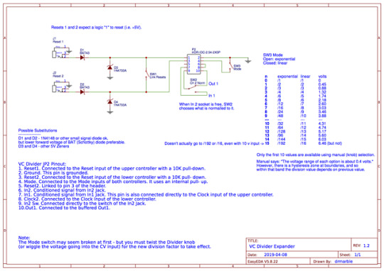
Expander Module for the SSSR VC Divider.
I built the VC Divider last year, and I have since found a lot of use for it in generative synth patches, to divide clock and trigger signals down. It has an onboard 10-pin header that can be used to configure some options by using jumpers. But it was also well-documented so that I could create an expander module to make all those options readily available. After designing the expander circuit, I built it onto a 3hp panel. (In case you’re wondering, it may have been possible to squeeze it onto a 2hp, but the top toggle switch might not have had enough space then for the adjacent ribbon cable header that protrudes somewhat behind the expander panel.) The circuit is passive, so no power connector is needed.
I highly recommend using a rainbow ribbon cable for this project - the color coding makes it so much easier to keep track of the wires.
Don’t forget the ground connection to the local ground (I did at first!). The expansion jumper has ground on pin 2 (here, the red wire of the rainbow ribbon cable). So I ran a small jumper wire from the toggle’s top lug to the “sleeve” lug of the closer jack. It’ll still work without that wire in place, but you want to ensure that the input protection diodes (D3 and D4) have a path to ground no matter what.
Oh, and labeling was done with a Brother P-touch labelmaker, using 6mm black-on-clear tape. I kept the labels long so I could wrap them around the sides, just makes it look a little neater.
1 note
·
View note
Text
Pl usb blaster rcn


The 3kW high voltage (HV) DC power supplies offers 90 to 264Vac input and a choice of regulated, si. This device links your PC to a 10-pin header connected to your FPGA and will allow you to send. “This means that applications such as battery charging can be addressed without having to split the. The Altera USB Blaster is a great FPGA programming device. The Prime Minister announced the £24.1bn spending, over the next 4 years, addressing national defen.
RAF Space Command to be established, launching in Scotland.
With a SpaceX Falcon 9 successfully completing the launch, the new satellite – the latest in a seri.
Copernicus Sentinel-6 satellite launches to monitor sea levels.
The small satellites will be built as part of a new three-year project entitled xSPANCION. By using the Co-Browse feature, you are agreeing to allow a support.
AAC Clyde Space UK signs deal for 10 Glasgow-built xSPANCIO.
2:1 MIPI switch for 2x data + 1x clock D-PHY, or 2x C-PHYĬalled PI3WVR628, it is a six channel single-pole, double-throw (SPDT) switch supporting two data.
There are 32 products in the TCR3RM series, as it will be known, with single fixed outputs spanning. The aim is that the sensors will improve scientifc understanding of upper atmospheric dynamics and d.

Cold Atom Space Payload Accelerometer aims to advance clima.
The caps are IP67 rated and help prevent the build-up of moisture, dust, and dirt in the connector’.
Altera (Intel® Programmable Solutions Group) Distributor SPW Industrial warrants this product to be free of defects in workmanship and material under normal use and conditions for period of one year from the date.
Altera (Intel® Programmable Solutions Group) Supplier.
Buy Altera (Intel® Programmable Solutions Group) PL-USB2-BLASTER.
Altera (Intel® Programmable Solutions Group) PL-USB2-BLASTER.
Please feel free to contact us if you have any questions about the shipment. ★ĝelivery time will need 2-4 Days to most of country all over the world by DHL/UPS/FEDEX/TNT. (ONLY FOR Integrated Circuits, Circuit Protection, RF/IF and RFID, Optoelectronics, Sensors, Transducers, Transformers, Isolators, Switches, Relays)įrom $35.00 basic shipping fee depend on zone and country.
★ğREE SHIPPING VIA DHL/FEDEX/UPS IF ORDER AMOUNT OVER 1,000 USD.
If the products are defective or they don't working, you can return to us within 1 YEAR, all transportation and customs charges of the goods are borne by us. If you find quality problems about our products after receiving them, you could test them and apply for unconditional refund if it can be proved. During this period, we could provide free technical maintenance if there are any problems about our products. Each product from has been given a warranty period of 365 days.

0 notes
Text
50 pin molex connector

#50 pin molex connector full
#50 pin molex connector series
Product Pictures Molex 2. Service: Wiring Harness OEM Certificate: CE, RoHS Pin & Socket Connectors PLUG WHITE 94V-0 420 WHITE 94V-0 4202106. Temperature operating temperature, fixed installation: -40☌ to +105☌ Electrical Performance: Rating voltage: 300V AC Rating Current: 3A (22AWG)Ģ.
#50 pin molex connector series
SL Crimp Terminal, Series 70021, Male, ReelĠ.38µm Selective Gold (Au) Plated Contactġ. of 170 watts 50-1037 Transformer/Barrel Jack Male Adapter Cable - Power. SL Crimp Terminal, Series 70021, Male, Reel Packing 6 (+2) pin PCIe connector, a SATA connector, and a Molex connector contents. With its large number of options and configurations, SL Modular Connectors and Assemblies deliver ideal wire-to-wire solutions and its varying PCB termination methods, including reflow process capable versions, support a range of wire-to-board applications.ġ.1 Molex 70400 Series SL 2.54mm pitch wire-to-wire connector housing The Connector housing is male, single row, version A, without mounting ears, 3 circuits, black. China Shenzhen Xaja 50 Pin 30pin to 20 Pin LG LCD Hirose Molex Jst Connector Lvds Cable Type, Find details about China Jst Connector Lvds, Hirose Lvds Cable from Shenzhen Xaja 50 Pin 30pin to 20 Pin LG LCD Hirose Molex Jst Connector Lvds Cable Type - Shenzhen Xi Ang Ju An Electronic Co., Ltd. 50-57-9407 - Molex Heilind Electronics We use cookies to make your experience better. Estimated manufacturer lead time is for quantities greater than shown above. 50-57-9407 - Pin and Socket Housings by Molex at Heilind 1 distributor of connectors, relays, sensors, switches and other electronic components. Molex pins we used were P/N 08-50-0113, and they work with the KK series. 50-84-2150 from Molex Incorporated at Allied Electronics & Automation. Molex SL 70107-0002 3 Pin 2.54mm Pitch Wire-to-Wire Connector Cable AssembliesįLECONN can custom molex sl 70107-0002 2 3 4 5 6 7 8 9 10 11 12 pin 2.54mm pitch wire-to-wire connector cable assemblies. Similarly, you can add Molex connectors to Power Functions wires. 240 V ac at 50/60 Hz Server Power Supply Pinout - Simon Wyss Fortunately.
Waterproof Enclosures/ Housing/ Box Design Buy it with This item: Molex Connector Housing, Plug, 9Pos - 50-84-1090. A qualified PMC IEEE 1386 standard connector that provides a rugged housing and protected pin interface for reliable signal transmission, a slim-body housing that minimizes airflow obstruction and the versatility to be arrayed to increase circuit size. pin MOLEX 39-29-9202 connector and 20 pin MOLEX 39-01-2200 connectorThis.
#50 pin molex connector full
Connectors & Cables Connectors PCB Connectors Pin Headers, Receptacles systems Molex FFC/FPC connector Total number of pins 50 Contact spacing: 0.5 mm 5019515000 2000 pc(s) Tape on Full reel. Jack & DC Plug for IRIS auto camera lens Molex FFC/FPC connector Total number of pins 50 Contact spacing: 0.5 mm 512965094 3000 pc(s) Tape on Full reel. Back to Pin Headers, Receptacles systems.If it is determined during the customer’s evaluation of suitability, that higher performance is required, please contact Molex for possible product options. 6 YRS 4.9 (7) Contact Supplier 1 / 6 Custom auto wire harness 30 40 50 pins with connectors auto electrical pin connector 1.00-8.00/ Piece 1 Piece (Min. The Connector housing is female, single row, version C. Order) CN Dongguan Lanbo Electronics Technology Co., Ltd. FLECONN can assemble molex 2.54mm pitch 70066 series 50-57-9212 sl 12 pin connector wire harness. The customers using this product must determine its suitability for use in their particular application through testing or other acceptable means as described in end-product glow-wire flammability test standard IEC 6 and any applicable product end-use standard(s). 50 Pin Right Angle Male Shrouded PCB IDC Socket Box header Electrical Connector for Cars 0.06-0.30/ Piece 1000 Pieces (Min. This Molex product is manufactured from material that has the following ratings, tested by independent agencies :Ī) A Glow Wire Ignition Temperature (GWIT) of at least 775 deg C per IEC 6.ī) A Glow Wire Flammability Index (GWFI) above 850 deg C per IEC 6.and hence complies with the requirements set out in the International Standard IEC 60335-1 5th edition - household and similar electrical appliances - safety section 30 Resistance to heat and fire.

0 notes
Text
How to change nat type to open on a netgear router r7000

How to change nat type to open on a netgear router r7000 serial#
How to change nat type to open on a netgear router r7000 Patch#
How to change nat type to open on a netgear router r7000 pro#
How to change nat type to open on a netgear router r7000 windows#
Using a browser set to 192.168.1.1 on the MacBook Pro, log into the Netgear R7000 router web configuration page. Wait until you see that the firmware upload was successful (about 90 seconds) and then wait for the router to fully reboot (another 150 seconds).ġ5. Afterward move focus to the Terminal window and paste in the commands in item 10 that you copied earlier.ġ4. The router hardware will start flashing a LED signaling it is ready for a tftp upload.
How to change nat type to open on a netgear router r7000 serial#
When you see the CFE> prompt in the Serial window, type in tftpd into the window and return. Power up the Netgear R7000 and immediately start submitting ^Cs repeatedly to Serial until a CFE> prompt comes up.ġ3. Click on the Serial window so typing is directed to that window.ġ2.
How to change nat type to open on a netgear router r7000 windows#
Shrink or close all windows except Terminal and Serial and position both to be visible on the screen. Into the copy/paste buffer on the MacBook Pro, copy the following list of commands:ġ1. Launch Terminal on the MacBook Pro, cd to the directory that contains the factory-to-dd-wrt.chk firmware image you want to upload.ġ0.
How to change nat type to open on a netgear router r7000 pro#
Launch the Serial Terminal Emulator on the MacBook Pro and configure it to use the Ftdi - TTL-232r-3v00-8-N-1. Using System Preferences, define the MacBook Pro's USB Ethernet adapter to configure its IPv4 manually, with its IP address to be: 192.168.1.44, Subnet Mask: 255.255.255.0, and Router: 192.168.1.1ĩ. Attach the newly rearranged plastic connector to match the header pins on the motherboard.Ĩ. The three pins of interest are are from right to left TX, RX, and GND. You will see a row of 4 header pins labeled as J252. Remember where each screw type goes! Separate the case and view the motherboard as per the motherboard photo attached. The 4 long screws are under the four rubber foot pads and the 5th screw is in the center. There are 5 screws of three different types on the bottom plastic plate of the case: 2 are black and long, 2 are chrome and long, and one is black and short. Open up the Netgear R7000 case to expose the motherboard. Wrap each of the three remaining loose pins individually in electrical tape to avoid shorting.ħ. Using the Ftdi - TTL-232r-3v3 data sheet at, on page 9, as well as the R7000 motherboard picture attached herein, insert in the six pin empty plastic housing of the Ftdi - TTL-232r-3v3 - USB to Serial Converter Cable, 3.3v, 6pin the following pins from right to left: the TX (orange) wire pin into position 1 of the plastic housing, the RX (yellow) wire pin into position 2 of the plastic housing, and the GND (black) wire pin into position 3 of the plastic housing. Remove all six female pins from plastic housing of the Ftdi - TTL-232r-3v3 - USB to Serial Converter Cable, 3.3v, 6pin one at a time by lifting each plastic slat up with a steel pick and sliding out each female pin.Ħ.
How to change nat type to open on a netgear router r7000 Patch#
Power off the Netgear R7000 and attach a Thunderbolt / USB-C Ethernet adapter and Ethernet patch cord to the MacBook Pro and attach the other end of the Ethernet patch cord to a LAN port on the Netgear R7000.ĥ. Purchase Serial - Full-Featured Terminal Emulator from the MacOS App Store for $29.99Ĥ. Purchase Ftdi - TTL-232r-3v3 - USB to Serial Converter Cable, 3.3v, 6pin - $18.99ģ. Purchase Syntech USB C to USB Adapter (2 Pack), Thunderbolt 3 to USB 3.0 Adapter Compatible with MacBook Pro - $9.99Ģ. I bricked a Netgear R7000 and unbricked it with a MacBook Pro using the following steps.ġ. Posted: Tue 17:49 Post subject: How-To Unbrick a Netgear R7000

0 notes
Text
EKWB-Supremacy Classic RGB - Nickel + Plexi Waterblock Review

EKWB's Supremacy CPU blocks have been a favorite of may water cooling enthusiasts and overclockers. With the launch of the Quantum line of products, EKWB also launched their Classic Line. The Classic line retains a familiar look of EK blocks of the past with minor aesthetic updates. The updates include an RGB LED strip under an aluminum cover on the water block. The Supremacy Classic still uses the jet-plate style cooling engine of previous blocks and has been updated for easier maintenance. Packaging With cost-conscious consumers in mind, EKWB chose a plain cardboard box for the Supremacy Classic. There's no flash or flair here, just straight down to business. A small line art drawing of the block is on top while the socket compatibility is now listed on the side of the box.

Inside, you'll find the installation kit in the first compartment, the water block and thermal paste below that, and underneath the last bit of foam is the rubber gasket and EK's back plate. This review will cover the Intel block and the installation kit reflects as much. Included in the kit are standoffs for both desktop and HEDT (x99/X299), plastic washers to electrically isolate the stand-offs from the motherboard, tension spring, caps, two replacement jet plates, and a hex key used to tear down the block for cleaning and maintenance.

Technical specifications: - RGB cable length: 30cm - RGB connector classic 4-pin (12+ R G B) CPU socket compatibility: - Intel LGA-1150/1151/1155/1156 - Intel LGA-2011(-3) - Intel LGA-2066

Enclosed: - EK-Supremacy Classic RGB CPU block A Closer Look At The EK-Supremacy Classic RGB The Supremacy Classic has the looks of the older EK water blocks. However, there are subtle differences. There are no designs in the plexi that adorned the past blocks but there is an aluminum cover over the lower edge of the block. This cover hides the RGB LED strip. EK has made it so you can remove the aluminum cover and replace the RGB strip with one of your own choosing if you so desire.

The water block uses standard G1/4 ports for fittings. Each port is marked in and out. The inlet for the block is designed so the coolant hits the jet plate and is forced across the fins on the way to the exit.

What is a water block without RGB? The Supremacy is compatible with all the motherboards using a 4-pin (12+GRB) connection. The pigtail for the water block is about a foot long and should give you plenty of room to run to the RGB headers on the motherboard and if not there are 3rd party extensions that can be used.

Flipping the water block over, you'll be presented with a large yellow caution sticker advising you to remove it before installing the water block. Under the sticker is the cold plate for the water block. The cold plate is nickel plated copper. The finish on the block is like a mirror. No machining marks were visible and the reflection of the screwdriver below is dang near perfect. EK made the Supremacy Classic easy to tear down and clean. Simply remove the four hex screws on the bottom of the water block and pull apart. EK also included a hex key to do so. The water block consists of essentially four parts; the acrylic top, cold plate, jet plate, and mounting bracket. One of the problems I've had with other blocks is getting the o-ring back in place and having it stay while re-assembling. The o-ring for the Supremacy Classic can either sit on the cold plate or can sit in the groove in the acrylic top. During re-assembly, there was no movement of the o-ring.

The jet plate works in conjunction with the fins on the cold plate to force the water across them in order to transfer heat. The fins are machined into the block in order to increase surface area.

One of the differences with the Supremacy Classic and older EKWB blocks is the plastic mount for the jet plate is no longer removable which makes assembly a bit easier. The Jet plate can only go back on one way.

All that's left is to put the cold plate back on. Before screwing the parts together, it's a good idea to check and make sure the o-ring isn't pinched.

Installation Unlike the previous budget water block, the Supremacy MX, you will not have to remove the stock Intel back plate in order to Install the Supremacy Classic on the Intel 11xx platform. You will, however, need to install the rubber gasket between the motherboard and the EKWB back plate. This will electrically isolate the back plate from any pins protruding from the motherboard. Make sure to line up the 3 holes in the back plate with the screws from the Intel socket.

Next up, you'll flip the motherboard over and install a washer on each of the longer standoffs and screw them into the back plate. The plastic washers act to protect the motherboard's traces. This will need to be done four times. If you're installing the Supremacy Classic on the HEDT platform, you will not need to use the included EKWB back plate. The shorter standoffs will screw into the stock Intel CPU brackets.

Once the standoffs are installed, you'll need to add a dab of thermal paste to the top of the CPU and set the block on top. I tend to use a small drop in the center of the CPU and then allow the water block to spread the paste as it is tightened. Then you'll take the four springs and place them on the standoffs with the ears of the water block below the springs. Finally, you'll take the caps and screw them down on the standoffs. Tighten them until they stop. Be sure to tighten in a criss-cross pattern to ensure even thermal paste spread.

Test System and Results Test System: Component Product Name Provided By Processor Intel Core i7-8700K (Retail) reviewer Motherboard Gigabyte GA-Z370-Gaming 7 Gigabyte Memory G.Skill SniperX 2x8GB @ 3400MHz 16-16-16-36 (XMP) G.Skill Drive Samsung 240 EVO 256GB SSD, Crucial MX500 1 TB SATA III SSD reviewer Video Card Nvidia RTX 2080 Founders Edition Nvidia Radiator(s) EKWB EK-Coolstream PE 360 EKWB Pump EKWB EK-XRES 140 SPC PWM Classic EKWB Fans EKWB EK-Vardar F4-120ER EKWB Fittings Bitspower 7/16 ID, 5/8 OD compression Titan Rig Tubing XSPC FLX Clear UV 7/16 ID, 5/8 OD Titan Rig Thermal Compound Noctua NT-H1 Noctua Case DimasTech EasyXL DimasTech Power Supply Cooler Master Silent Pro M2 1500W Cooler Master Operating System Windows 10 x64 Pro with latest patches and updates The test was conducted on a DimasTech EasyXL open-air test-bench. For this review, I ran two sets of tests. The Stock test was run with the CPU set to the stock settings in the BIOS. The radiator fans and pump were set to the normal setting in the Arous BIOS. This allows the fans and pump to spin up and down based on temperature. The stock temperature curves in the BIOS were used. I chose to do this for the stock test to mimic a low noise set up. I wanted to fans and pump to be quiet with at the same time get good cooling performance. The Overclock test was done with custom settings. I set the voltage for the CPU at 1.249v for Vcore and set the multiplier on all cores at 48. The pump and radiator fans were set to full speed in the BIOS settings. The EKWB radiator had just been cleaned using Mayhem's Blitz kit. The loop was filled with fresh distilled water (no additives) and was run without load until most of the air worked its way back to the reservoir. To monitor loop temperature, I used two XSPC inline temperature sensors. During the test, I waited for the coolant temperatures to stabilize (about 30 minutes). From there the statistics were cleared and another 15 minutes were put on the clock before the last minute average. Coolant temperatures were taken at the same time as the CPU temperatures. Temperatures are averaged (last minute) from individual core temperature results monitored by AIDA64 after 15 minutes using the default CPU, and Cache simultaneous load. AIDA64 is able to use the latest instructions including AVX and AVX2, etc unlike other older CPU load tests so it is also a lot more “future proof” as more software start to utilize it. PU-only load average is used to simulate worst case scenario load levels similar to Intel Burn Test or OCCT. Please keep in mind that this test is brutal and not even close to real-world load (especially not that constant for that amount of time). Results marked “100″ and in red means, the thermal limit was reached and the CPU throttled, even for just but a second. This includes results where even just the first core reached the limit and even if it briefly happened. It is marked as 100 in red in the review if it happens three times. Three runs are conducted per cooler and a fourth run is done after a remounting to verify. Last minute average is taken instead of peak because it represents the averaged behavior of the thermal performance instead of worst-case scenario or a snapshot. Temperature delta results are used to account for variance in the cooling system. Room temperature is set at 19°C. With the Intel i7-8700k using the motherboard defaults and the fans and pump set to "normal" in the Aorus BIOS settings, there a few degrees of difference between the Supremacy Classic and EKWB's previous generation "budget" waterblock; the Supremacy MX. However, when we pour a bit more heat into the system by using the FPU test, the gap between the block widens a bit. The delta temperatures confirm that there is a slight difference when running the Aida64 stability test stressing CPU, Cache, and FPU. But as more heat is applied, the Supremacy Classic is the clear victor.

For the Overclocking tests, I set the fan and pump speeds to the "full speed" setting in the BIOS and set the CPU multiplier at 48 on all cores. After a bit of tweaking, I got the CPU to run stable at 4893 MHz with a Vcore of 1.249. Any less voltage and the system would crash the test or blue screen. As the frequency went up so did the temperatures as expected. We see a similar pattern with the new EKWB block besting the old, again, as expected. The Supremacy Classic extends its lead even more which leads me to believe, that I can still get this CPU even further and maybe crack 5 GHz with my retail sample.

Conclusion EKWB recently released their Quantum line of products which included the Vector CPU water blocks. These are aimed more towards the enthusiast water cooling level. The EKWB Classic line is aimed at being budget-friendly and aims to bring back some of the "classic" EK look while still offering good performance. I think on the aesthetic side of the block EKWB has done a great job. The Supremacy classic forgoes any flash except for a single RGB strip and instead takes the stance of "walk softly and carry a big stick".

On the performance side of things, I am so far, impressed with the Supremacy Classic. A few of my other water blocks are in use on other projects at the moment and the Velocity waterblock review is coming up shortly. Time will tell how well the block does against other water blocks on the market. In my testing, the waterblock actually kept temperatures lower than I was expecting especially during the FPU torture test. Honestly, I expected the performance to be closer to the Supremacy MX. Not once did I have an issue where the CPU throttled in either the stock or overclocking tests. Overall, I think the Supremacy Classic RGB is a pretty decent value at $70.00. It brings features such as a machined acrylic top and RGB lighting that consumers have been asking for at a lower price point than the top tier offerings from EK. Read the full article
1 note
·
View note
Text
One of the difficulties of Eurorack is getting power to your modules. Even once you've got a power supply for your case and either a backplane or a flying cable to distribute the power, you still need cables to go between that and each powered module.
When Doepfer designed their A-100 synthesizer, whose spec became the Eurorack standard, they decided that these cables would be dual-row ribbon cables, a type that goes back decades, in either 10- or 16-conductor layouts, in 0.1" pitch, with 0.05" pitch ribbon cable and IDC (Insulation Displacement Connector) ends. A big advantage is that these are fairly easy to build yourself from parts — you simply crimp the IDC bodies onto the cable — but there's still some nuance. It's tricky to crimp these without special tools, though not impossible; I've successfully used both a bench-mounted vice and long-nosed vice grips to apply the parallel crimping force. A lot of modules also use bare headers instead of keyed connectors, which means you have to be very careful about getting the cables plugged in the right way, since reversing power can fry components.
But it's also time-consuming to test these cables, to make sure you lined things up correctly and didn't short adjacent wires together. And since impatience is a virtue, I recently sketched out a circuit recently to automate the testing a bit — and then today I built it.


The circuit is conceptually simple — there's just two chips — but there's a lot of wiring. (Occasionally, I guess, I have to remind myself why I spend the effort, time, and money to have PCBs manufactured.) While the power runs, the 555 timer chip acts as an oscillator, sending out about 4 pulses per second to the clock input of the 4017 counter. On each clock cycle, the counter increments, and its next output activates. Each of these outputs goes to a pair of pins on the output connector, until the counter hits the ninth place and resets it back to the first.
The output connector goes through the cable that's being tested to one of the input connectors — either the 10- or the 16-pin one — which has each of its pins wired to a different LED. They're color-coded, so the first two pins — the ones for -12v on the real power bus — are red, while the ones for the next three pairs (ground connections on the bus) are blue. Basically, if the cable has shorts, it'll light up more than the pair of LEDs it's supposed to, and if it's misaligned, it'll light them in the wrong order, or not in pairs.
It's a very simplistic test — and building it by hovering over a work surface waving a hot iron around on a 90°F afternoon was maybe not the brightest plan — but it's a cute light show and a nice peace of mind.
(I'll also admit that when I first fired it up all the lights came on, but looked flickery; I'd made a dumb calculation error, and had the timer running about 15 times as fast as I'd intended to. Hardware, like software, often does what you tell it to do and not what you mean.)
0 notes
Text
Top 10 Best dupont crimping tool [2022]
Top 10 Best dupont crimping tool [2022]
1. Glarks 486Pcs Wire Crimper Plier with Connector Set, SN-28B Ratchet Crimping Tool with 485Pcs 2.54mm 1 2 3 4 5 6 7 Pin Housing Connector Male Female Pin Header Crimp Connector for AWG28-18 Dupont Pins Buy On Amazon ♛【What You Get】: In this crimping tool kit, it include a ratchet crimping tool designed for insulated and non-insulated 0.25-10.0mm² cord pin end terminals. Awg 28-18, 156Pcs…

View On WordPress
0 notes