Developement blog focusing on Mastiware's game projects, game design and programming.
Don't wanna be here? Send us removal request.
Video
tumblr
First trailer for the Beta-Test of Atanka. There's still no sound. I don't have much time to work on it, but the final version will be ready for the open beta-test. (FYI this video doesn't reflect the exact content of the actual games, explosions have changed, THERE IS sounds and music, and yes THERE IS scores and H.U.D. as well)
0 notes
Photo

Slideshow about "The Blob" made for Atanka: A Space History few weeks ago. I don't know yet how I going to use these slides.
0 notes
Video
tumblr
Final program of metaball's computation to create creature's shapes. This video shows how I built the shape of the basic Genda for the first artwork.
At this point this software is not very different from the Metaballs in 3DS or Blender for example, but it'll help us in the future to generate different shapes for the evolution of the gendas.
0 notes
Text
Marching Cube Algorithm - A complete implementation explanation - Part 2
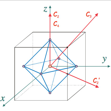
We change our frame for the cube symmetries, our new frame is:
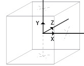
But this link is interesting just for the picture, the informations beside the picture are the achiral symmetry, we are dealing the chiral one. Thus the wikipedia article gives you all information, there is: 6 rotations by PI/2 8 rotations by 2*PI/3 3 rotations by PI about a 4-fold axis 6 rotations by PI about a 2-fold axis and the identity (it's the no-transformation) The axis are gave by the picture: The axis C4 and C2 are centered in the middle of cube's faces: the axis X,Y and Z: rotation about X-axis of PI/2 rotation about X-axis of PI rotation about X-axis of 3PI/2 (or about -X-axis of PI/2) Idem for Y and Z. Thus we found the 6 rotations of PI/2 and the 3 of PI. The axis C2' is centered on the middle of the edge and we need to apply a PI rotation to conserve the cube. We also can easily see that if we perform a rotation of PI or -PI remain to the same, thus, the rotation of PI about the exactly opposite axis remains also to the same. Thus there's only one transformation for 2 edges: rotation about XY axis of PI rotation about -XY axis of PI rotation about XZ axis of PI rotation about -XZ axis of PI rotation about YZ axis of PI rotation about -YZ axis of PI There are the 6 rotation of PI Finally the 8 rotation about C3. C3 is centered on the cube's vertices, thus there is 8 rotations of 2*PI/3 (for the chiral symmetry). rotation about XYZ axis of 2PI/3 rotation about -XYZ axis of 2PI/3 rotation about X(-Y)Z axis of 2PI/3 rotation about XY(-Z) axis of 2PI/3 rotation about (-X)(-Y)Z axis of 2PI/3 rotation about (-X)Y(-Z) axis of 2PI/3 rotation about X(-Y)(-Z) axis of 2PI/3 rotation about (-X)(-Y)(-Z) axis of 2PI/3 We finally found all the 24 elements of the octahedral symmetry (don't forget the identity). Now need to perform these rotations. If you don't yet know, quaternions are definitely the best way to perform rotation in 3D.
2.1.1.ii - Quaternion
Here is a short brief on quaternion. A quaternion is a kind of expansion of complex number, typically a quaternion has the form q = n+i*a+j*b+k*c, with i^2 = j ^2 = k^2 = -1. Usually we write a quaternion as a scalar number and a vector: q = (n , V = (a,b,c)) In this notation to rotate a vector U around the axis V with and angle of PI for example, the formula is: q = (cos(PI/2) , sin(PI/2)*V) U' = qUq* With q* the conjugate of q: q = (n, V) => q* = (n , -V) To do this operation you need to know how to do the product of quaternion and vector and two quaternion. For 2 quaternions here is the formula (Wikipedia), where qs is the scalar part and qv the vector part: For the vector-quaternion multiplication, you can set the vector as a quaternion with a scalar part equal to 0, and then use the same formula. At this point we learned everything we need to implement the table generation. 2.1.2 - The implementation Firstly we have to create some array with the real position of cube's vertices and center of edges: float vertexLocation[8][3] = {{-1.0f , -1.0f , -1.0f} , { 1.0f , -1.0f , -1.0f} , { 1.0f , -1.0f , 1.0f} , {-1.0f , -1.0f , 1.0f} ,
{-1.0f , 1.0f , -1.0f} , { 1.0f , 1.0f , -1.0f} , { 1.0f , 1.0f , 1.0f} , {-1.0f , 1.0f , 1.0f} };
float edgeLocation[12][3] ={
{ 0.0f , -1.0f , -1.0f} , { 1.0f , -1.0f , 0.0f} , { 0.0f , -1.0f , 1.0f } , {-1.0f , -1.0f , 0.0f },
{-1.0f , 0.0f , -1.0f} , { 1.0f , 0.0f ,-1.0f } , {1.0f , 0.0f , 1.0f } , {-1.0f , 0.0f , 1.0f},
{ 0.0f , 1.0f , -1.0f} , { 1.0f , 1.0f , 0.0f} , { 0.0f , 1.0f , 1.0f } , {-1.0f , 1.0f , 0.0f }}; The coordinates are in the cube center frame, to be able to perform the rotation without translation of the cube. And the list of symmetries: (in C++ I defined the operator * + - and ^ for the vector and quaternion, ^ for the cross product, and * for the scalar product between to vectors , here is the definitions of operators ) // Identity Quaternion id = rotationQuaternion(0, makeVector(1, 0, 0)); // Face centered rotation Quaternion rx = rotationQuaternion(M_PI/2 , makeVector(1, 0, 0)); Quaternion rx2 = rotationQuaternion(M_PI , makeVector(1, 0, 0)); Quaternion rx3 = rotationQuaternion(3*M_PI/2, makeVector(1, 0, 0)); Quaternion ry = rotationQuaternion(M_PI/2 , makeVector(0, 1, 0)); Quaternion ry2 = rotationQuaternion(M_PI , makeVector(0, 1, 0)); Quaternion ry3 = rotationQuaternion(3*M_PI/2, makeVector(0, 1, 0)); Quaternion rz = rotationQuaternion(M_PI/2 , makeVector(0, 0, 1)); Quaternion rz2 = rotationQuaternion(M_PI , makeVector(0, 0, 1)); Quaternion rz3 = rotationQuaternion(3*M_PI/2, makeVector(0, 0, 1)); // C3 - Diagonnal rotation Quaternion d1 = rotationQuaternion(2*M_PI/3 , 1.0f/sqrt(3) * makeVector(1, 1, 1)); Quaternion d2 = rotationQuaternion(-2*M_PI/3, 1.0f/sqrt(3) * makeVector(1, 1, 1)); Quaternion d3 = rotationQuaternion(2*M_PI/3 , 1.0f/sqrt(3) * makeVector(-1, 1, 1)); Quaternion d4 = rotationQuaternion(-2*M_PI/3, 1.0f/sqrt(3) * makeVector(-1, 1, 1)); Quaternion d5 = rotationQuaternion(2*M_PI/3 , 1.0f/sqrt(3) * makeVector(-1, 1, -1)); Quaternion d6 = rotationQuaternion(-2*M_PI/3, 1.0f/sqrt(3) * makeVector(-1, 1, -1)); Quaternion d7 = rotationQuaternion(2*M_PI/3 , 1.0f/sqrt(3) * makeVector(1, 1, -1)); Quaternion d8 = rotationQuaternion(-2*M_PI/3, 1.0f/sqrt(3) * makeVector(1, 1, -1)); // C2 - Edge centered rotation Quaternion e1 = rotationQuaternion(M_PI , 1.0f/sqrt(2) * makeVector( 1, 0, -1)); Quaternion e2 = rotationQuaternion(M_PI , 1.0f/sqrt(2) * makeVector( 1, 0, 1)); Quaternion e3 = rotationQuaternion(M_PI , 1.0f/sqrt(2) * makeVector(-1, 1, 0)); Quaternion e4 = rotationQuaternion(M_PI , 1.0f/sqrt(2) * makeVector( 0, 1, 1)); Quaternion e5 = rotationQuaternion(M_PI , 1.0f/sqrt(2) * makeVector( 1, 1, 0)); Quaternion e6 = rotationQuaternion(M_PI , 1.0f/sqrt(2) * makeVector( 0, 1, -1)); Quaternion symmetries[24] = {id , rx , rx2 , rx3 , ry , ry2 , ry3 , rz , rz2 , rz3 , d1, d2 , d3 , d4 , d5 , d6 , d7 , d8, e1, e2 , e3 , e4 , e5 , e6 }; With rotationQuaternion(float angle, Vector v) a function returning a quaternion q = (cos(angle/2) , sin(angle/2)*V) We need to take one second to think how the algorithm will proceed. There is 2 things to take in account: Firstly for certain configuration apply all the transformation will produce several times the same configuration. For example if we look a the 6th elementary configuration, performing a rotation around the Y-axis will not change the result. It's the same thing for the first configuration, you can perform all the rotations of the octahedron group, the result is always the same. So we have to check after a transformation, if the new cube configuration was not generated by another transformation. Secondly, if we take the example of the second elementary configuration, there is just the first vertex inside. But imagine all the others vertex are inside and the first is outside, then the configuration will be exactly the same. Thus after one transformation we have to check also the inverse cube configuration, and add it if it does not already exist. -For all elementary configuration -For all rotation -rotate the current configuration -rotate the edge's vertex of the configuration -for each rotated edge's vertex -find the corresponding edge's vertex code -compute the new configuration number -check if this new configuration number was not generated by another transformation -if not -write the list of edge's vertex code in the array of all configuration -check if the inverse of new configuration number was not generated by another transformation -if not -write the list of edge's vertex code in the array of all configuration -Write all the configuration in the array I think, all the problems of this implementation are solved, we just have to write the code. Here is the source code. (Hint: at the end of the program, display the number of generated configuration, it will give you a verification about your generation) The resulting table must be something like that: machingCubeTriangleTable (if you chose the same indexes as me you must have exactly the same thing). I add -1 at the end to have exactly the same size for all configuration and know when to stop. 2.2 - Use it Once we have the table of triangle vertices code, we just need to compute the cube configuration number between 0 and 255 (included), and it will correspond to one vertex list in the triangle list, just read the list in this way: for(int tr=0 ; triangleVertexTable[cubeIndex][tr] != -1 ; tr+=3) { surface.addTriangle(Triangle(Vertex(x+edgeVertex[triangleVertexTable[cubeIndex][tr]].x, y+edgeVertex[triangleVertexTable[cubeIndex][tr]].y, z+edgeVertex[triangleVertexTable[cubeIndex][tr]].z), Vertex(x+edgeVertex[triangleVertexTable[cubeIndex][tr+1]].x, y+edgeVertex[triangleVertexTable[cubeIndex][tr+1]].y, z+edgeVertex[triangleVertexTable[cubeIndex][tr+1]].z), Vertex(x+edgeVertex[triangleVertexTable[cubeIndex][tr+2]].x, y+edgeVertex[triangleVertexTable[cubeIndex][tr+2]].y, z+edgeVertex[triangleVertexTable[cubeIndex][tr+2]].z))); } If you display the shape at this point, you probably be disappointed by the result. You will obtain something like that.
This is due to the cubicle scan. But hopefully there is one very simple way to improve the result without a increasing the accuracy of the algorithm. 2.3 Improve the result with the interpolation Above all we have to figure out what is the problem. We said 'If there is one cube's vertex inside and one outside, then there is an edge's vertex at the middle of the edge'. This is not very clever, because we don't take the shape into consideration in this way. There's one picture to illustrate the problem in 2d. Both cases have the same cube configuration but they're definitly not the same.
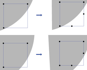
Instead of a binary function isVertexInShape() , we can make a scalar function. Imagine a scalar field of temperature, an isoline is a line going through all the points of the same temperature, or a isoline in a height field is point at the same height, like in this picture. We can do the same thing, we just have to turn our binary field into a scalar field. For example for a ball, we can return the distance to the center. And consider that the vertex is inside if this distance is lower than the isolevel. The isolevel is the level of the shape in the scalar field, as the isoline is the height in a height field. Thus with interpolation of the value of the boundary vertices of an edge we can deduce the right position of the edge's vertex: If for one edge between vertices A and B, the scalar field return va and vb, then: c= (va-isolevel) / (va-vb); newEdgeVertex = c*(B-A)+A //+FrameOrigin // You just have to test if with the edge configuration number if the shape cross the edge for this configuration, if yes then compute the vertex location with the interpolation, stock it, and when the program read triangle list, instead of searching the position into the classic edgeVertex array, search it in the new array you created. If you did it properly, you will obtain a smoother shape.
0 notes
Text
Marching Cube Algorithm - A complete implementation explanation - Part 1
1.1 - Find the cube configuration 1.1.1 - First try Before further explanations, we need to label the vertices of the cube, like in the following picture:
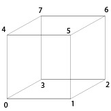
This labeling corresponds to indexes. And for the edges:
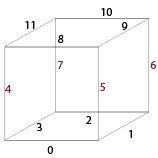
Finally we have to define a frame, I chose the bottom-left, but you're free to choose you're favorite one.
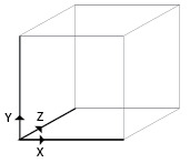
Inside the space scan, we analyze the cube's corners state (inside or outside of the shape). The set of corner's state define one configuration. For example one configuration could be: {corner 0 : inside, corner 1 : inside , corner 2: outside … } In fact there's 256 cube configurations, but only 15 of them are really different. With rotation and symmetries on the 15 elementary configurations we can produce all the 256 configuration.
The 15 elementary states are: (Wikipedia source)
Our first goal is to find which one of the 256 configuration our cube is in. "Very easy!" you gonna say: we just have to perform one action like that for all corner int vertexState[8] = {0}; vertexState[0] = isVertexInShape(Vertex0); vertexState[1] = isVertexInShape(Vertex1); ... With isVertexInShape() the method that check if one vertex is inside or outside and return something different of 0 if it is inside, 0 otherwise.
1.1.2 - Use bitwise operations to improve it But we can condense the int array into just one integer. Since we use binary states to define the vertices we can represent them into just one bit. 0 for outside, 1 for inside. If you don't know how the integer are computed, here is a little example: Binary code : 01001 (We read it from the left to the right) The corresponding integer is: 0*2^0 + 1 * 2^1 + 0*2^2 + 0*2^3 + 1*2^4 = 0*1 + 1*2 + 0* 4 + 0*8 + 1*16 = 18 This integer can only take values form 0 to 31. But the 'int' have a much taller range (4 or 8 bytes). Thus we can stock the binary states of corners into the first 8 bits of an integer. To do it properly, we use the corner's index notation previously showed up. The state of corner 'n' is stocked into the bit 2^n. But how to change just one bit of an integer ? Answer: the bitwise OR ('|') It's like the logic OR but just for bits: if p = 0011 and q = 0101 then p|q = 0111 (This is the truth table)
Here is the binary representation of vertex indexes:
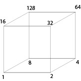
Let cubeConfig be the integer that represents the cube's configuration, for the corner 'n' it gives: if(isVertexInShape(VertexN) cubeConfig = cubeConfig | 2^n Instead of repeating this code 8 times for all cube's vertices, I wrote a list of 8 vertices in the right order, and made a loop on this condition. At this point we've got one number that describe the current cube's state.
1.2 - Find the triangles vertices
Since we know the configuration of corners we can deduce the edge configuration: for example if corner 0 is inside and corner 1 is outside, it means that the shape's surface cross the cube's edge and then there is a vertex of the shape at the middle of the edge. Thus every time corner0 = 1 and corner1 = 0 or corner0 = 1 and corner1=0 there is a vertex.
1.2.1 - Generate the table of edge configuration
Consequently we can create a map between each configuration of vertices and the configurations of edges. We just saw that the states of vertex0 and vertex1 create the state of edge0. Once we know the map between each couple of vertices and the edges we can create a table binding one of the 256 vertices configurations to one edges configuration, and thus knowing all the triangles vertices. To define the edge configuration we use the same trick, we stock each edge state in one bit. For a cube there is 12 edges:
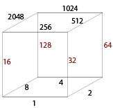
(Remind: we can know if one vertex if IN or OUT with the configuration number (cubeConfig) by using the bitwise AND: for the vertex4 the corresponding bit is 2^4 = 16 thus 'cubeConfig & 16' gives us only the state of vertex4) The algorithm to construct the table is quite simple. Let's call the map 'edgeToVertex', it binds one edge to a couple of vertices for(cubeConfig = 0 ; cubeConfig<256 ; cubeConfig++) { int edgeConfig = 0; for(int edge = 0 ; edge<12 ; edge++){ if( cubeConfig & edgeToVertex[edge][0] XOR cubeConfig & edgeToVertex[edge][1]) edgeConfig = edgeConfig | 2^edge; } print("%x ,",edgeConfig); } We use the same trick as for the configuration number, we stock the value of the state (0 or 1) in one bit. The best way make a small program to print the edgeConfig, and add the static table to our algorithm. This table only depends on the choice of labeling the vertices and edges. The result is: (with hexadecimal representation) int edgeConfig[256] = { 0x0 , 0x19 , 0x23 , 0x3a , 0x46 , 0x5f , 0x65 , 0x7c , 0x8c , 0x95 , 0xaf , 0xb6 , 0xca , 0xd3 , 0xe9 , 0xf0 , 0x910, 0x909, 0x933, 0x92a, 0x956, 0x94f, 0x975, 0x96c, 0x99c, 0x985, 0x9bf, 0x9a6, 0x9da, 0x9c3, 0x9f9, 0x9e0, 0x320, 0x339, 0x303, 0x31a, 0x366, 0x37f, 0x345, 0x35c, 0x3ac, 0x3b5, 0x38f, 0x396, 0x3ea, 0x3f3, 0x3c9, 0x3d0, 0xa30, 0xa29, 0xa13, 0xa0a, 0xa76, 0xa6f, 0xa55, 0xa4c, 0xabc, 0xaa5, 0xa9f, 0xa86, 0xafa, 0xae3, 0xad9, 0xac0, 0x640, 0x659, 0x663, 0x67a, 0x606, 0x61f, 0x625, 0x63c, 0x6cc, 0x6d5, 0x6ef, 0x6f6, 0x68a, 0x693, 0x6a9, 0x6b0, 0xf50, 0xf49, 0xf73, 0xf6a, 0xf16, 0xf0f, 0xf35, 0xf2c, 0xfdc, 0xfc5, 0xfff, 0xfe6, 0xf9a, 0xf83, 0xfb9, 0xfa0, 0x560, 0x579, 0x543, 0x55a, 0x526, 0x53f, 0x505, 0x51c, 0x5ec, 0x5f5, 0x5cf, 0x5d6, 0x5aa, 0x5b3, 0x589, 0x590, 0xc70, 0xc69, 0xc53, 0xc4a, 0xc36, 0xc2f, 0xc15, 0xc0c, 0xcfc, 0xce5, 0xcdf, 0xcc6, 0xcba, 0xca3, 0xc99, 0xc80, 0xc80, 0xc99, 0xca3, 0xcba, 0xcc6, 0xcdf, 0xce5, 0xcfc, 0xc0c, 0xc15, 0xc2f, 0xc36, 0xc4a, 0xc53, 0xc69, 0xc70, 0x590, 0x589, 0x5b3, 0x5aa, 0x5d6, 0x5cf, 0x5f5, 0x5ec, 0x51c, 0x505, 0x53f, 0x526, 0x55a, 0x543, 0x579, 0x560, 0xfa0, 0xfb9, 0xf83, 0xf9a, 0xfe6, 0xfff, 0xfc5, 0xfdc, 0xf2c, 0xf35, 0xf0f, 0xf16, 0xf6a, 0xf73, 0xf49, 0xf50, 0x6b0, 0x6a9, 0x693, 0x68a, 0x6f6, 0x6ef, 0x6d5, 0x6cc, 0x63c, 0x625, 0x61f, 0x606, 0x67a, 0x663, 0x659, 0x640, 0xac0, 0xad9, 0xae3, 0xafa, 0xa86, 0xa9f, 0xaa5, 0xabc, 0xa4c, 0xa55, 0xa6f, 0xa76, 0xa0a, 0xa13, 0xa29, 0xa30, 0x3d0, 0x3c9, 0x3f3, 0x3ea, 0x396, 0x38f, 0x3b5, 0x3ac, 0x35c, 0x345, 0x37f, 0x366, 0x31a, 0x303, 0x339, 0x320, 0x9e0, 0x9f9, 0x9c3, 0x9da, 0x9a6, 0x9bf, 0x985, 0x99c, 0x96c, 0x975, 0x94f, 0x956, 0x92a, 0x933, 0x909, 0x910, 0xf0 , 0xe9 , 0xd3 , 0xca , 0xb6 , 0xaf , 0x95 , 0x8c , 0x7c , 0x65 , 0x5f , 0x46 , 0x3a , 0x23 , 0x19 , 0x0 };
1.2.2 - Use it From now, every time we've got some configuration number (cubeConfig) we can directly find the edges configuration: 'currentEdgeConfig = edgeConfig[cubeConfig]'. Now we perfectly know where are the triangles vertices. But we need to construct the triangles in the right order and create the normals. At this point we can display all the vertices as simple points to check if the algorithm does work. With OpenGL the rendering is something like that: int currentEdgeConfig = edgeConfig[cubeConfig]; if(!currentEdgeConfig) continue; glPushMatrix(); glBegin(GL_POINTS); //For each edges for (int i=0; i<12; i++) { if(currentEdgeConfig & (int) pow(2,i)){ glVertex3f(x+edgeVertex[i].x , y+edgeVertex[i].y, z+edgeVertex[i].z); } } glEnd(); glPopMatrix(); Don't forget to avoid the rendering of fully inside or outside cubes (since we want to create only the surface of the solid). The fully inside state is cubeConfig = 255 and outside cubeConfig = 0, both have an edgeConfig = 0x0 (they're the first and last element of the edgeConfig table). At this point we've finished the first part of the tutorial, we rendered the shape with points.
0 notes


