#tin coated copper wires
Explore tagged Tumblr posts
Text
Tin coated copper wire has become increasingly popular in modern industries due to its unique properties and advantages over other wire coatings. This type of wire is made by coating copper wire with a layer of tin, which provides enhanced conductivity, corrosion resistance, and solderability.
0 notes
Text
Ashes rain upon your scalded palms pt 2
Prev | Chapter 2/3 | next | or read on AO3
Word Count 3571
Complete Wordcount: 9655
Maddie builds a Thing and finally seeks out the Ghost to get some answers. She had to find Danny. She had to save her son. The Ghost was her best lead, and if she had to face it, armed with nothing more than her determination, she would.
Contains: Maddie & Danny, Post apocalyptic vibes, and the usual bucket full of angst! @phicphight submission
------
Chapter Two
Before she could save anyone, Maddie needed to be more prepared than she was. Fenton Works was very much out of the question, since the only part of it still standing was the leftovers of the Portal. Scavenging from it felt like a bad idea.
But, there should be some workshops around that would carry the necessary equipment to build a very rudimentary shield or device. Jack's ancestors had a lot of know-how on how to contain evil spirits without high tech. Maddie had used their papers in a lot of her research and was pretty confident that she would be able to build something from what she would find lying around.
Danny had been an apprentice at a copper smithy, and she was fairly certain she still knew the layout of the workshop from when he had shown her around.
Mind made up, Maddie grabbed whatever she found promising in her current location. Which included the vacuum. That was some of the most advanced technology she would find in an average household, and if Jack’s ancestors got this far by just relying on analogue mechanics and plants, she could definitely do even better with some cutting edge tech. She also found a jar of salt that would help as a rudimentary protection against ghosts.
The radio she found was a bit too bulky to carry around, so she hoped that the workshop had one.
Her walk through the outskirts of the ruined townscapes felt eerie, she didn’t quite feel the same gooseflesh inducing sensation as she had closer to the portal, but she felt on edge in a way that felt purely instinctual.
The copper workshop was easy to break into since it decidedly lacked one of its walls. Maddie had hoped to escape the heat some more, but to get to the coppery, she had to get back into the zone of destruction, which meant that the buildings wouldn’t be intact anymore.
Still she was lucky. The workshop was mostly in one piece. Ash still coated everything, but she could still see that only some parts of the main room had really caved in.
So she started to rummage and explore.
Fairly quickly she had gathered a generator and fuel, enough copper and tin to build almost anything, tools to cut and bend, and wires and components from the vacuum. She even did find a radio that was in just as bad a state as the rest of the technology she had found so far, but still, it was a welcome addition to her arsenal.
The best thing was the soldering station though. In less time than she could have hoped for otherwise, she managed to build a construct that, in theory, should act like some kind of vacuum.
She didn’t have a container for the spirit she was hoping to catch, so she would need to watch out to keep the generator up and running.
As long as it did, the suction of the device would keep the ghost from going anywhere. It was a risk though. Even the generator itself was about to just fall apart, and her fuel supply was a joke at best.
She still needed a weapon. That was the conclusion she arrived at when she looked at the somewhat misshapen pile of wires and plates that were soldered together sloppily. To think she was going to bet her life on a device that was maybe as big as a dinner plate, that was untested and unheard of…..
A glance at the sky made her stomach sink. It was hard to tell with the diffused lighting, but slowly and steadily the sun had made its way across the sky. It was August, so days were fairly long, but she maybe had two more hours before dusk. Once it got dark, she’d be even more defenseless. Running would already be difficult enough with all the rubble, but in the dark? When ghosts were the most active too?
Maddie turned around and tried to find something that would work as a weapon.
There were the workbenches and the cupboards and the drawers with tools. She opened them haphazardly but nothing really stood out. She did manage to find a knife, and there was the salt she had pilfered from the house earlier, so she might be able to at least coat the blade and hope the theories were sound.
While she looked for another, better, alternative, her eyes fell on something she had dismissed as another pile of broken equipment.
She drew closer though, on her search, and noticed that the misshapen lump was a tarp over something.
Her hands moved carefully and she held her breath when removing the tarp shook up a cloud of ash and dust.
It took a moment to clear, but when it did, Maddie let out a shuddering exhale. Before her was a half finished telescope. It showed off craftsmanship and passion even in its half finished state. And it would never be finished. It would never be used to look at a night sky.
This was Danny’s.
There was paper under the parts. Plans and schematics, and more than a few drawings of constellations, that Danny would surely have gotten into trouble for, to be writing them on the margins of his work as just an apprentice.
Maddie couldn’t help the anger that flashed unbidden. She would fix this. Danny would get to see the stars through his telescope. She was going to find him and then bring him back somehow. They would find a way, and then Danny would finish his telescope and she would finish the portal and make sure nothing like this future would ever happen. She would eradicate every ghost beyond existence before letting them use her portal as a bomb.
“Focus on the tasks at hand, Maddie,” she told herself. She had her ghost trapping device, and she had a knife that she could coat in salt.
Next would be finding said ghost, and getting answers.
She nodded to herself and began pulling the tarp back over Danny’s unfinished telescope. It felt strangely mournful, but fitting in a way. She just didn’t like this association with her son. He had to be alright.
Maddie couldn’t stay here any longer. Time was of essence.
Quickly she found another tarp, folded up half heartedly on another shelf, and began gathering her makeshift machinery in it. She’d have to sling it over her shoulder so she would have her hands free to carry around the generator. She cursed internally that there was nothing like a battery that would both fuel an invention like that, and survive 100 years in an apocalyptic oven.
It mattered none. She wanted to get out in the open. Ghosts would be at an advantage anyways, whether she was within four walls or an open field, but with their supposed ability to walk through walls, which she herself decidedly lacked, she didn’t want to encounter the energy where she could be cornered.
The ghost had been around the portal and some part of her, the one that would shudder when she thought about going back to the epicenter of it all, knew that they were connected. She would bet that the ghost was the one to blow up her portal in her future.
It still mainly counted as a guess, but it was the only lead she got, so there was that.
She looped the tarp around her torso and made sure it would hold the delicate machine. Her handkerchief was back over her mouth and tied behind her head. The knife was in her belt and just one motion away.
So with a grunt she hefted the generator on her shoulder and began to move back out into the open.
Even just after a few meters, every step was already a struggle, and in no time she felt sweat run down her back.
One foot in front of the other.
Breathe in hot air, exhale hot air.
Find Danny. Save him.
Find Danny. Save him.
Find Danny. Save Him.
The mission became Maddie’s mantra throughout the trip and no matter how much her legs shook, she didn’t stop until she could make out her portal's shadowy silhouette again.
Heat flared up and gooseflesh rose on her arm. Not yet to the same extent as it had back then, when she saw the ghost. But she knew it must be close. She could even feel its eyes on her. That, or her mind had decided to give in to the heat.
But it proved her right. She hadn’t been certain before, but now she would dare say, the ghost wouldn’t come find her without an added incentive. She had made quite some noise back in the coppery, and had almost expected to be discovered. So if it didn’t seek her out itself, she had to come to him.
The problem just now presented: setting up would take some time.
The closer to the portal she got, the longer she’d had to endure the heat, which already felt more than she could handle for long, and the more likely it would be that the Ghost would actually engage her before she was done.
She put down the generator with a resounding thud. Her legs almost gave out. Maybe she didn’t have that much room for choice anyways, it felt impossible to lift the generator back up again.
At least she was at a relatively flat part of the whole mayhem.
It would have to do.
Maddie began setting up her invention in silence. It was unnerving. The heat and exhaustion were making her hands shake and more than once she almost broke something off.
The sun was now definitely reaching towards the horizon too, so she felt compelled to hurry. To rush.
The threat of being stranded here at night sat in the back of her mind- she felt uncomfortable to even take a moment to double check if everything was connected properly before turning on the generator.
The disc shaped machine sat in place though. No wire disconnected and all parts undamaged from her trip ups during the walk.
There wasn’t a lot of fuel, so she had to make it count. Meaning, she had to get the ghost to come to her, before turning it on. Otherwise it might run for minutes or hours that she couldn’t spare.
She could still feel the ghost. The hair on the back of her neck, that refused to lie flat. It was somewhere around here. And just because she couldn’t see it, didn’t mean that it couldn’t be watching her this very moment.
Her running hypothesis was that the ghost had, for some reason, destroyed her portal to use it as a bomb. So, assuming it didn’t know all that much about tech, she could bluff her way through this.
Her mouth felt dry. Find Danny. Save him. She had to do this. For her son.
She kept her hand over the switch of the generator. For her son.
Deep inhale and hope her voice would hold after a day of impure air. For her son.
Showtime.
“VILE SPECTER! YOU MAY HAVE CLAIMED THE FENTON PORTAL, BUT YOU SHALL NEVER HAVE MINE. I WILL TEAR THROUGH THE VEI-”
Green.
Her vision was filled with the sight of a pair of glowing green eyes inches away from her own. She flipped the switch and for a terrifying moment she couldn’t breathe. She was in a furnace and any inhale would surely burn her lungs. Instincts screamed at her to runrunrun get away!
But her SON. Her SON needed her. She stood her ground even as teeth were bared and a growl made the very air oscillate.
A maw filled with razors opened so close she could feel its hot breath on her throat. Black smoke coiled around her like bindings.
Then the generator hummed and she could only sink to the floor with her entire being shaken, while the ghost thrashed and spat in fury at the sudden interruption of its meal..
The Disk was doing its job. It sucked the ghost towards it, like on a retractable leash. It had a bit of a radius it could struggle against, one that Maddie had to stay conscious of, but it couldn’t get away. It was confined, even if it hadn’t sunk in for the creature yet.
It screeched furiously and Maddie wondered suddenly if it was even capable of human speech. It had to. If it didn’t, her whole plan was about to fall apart.
For now, she could get back into her composed self. She was deeply shaken, the ghost had appeared out of nowhere. From one moment to the other it just had been there. Right in her face. It could have snapped her neck before she would have known what had happened.
Now she would be relatively safe. As long as the generator held.
The Scientist in her made her stop and observe for at least a moment. This still was quite groundbreaking, even under the circumstances, and who knew when the next time would be, that she could look at a ghost from such a short distance.
Now that she looked, she was fairly certain the ghost would be able to understand human speech after all. It only hissed and snarled right now, but it was fairly humanoid. It was built like a lanky teenager. Long limbs ended in clawed and blackened hands. Its body looked like it was covered in a black fabric that stretched over bony ribs and shoulders. The face was distorted in its fury, but while the features were humanoid enough, they were also somewhat otherworldly. Its white hair that was as long as it was tall, hid some of it, but she could still make out the most important bits. The eyes were a shade of green shed never seen before. Glowing and bright. The sclera was black though, which added to the strangeness of the green. Its bone structure looked rather delicate for a being this terrifying. Now that she looked closer, not much muscle could be seen either. Yet she had no doubt it would be able to overpower her with one hand.
Well, she would like some answers before that became the case.
“Stop that.” she ordered with a hoarse voice. The ghost growled in response.
“Let me guess, it’s your first time being caught? Then let me tell you the rules. I ask you questions, you answer them. If you do, you will be let go, and will not learn what sort of inventions I'm keeping in my lab coat.”
It still snarled at her, but it had its eyes locked onto her now. It definitely understood, it just didn’t seem to agree. Maddie fought to suppress a shiver at the intensity of its glare.
“Why did you destroy the Portal.”
More posturing was what she expected, but it actually froze for but a moment. Not for long though. It found renewed energy to throw itself against its incorporeal restraints.
“Hah!” she scoffed, “So I was right! You are the one responsible!” Maddie hissed herself. It didn’t take a verbal reply to get answers. Its behavior was clear enough.
“So you just decided to do all this?” she gestured around the wasteland, acutely noting the rise in temperature. “You somehow blew up the portal, about a century ago, to do what? Was this your goal? To turn a whole city into a hellscape?” Her voice rose and for the first time the creature seemed to not just want to get out of its cage, but away from her specifically.
"Answer me!” She yelled and the ghost all but flinched.
"Why did you do all this?!” Maddie’s fists shook as she held them pressed to her side. She wanted to kick and bite and tear apart. But this thing. She wouldn’t stand a chance. It made her sick.
The ghost didn’t reply.
“No matter." Maddie took a steadying breath. It was getting hard to really think. The air was thick and heavy. The temperatures have been steadily rising and her makeshift mask was soaked and starting to make it even harder to catch her breath.
“What I’m really here for is to find Danny. You have something to do with this, don’t you?!” She snarled not less viciously as the ghost had. “You’re the key to finding him, so I will not let you go, until you tell me where he is!”
“No.” That was the first thing she’d heard from the ghost that wasn’t just a sound. Its tone was disbelieving.
But then it said it again. And again. Anger rising and heat flaring. It’s body turned to smoke at the edges like it was getting singed.
“you know something!” She yelled in the face of that admittance. The ghost lashed its tail like an angered cat.
“Go away!” it screeched.
“Not until i have found Danny.” She screamed back. It was flying in circles, looking for a way out of its enclosure. It was furious, Maddie could tell, but so was she.
“What did you do to him? Whatever it is, he didn’t deserve it. He is kind. He is bright. And he deserved nothing you could do to him.”
It turned to her and bared its fangs once more. “Oh, you didn’t like that, huh? Cant handle the truth that you are none of those things?” Maddie grit out.
“How would you even know?!” The ghost roared in fury and Maddie couldn’t take the heat anymore. She needed more air. She tore off her makeshift mask and gasped.
“How couldn't I know,” she breathed into the unexpected silence " when I’m his mother.”
The air that had been charged with tension until then, suddenly imploded.
“No,” it began to mumble again, “No, this cannot be.”
“I killed you.” it confessed, and Maddie had expected as much. What she wasn’t expecting was the shift in mood. Where before there had been anger, now there was despair. The sky darkened and flakes of ash started to fall like a sick mimicry of snow.
“So you did. And if you have any morsel of humanity left, you will give me back Danny.” Her voice was firm in the face of its dismay.
“I killed you.” It repeated again.
She was about to snap.
“I killed everyone.” it whispered and the expression on its face distorted to one of pure anguish as it clutched its chest.
Wind, something that had been absent since her arrival, picked up and whipped her hair around. Ash stung her eyes and exposed skin and she had to brace against the gusts of hot air.
The ghost started to rock back and forth with wide unseeing eyes.
“I killed them. I killed everyone. I-” Maddie reached for her knife nervously.
Its head snapped up and-
crack.
A noise that was akin to a clap of thunder suddenly originated from the ghost and everything stopped.
The temperature too, cut like hot metal being plunged into water.
But Maddie barely even recognized it, when following the cracking sound, the ghost dropped the rest of the way to the ground like gravity had suddenly been turned back on and a ring of blinding light sprung forth from the center of its- his chest.
It took barely a moment, but something had fractured and the ghost, like a broken illusion, got replaced with a human.
He looked up and Maddie dropped her knife. Framed by black hair that pooled on the ground, her son's face, his eyes stared at her with an expression of utter grief and despair.
“I know that Danny isn’t any of those things, because I am Danny.” There was none of the echo anymore.
But this- surely this was a lie-
“But I killed them. I killed everyone I ever cared about. Everyone is dead. They are all dead. It’s all my fault, If i hadn’t- I had to bury you. I killed you. I killed my own mother, my own family. I’m a monster. I-” in agony he doubled over and Maddie scrambled up to rush to her son. This was wrong. This had to be a mistake. She had to find Danny. (He’s here.) She had to save him! (he was already gone.)
Her hands hovered over his thin shoulders.
“Danny-” The boy in front of her, didn’t even hear her. He curled up, and a scream built. The sheer desolation was palpable. Then the scream grew in intensity, it got hard to breathe again, she clasped her hands over her ears but it pierced right through, until it became a wail and Maddie knew nothing but her son's agony as if it was her own.
The image of him kneeling on the ground next to her, his forehead pressed into the ash would probably be the last thing she would see. It made her heart break almost as audibly as whatever had broken in her son.
She knew whatever was happening would mean an End, and after a century, maybe that was what he needed. She embraced him then, even as her eardrums ruptured and her lungs burst. Maddie had found him. If only she could have saved him too.
At least she would hold him, until this ashen world of gray, finally turned to black.
“Time out.”
#phic phight 2024#phan phic#phic phight#phic phight 24#fanfic#ao3#dp#danny phantom#phandom#mywriting#originalwork#mydannyphantom
16 notes
·
View notes
Text
#FishFriday:

Plate with Emblematic Pairs of Fish (mahi-ye maratib)
India, Uttar Pradesh, Awadh, Lucknow, c. 1880
Bidri-ware (zarbuland technique)
D: 6 3/4 in. (17.15 cm); H: 1/2 in. (1.27 cm)
LACMA M.2001.100
“The primary decoration on this bidri ware plate is a pair of fish arranged head-to-head with their curved bodies forming a circle. Known as the mahi-ye maratib (Fish of Dignity), it was an insignia of exalted rank that the Mughal emperors and earlier Middle Eastern rulers bestowed upon their subordinate chieftains in recognition of valorous military service. In 1720 it was awarded by the Mughal Emperor Muhammad Shah (r. 1719–48) to Saadat Khan, the Governor of Akbarabad (Agra), who soon became the Governor of Lucknow from 1722 to 1739. The fish emblem subsequently served as the dynastic leitmotif of the Lucknow court and was frequently displayed on its decorative arts and palatial architecture. It was represented in state processions as a fish and two gilt globes carried on a standard. A heraldic form consisting of a pair of honorific mermaids bearing a crown and flanking a shield was used as the personal coat of arms of King Wajid Ali Shah (r. 1847–56). Bidri ware is made from a predominately zinc-based alloy, along with smaller amounts of lead, copper, and/or tin. The ornamentation of bidri ware from the Deccan and eastern India typically features inlaid silver sheet or wire designs, which are rendered flush and burnished. Lucknow bidri ware is distinctive in that it is often executed in bold relief (zarbuland technique), in which the inlaid metals are allowed to remain protruding slightly above the surface and are then adorned with sheet overlay and incised motifs.”
#animals in art#19th century art#metalwork#animal emblems#fish#Fish Friday#Indian art#South Asian art#Asian art#colonial art#Bidri ware#LACMA#plate
9 notes
·
View notes
Text

Tinned Core Wiring
Ensure reliable electrical connections with high-quality tinned core wiring from LED Advantage. Designed specifically for marine, caravan, and automotive applications, this wire offers excellent corrosion resistance, making it ideal for harsh environments. The tin coating protects the copper core from oxidation and ensures long-lasting conductivity, even in moisture-prone conditions. Flexible, durable, and easy to work with, our tinned core wire is perfect for wiring projects where performance and longevity are essential. Available in various gauges and lengths, it suits a range of applications. Trust LED Advantage for dependable tinned core wire and keep your electrical systems running smoothly!
0 notes
Text

Best Copper Coated Wire Distributors for Your Needs
Ganpati Wires, a leading Copper Coated Wire Distributors, offers high-quality products designed to meet various industrial needs. With a focus on reliability and performance, their copper-coated wires are ideal for electrical, construction, and manufacturing applications. Visit Now @ https://www.ganpatiwires.com/bare-tin-coated-copper-wire.html/
0 notes
Text
Understanding Dual 2/0GA-1/0GA Reducers: A Comprehensive Guide
In the realm of electrical and power distribution systems, ensuring efficient and safe connections is paramount. One critical component that facilitates such connections is the wire reducer. Specifically, the Dual 2/0GA-1/0GA reducer plays a vital role in various heavy-duty applications. This article delves into the specifics of these reducers, exploring their functionality, applications, benefits, and considerations for use.
What is a Dual 2/0GA-1/0GA Reducer?
A Dual 2/0GA-1/0GA reducer is an electrical connector designed to join or transition between cables of different gauges—specifically from dual 2/0 gauge wires to a single 1/0 gauge wire or vice versa. The "GA" stands for American Wire Gauge (AWG), a standard measurement system for the diameter of electrical conductors. In this context:
2/0 Gauge (also known as 00 AWG): Refers to a thicker wire capable of carrying higher current loads.
1/0 Gauge (also known as 0 AWG): Slightly smaller in diameter compared to 2/0 gauge, suitable for slightly lower current capacities.
These reducers are essential in scenarios where there is a need to adapt or consolidate multiple heavy-duty conductors into a single pathway, ensuring continuity and reliability in power transmission.
Key Features and Design
Material Composition
Dual 2/0GA-1/0GA reducers are typically constructed from high-conductivity materials such as:
Copper: Known for its excellent electrical conductivity and durability. Copper reducers often feature a tin plating to resist corrosion.
Aluminum: Offers a lightweight and cost-effective alternative, though with slightly lower conductivity compared to copper. Aluminum reducers are also often coated to prevent oxidation.
The choice of material depends on the specific application requirements, environmental conditions, and budget considerations.
Construction and Design Aspects
Dual Entry Points: The design includes two entry points accommodating 2/0 gauge wires, allowing for the consolidation or branching of circuits.
Single Exit Point: The exit point accommodates a 1/0 gauge wire, facilitating a seamless transition in conductor size.
Secure Fastening Mechanisms: Equipped with set screws or compression fittings to ensure a tight and secure connection, minimizing resistance and preventing accidental disconnections.
Insulation and Protection: Some reducers come with insulating covers or are designed to be used with heat shrink tubing to provide additional protection against environmental factors and electrical shorts.
Applications of Dual 2/0GA-1/0GA Reducers
These reducers find widespread use across various industries and applications, including:
Automotive and Marine Industries
High-Performance Audio Systems: In vehicles and boats where powerful audio setups require robust wiring configurations, these reducers help manage and distribute power efficiently.
Battery Connections: Facilitating connections between multiple batteries or between batteries and heavy-duty equipment like winches and inverters.
Engine and Electrical Systems: Ensuring reliable connections within complex electrical systems that demand varying current capacities.
Industrial and Commercial Electrical Systems
Power Distribution Panels: Assisting in organizing and connecting multiple power feeds into centralized panels or sub-panels.
Heavy Machinery Wiring: Providing secure connections for machinery that requires substantial power input, ensuring minimal voltage drop and heat generation.
Renewable Energy Installations: In solar and wind power setups where consolidating power from multiple sources is necessary.
Construction and Infrastructure
Building Electrical Systems: Used in large-scale electrical installations within commercial buildings, hospitals, and data centers where robust and reliable power distribution is critical.
Emergency Power Systems: Facilitating connections in backup power systems, including generators and uninterruptible power supplies (UPS).
Benefits of Using Dual 2/0GA-1/0GA Reducers
Enhanced Electrical Efficiency
By providing a secure and low-resistance connection between conductors of different sizes, these reducers help maintain optimal electrical performance, reducing energy losses and preventing overheating.
Flexibility and Versatility
They offer flexibility in designing and modifying electrical systems, allowing for easy upgrades and expansions by accommodating different wire sizes and configurations.
Improved Safety
Proper use of these reducers ensures compliance with electrical standards and codes, reducing the risk of electrical faults, fires, and equipment damage.
Ease of Installation
Designed for straightforward installation, they save time and labor costs. Clear labeling and standardized sizes make selection and usage convenient for electricians and installers.
Considerations for Selecting and Using Reducers
Compatibility
Ensure that the reducer is compatible with the conductor materials being used (e.g., copper-to-copper connections). Mixing different metals can lead to galvanic corrosion over time.
Current Carrying Capacity
Select reducers that can handle the maximum expected current load to prevent overheating and ensure longevity.
Environmental Conditions
Consider the operating environment:
Corrosive Environments: Opt for reducers with appropriate coatings or made from corrosion-resistant materials.
Temperature Extremes: Ensure the materials and insulation can withstand the temperature ranges they will be exposed to.
Compliance with Standards
Choose products that meet relevant electrical codes and standards, such as UL (Underwriters Laboratories) listings, to ensure safety and reliability.
Installation Practices
Proper Tightening: Follow manufacturer specifications for torque settings on set screws to ensure secure connections without damaging the conductors.
Insulation: Use appropriate insulation methods to protect against electrical shorts and environmental damage.
Regular Inspection: Implement routine checks to identify and rectify any signs of wear, corrosion, or loosening.
Dual 2/0GA-1/0GA reducers are indispensable components in modern electrical systems, offering efficient and reliable solutions for connecting conductors of varying sizes. Their robust design and versatility make them suitable for a wide array of applications across different industries. By understanding their features, applications, and proper usage considerations, professionals can ensure optimal performance and safety in their electrical installations. Whether in automotive, industrial, or construction settings, these reducers play a critical role in maintaining the integrity and efficiency of power distribution networks.
0 notes
Text
Silver Nanowires: The Next Generation of Conducting Materials
Introduction to Silver nanofibers Silver nanofibers are extremely thin silver wires with diameters measuring only tens to hundreds of nanometers. At such a small scale, silver exhibits unusual optical, electrical and thermodynamic properties compared to bulk silver. Silver nanofibers have found use in applications requiring transparent conducting materials like touchscreens. Properties of Silver nanofibers Silver nanofibers conduct electricity exceptionally well due to the high electrical conductivity of bulk silver. The electrical resistivity of silver is only about 1.59×10⁻⁸ Ω·m, second only to copper. At the nanoscale, Silver nanofibers retain much of this high conductivity despite their small cross-sectional area. Additionally, long nanowires allow percolation or contact between nanowires to form conductive networks even at low surface coverage or mass fractions. This makes Silver nanofibers viable at transmitting electricity through transparent materials. Optical properties are also influenced at the nanoscale. Silver Nanowires is highly reflective in the visible spectrum as a bulk material. However, Silver nanofibers only weakly absorb and scatter visible light due to resonance effects dependent on nanowire diameter, reducing opacity. Transmission of visible light can exceed 90% with Silver nanofibers films only tens of nanometers thick. The nanowires also transmit infrared radiation well. These qualities give Silver nanofibers their useful optoelectronic properties. Producing High Quality Silver Nanowires Several techniques exist for producing high quality Silver nanofibers on an industrial scale. Polyol synthesis is a common method which uses ethylene glycol both as a reducing agent and reaction solvent. In this process, silver nitrate is reduced by ethylene glycol at elevated temperatures (150-200°C) in the presence of a structure-directing agent like polyvinylpyrrolidone (PVP). The PVP bonds preferentially to certain crystallographic faces of growing silver nanoparticles, directing their one-dimensional growth into nanowires. Reaction time, temperature, and concentration of reagents control the dimensions of synthesized nanowires, which are usually 50-200 nm in diameter and 5-100 μm in length. Post-synthesis processing like washing and drying yields pure Silver nanofibers powders. PVP-coated Silver nanofibers produced by polyol synthesis typically have good aspect ratios above 100 and acceptable electrical conductivities. However, surfactants and byproducts must be removed before application to avoid compromising transparency or conductivity. Additional techniques like electrospinning can also fabricate Silver nanofibers, enabling mass production. Overall, wet chemistry methods allow cost-effective synthesis of high quality Silver Nanowires nanofibers materials. Uses of Silver nanofibers in Devices Transparent Conductive Films One major application of Silver nanofibers is as a material for transparent conductive films (TCFs). TCFs require optical transparency as well as high electrical conductivity, which bulk metals cannot provide. Silver nanofibers combine these properties, transmitting over 90% of visible light while achieving conductivities within an order of magnitude of ITO. Silver nanowire TCFs have begun replacing indium tin oxide (ITO) in applications like touchscreens due to lowered costs and mechanical flexibility. At optimized surface densities, Silver nanofibers form a percolated conductive mesh that maintains excellent optical qualities even as electrical conductivity surpasses that of ITO. This makes them promising for next-generation touch-enabled displays and transparent electrodes. Organic Electronics and Solar Cells
Get more insights on Silver Nanowires
Vaagisha brings over three years of expertise as a content editor in the market research domain. Originally a creative writer, she discovered her passion for editing, combining her flair for writing with a meticulous eye for detail. Her ability to craft and refine compelling content makes her an invaluable asset in delivering polished and engaging write-ups.
(LinkedIn: https://www.linkedin.com/in/vaagisha-singh-8080b91)

0 notes
Text
100g roll of solder for guitar wiring
100g roll of solder for guitar wiring. Flux-cored solder wire (60% tin, 40% lead). FREE UK P&P Suitable for fast soldering on copper or brass surfaces and solder-coated materials. Ideal for use on micro electronics, fine wires and most other electrical and electronic soldering operations. External diameter 1mm. Product Features Flux-cored solder (60% tin, 40% lead) Suitable for fast soldering on…
0 notes
Text
Exploring the Versatility of Stranded Flexible Copper Jumpers and Silver-Plated Copper Wire
Introduction
Today's low-pressure technology relies heavily on electroplating materials. From the gadgets we use every day to the electricity infrastructure supplying electricity to cities, dependable electrical supplies are critical. Among these items, soft wires brass jumpers in silver-plated brass wires stand out for their adaptability and effectiveness.

What are Stranded Flexible Copper Jumpers?
Definition and Structure
Simple brass jumps are made from several small twisted copper wires, forming a simple single type. This design offers greater flexibility compared to rigid copper tubing, making it ideal for applications requiring movement or bending.
Applications and Uses
Stranded Flexible Tin Coated Copper Wire Rope jumps in wires are commonly used in electrical equipment, grounding systems, and bonding applications. Their flexibility makes them suitable for dynamic environments with vibration or frequent movement.
Advantages of Stranded Flexible Copper Jumpers
Flexibility and Durability
The main advantage of flexible copper jumpers is their flexibility. This quality reduces the risk of breakage when the lines are bent or twisted, and increases their durability.
Conductivity and Efficiency
Copper is known for its excellent conductivity, and stranded flexible copper jumpers maintain this characteristic while adding the benefit of flexibility. This provides a smooth flow of electricity with minimal energy loss.
Installation and Maintenance Easy
Easy Installation Process
Installation of stranded flexible copper jumpers is straightforward due to their flexibility. It can easily be moved around tight surfaces and around obstacles, making installation easy.
Maintenance Tips
Regular inspection is essential to ensure the longevity of the flexible brass jumpers. Check for evidence of wear and tear, and replace all damaged parts as quickly as you can to ensure peak performance.
What is Silver Plated Copper Wire?
Definition and Structure
Silver-plated copper wire is made of copper covered with a small amount of silver. This combination mixes copper's powerful durability and silver's above conductivity and oxidation resistance.
Applications and Uses
Silver-plated copper wire is used in repetitive and high-temperature applications, such as aerospace, telecommunications, and military equipment. The silver coating increases performance in these harsh environments.
Benefits of Silver-Plated Copper Wire
Enhanced Conductivity
Silver is the most conductive metal, and coating copper wire with silver increases the overall conductivity of water. This makes silver-plated copper wire ideal for repetitive applications where efficient signal transmission is critical.
Corrosion resistance
The silver coating protects the wire prevent corrosion and oxidation, enhancing its life in all kinds of events.
Stranded, flexible copper jumpers & silver-plated copper wire.
Key Comparison of Differences
While both types of wire are highly conductive, stranded flexible a copper jumpers offer greater flexibility, making them ideal for frequent flight applications. Silver-plated copper wire, on the other hand, performs well at elevated frequencies and temperatures because of its excellent conductivity & corrosion resistance.
When to Use Each
Use Stranded Flexible Copper Connectors jumpers in sticky areas where flexibility is required, such as mechanical or electrical outlets. Choose silver-plated copper wire in multi-use applications such as telecommunications and aerospace, where high conductivity and durability are required.
Typical Applications of This Material
Telecommunications
Flexible copper jumpers with both wires and silver-plated copper wire are important in the telecommunications industry. They ensure reliable signal transmission and power distribution, supporting the larger network.
Automotive Industry
Flexible horizontal copper leaps are used in cars electrical systems due to their flexibility & durability. Silver-plated wire made from copper is utilized in applications requiring strong conductivity and resilience in harsh conditions.
Aerospace Industries
Silver-plated copper wires have become commonplace in the aerospace sector due to their superior performance for high-frequency and high-temperature settings. This guarantees the safety & reliability of vital space systems.

Recycling Copper Jumpers and Silver-Plated Copper Wires
Emerging Technologies
Emerging technologies, such as electric cars and renewable energy sources, are increasingly dependent upon high-performance electrical components. Both smooth copper jumpers and silver-plated copper wire are crucial in these new applications.
Future Trends
As technology advances, the demand for efficient and durable electrical products will continue to grow. The versatility and reliability of the smooth copper jumpers and silver-plated copper wire position them well for future developments.
Environment and Sustainability
Recycling and Recycling
Copper and silver all highly recyclable materials. Recycling this metal reduces its environmental impact & conserves natural resources, pushing the business to adopt more sustainable methods.
Environmentally friendly practices
Manufacturers are using ecologically friendly processes to manufacture elastic copper jumpers & silver-plated copper wire. This includes removing waste, avoiding energy, and utilizing environmentally friendly products and procedures.
Choosing the Right Supplier
What to Look for in a Supplier
When choosing a supplier of smooth brass jumpers and silver-plated brass wire, consider factors such as product quality, reliability, and customer service. Ensure that the supplier has a good reputation and delivers products that meet industry standards.
Questions to Ask Potential Suppliers
What certifications do you have for your products?
Can you provide references from interested customers?
What is your quality management system?
How do you handle product verification and returns?
Cost Considerations
Price and Performance
While cost is an important factor, it is important to balance price and performance. Investing in a simple smooth brass jumper and silver-plated brass wire can provide long-term savings by reducing maintenance and replacement costs.
Long-Term Financing Investment
Think about the long-term advantages of using excellent in quality electrical equipment. High-quality items may cost more at first, but they boost performance, durability, and confidence, resulting in expense advantages.
Case Studies
Successful Applications
Several manufacturers have successfully used flexible copper jumpers and silver-plated copper tubing in their systems. This case study highlights the value of high-quality electrical components for a variety of applications.
Lessons Learned
Learning from the experiences of others can provide valuable insights into the best practices for flexible copper jumpers and silver-plated copper wire. This knowledge can help improve performance and efficiency in your applications.
Conclusion
Flexible copper jumpers with silver-plated wire made of copper are critical components of current electrical systems. Their flexibility, durability, and efficiency render them great for an array of applications across industries.
0 notes
Text
0 notes
Text
Comparing the Aesthetics of Different Metal Plating
Metal plating or metal finishing is a very useful technique used in a range of processes, whether decorative or industrial. Using the right metal finish can completely transform the look, feel and usability of the product. If you are looking to aesthetically improve a product, then understanding the different metal finished would be greatly helpful. One of the most common plating is silver plating in UAE because of its remarkable properties. There are other plating options too, check them out as well.
Need for metal plating
The metals ideally used in metal plating are: Gold, Silver, Tin, Copper, Chrome, Rhodium, Zinc, Zinc Nickel, Zinc Iron and Black Nickel. With the right metal plating option, it is possible to improve the product’s surface, increase corrosion resistance, improve paint adhesion, reduce friction, act as a shield against radiation and even change the conductivity of the material. Metal plating is also used in jewelry to improve their look, and make cheap jewelry alluring and attractive.
Gold Plating
Gold plating is often done on copper to provide a corrosion-resistant electrically conductive layer. Hence, it is used on electronic spare parts, mainly electrical connectors, printed circuit boards etc. This chemical process is also known as gold electroplating, and before doing it, the technician will ensure that the surface is clean with no dirt or oil on them. This is a great option because not only will it look good, but it will also prevent oxidation and thus no rusting.
Silver Plating
Silver Plating in UAE is also almost similar to Gold plating, and is thus excellent for electrical conductivity. Since it is a cost-effective option to gold, many people switch to silver to plate parts made from copper. Silver is beautiful and elegant, and gives off an excellent metal finish.
Tin Plating
Tin plating provides an even cheaper option when compared to gold, platinum, etc. This is used mainly for industrial works and is used in a variety of industries including electronics, jewelry making, aerospace, etc. You will also find tin plating solution in cans where food products are stored.
Rhodium plating
This is also used for plating jewelry because of its qualities like durability, aesthetics and light reflecting qualities. A thin coating on a piece of jewelry will work wonders.
Nickel plating
Nickel plating is quite often used for that lovely finish on plumbing and household appliances, furniture and supplies. You will find this used on wire racks because of its striking, mirror-like finish. It is also corrosion-resistant.
Silver plating in UAE is most often the commonly used plating metal because it is resistant to heat, and a number of common chemicals and acids. It does not oxidize or degrade, so used in high-temperature environments like the automotive industry. Engine manufacturers use silver instead of lubricants because of its remarkable temperature resistance. Silver is also often used as a base material before other kinds of plating is applied, especially matte coating.
For more details -
0 notes
Text
Review, teardown, and testing of RSP-320-24 Mean Well power supply
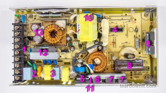
The RSP-320-24 is a 24-volt power supply with a maximum current of 13.4 amps. The supported mains voltage is from 100 to 240 volts without an additional switch. The supply measures 8.5 × 4.5 × 1¼ inches (215 × 115 × 30 millimeters), made on a printed circuit board fixed to the base's case. The top cover is perforated at the back near the connection terminals and on the front, where the cooling fan is installed. The fan starts spinning even if there's no electrical load. As the load increases, the fan speeds up, following the load current value. The fan sucks in the air and pushes it through the internal case volume to the perforated holes, including those on the side walls.
The input and output circuits are connected to a standard screw terminal block (1), from right to left: 3 terminals for the input line, neutral and ground wires, and 3 in parallel for common and +24V output. The input voltage from the terminals goes to the fuse (2), then to the pulse limiter (varistor), followed by the RF interference filter (3), and finally to the diode bridge (5). Next comes the active PFC, controlled by the PFC+PWM controller FAN4800 (4). Indeed, with a 234-volt AC power input, we get a rectified voltage on the storage capacitor (8) of 377 volts, approximately 47 volts more than without PFC Boost. The small voltage reserve is confusing since the capacitor installed is rated for 180 uF and 400 volts. All that's left is to rely on Nichicon's quality control.
The power part of the PFC is made of two parallel MOSFETs, IPP60R280P6 (7) and on an ultrafast diode 8A 600V STTH8S06D (6). The temperature sensor (11) is mounted above the PFC elements. The output voltage from the PFC is supplied to the two-transistor forward converter; the transistors are IPP60R280P6 (9) and are controlled by the same FAN4800 controller. The transformer (10) converter voltage is rectified and supplied to the LC filter. The output rectifier comprises eight diodes connected in two parallel groups (12). Total output capacitance: 2 pieces of 1000uF, 35V, designed for operating temperatures up to 220°F (105°C) (13). The output high-current circuits are reinforced with tinned copper busbars.
The control signal from the high-voltage side to the low-voltage side is transmitted through transistor optocouplers (there are two of them in the photo above the transformer hidden under a blob of the compound). One optocoupler is the primary regulation channel, and the second forms a backup channel for overvoltage protection, OVP.

The block diagram in the datasheet shows the "Active Inrush Current Limiting" node. Still, we could not find components on the board that could perform such a role. Still, the inrush current limitation element is present, marked as RTH1 on the board, and installed near the boost inductor PFC; most likely, this is an ordinary NTC.
The high-voltage part of the board, starting with the capacitor (8) and ending with the transformer leads (10), is coated on the high-voltage side with a protective composite, presumably epoxy-based, which further increases electrical safety.
There is additional insulation and a thin sheet of fiberglass between the aluminum case and the board (solder side).
The overall build quality is good.
Test conditions
Most tests use metering circuit #1 (see appendices) at 80°F (27°C), 70% relative humidity, and 29.8 inHg pressure. The measurements were performed without preheating the power supply with a short-term load unless mentioned otherwise.
The following values were used to determine the load level:

Output voltage under a constant load

The high stability of the output voltage should be noted.
Power-on parameters
Powering on at 100% load
The power supply is turned off at least 5 minutes before the test, with a 100% load connected. The oscillogram of switching to a 100% load is shown below (channel 1 is the output voltage, and channel 2 is the current consumption from the grid):
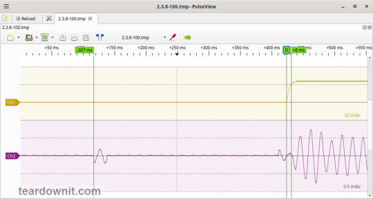
The picture shows three distinguishable phases of the power-on process:
The pulse of the input current charging the input capacitors when connected to the grid has an amplitude of about 2 A and a duration north of the mains voltage period.
Waiting for the power supply control circuit to start for about 300 ms.
(Output Voltage Rise Time) Starting the converter, increasing the output voltage, and entering the operating mode takes 8 ms.
(Turn On Delay Time) The entire process of entering the operating mode from the moment of powering on is 315 ms.
(Output Voltage Overshoot) The switching process is aperiodic; there is no overshoot.
Powering on at 0% load
The power supply is turned off at least 5 minutes before the test, with a 100% load connected. Then, the load is disconnected, and the power supply is switched on. The oscillogram of switching to a 0% load is shown below:
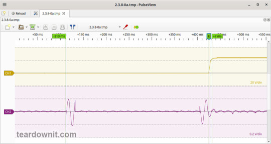
The picture shows three distinguishable phases of the power-on process:
The pulse of the input current charging the input capacitors when connected to the grid has an amplitude of about 2.2 A and a duration slightly longer than one mains period.
Waiting for the power supply control circuit to start for about 300 ms.
(Output Voltage Rise Time) Starting the converter, increasing the output voltage, and entering the operating mode takes 7 ms.
(Turn On Delay Time) The entire process of entering the operating mode from the moment of powering on is 320 ms.
(Output Voltage Overshoot) The switching process is aperiodic; there is no overshoot.
Power-off parameters
The power supply was turned off at 100% load, and the input voltage was nominal at the moment of powering off. The oscillogram of the shutdown process is shown below:
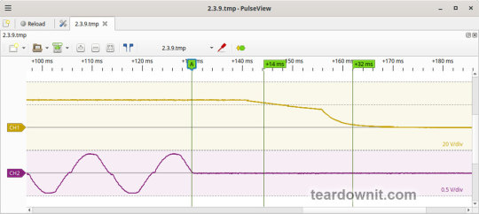
The picture shows two phases of the shutdown process:
(Shutdown Hold-Up Time) The power supply continues to operate due to the input capacitors holding charge until the voltage across them drops to a certain critical level, at which maintaining the output voltage at the nominal level becomes impossible. The phase takes 14 ms.
(Output Voltage Fall Time) Reduction of the output voltage, stopping voltage conversion, and accelerating the voltage drop takes 18 ms.
(Output Voltage Undershoot) The shutdown process is aperiodic; there is no overshoot.
Right before shutdown, the current waveform at 100% load is close to sinusoidal with an amplitude of 4.22 A.
Ripple output voltage
100% load
At 100% load, the low-frequency ripple is approximately 3 mV.

At 100% load, the ripple at the converter frequency is approximately 50 mVp-p, and the noise is 120 mVp-p.
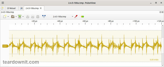
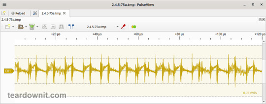
75% load
At 75% load, the low-frequency ripple is approximately 3 mV.

At 75% load, the ripple at the converter frequency is approximately 40 mVp-p, and the noise is 120 mVp-p.
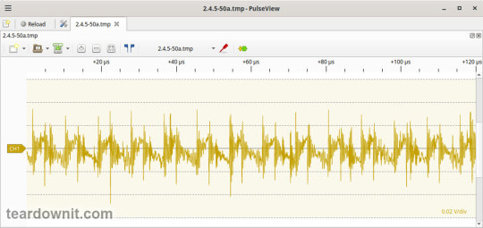
50% load
At a 50% load, the low-frequency ripple is approximately 3 mV.

At 50% load, the ripple at the converter frequency is approximately 30 mVp-p, and the noise is 70 mVp-p.
10% load
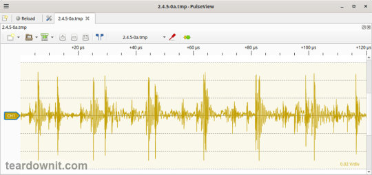
At 10% load, the low-frequency ripple is approximately 2 mV.
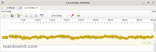
At a 10% load, the ripple at the converter frequency is approximately 20 mVp-p, and the noise is 90 mVp-p.
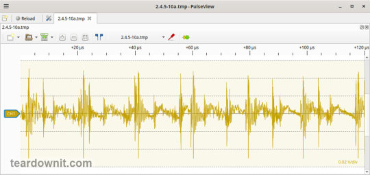
0% load
No-load current consumption measured with a multimeter: 53.5 mA.
(Power Consumption) The first assumption of excessive standby power draw of more than 6.5 watts is wrong since the current in this mode is predominantly reactive. Indeed, the input filter in the circuit contains two capacitors with a combined capacitance of 1.5 μF. Measuring the exact active power consumption at a 0% load with a basic set of instruments (oscilloscope, multimeter, etc.) is impossible.
At 10% load, the low-frequency ripple is approximately 2 mV.
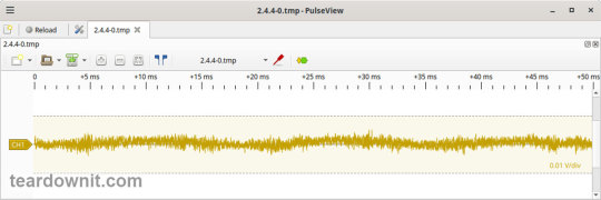
At 10% load, ripples at the converter frequency are masked by the 90 mVp-p noise.
Dynamic characteristics
TA mode with periodic switching between 50% and 100% load was used to evaluate the dynamic characteristics. The process oscillogram is shown below:
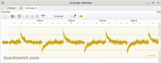
It is evident that the supply’s response to loading changes is close to aperiodic, and there is no overshoot, which indicates a good stability margin. The magnitude of the response to load changes is just 60 mV.
Overload protection
The claimed protection type is "hiccup mode, recovers automatically after fault condition is removed." This was confirmed during testing. When a short circuit occurs, the power supply periodically tries to turn back on and, if the overload is still present, turns off again until the next attempt. This operating mode reduces energy losses and heating during overload. Still, it does not allow the parallel connection of multiple power supplies with a common output.
The output current for the overload protection to kick in is 17 A.
Input circuit safety assessment
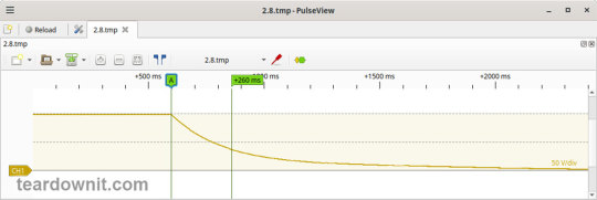
(Input discharge) Safety assessment is based on the discharge time constant of the input circuits when disconnected from the grid; the value is 0.26 s. This means that when operating on a 120 V input voltage, the time required to discharge the input circuits to safe values (<42 V) will be 0.41 s:

Important: The result is valid for this particular power supply unit; it was obtained for testing purposes and should not be taken as a safety guarantee.
The leakage current at the ground pin is less than 10 µA.
Thermal conditions
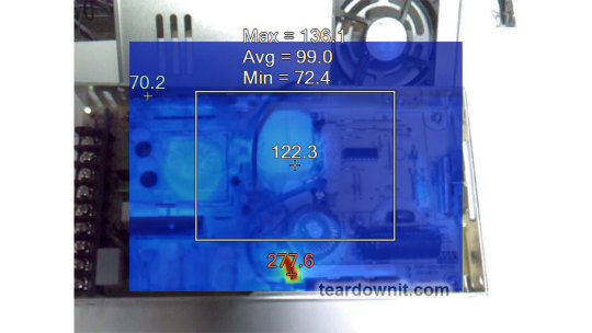
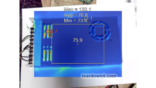
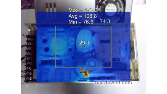
When operating with no load connected, no component overheating had been noticed. Thermograms were captured at three power levels: 80, 90, and 100%, fully assembled and with the lid removed. Thermal images show that the most loaded element of the block is the input diode bridge, and its heating seriously stands out against the background of all the other components.
Unfortunately, already at 80% load, the diode bridge heats up to an unacceptable level of 259°F (126°C), which is dangerous for long-term operation.
80% load
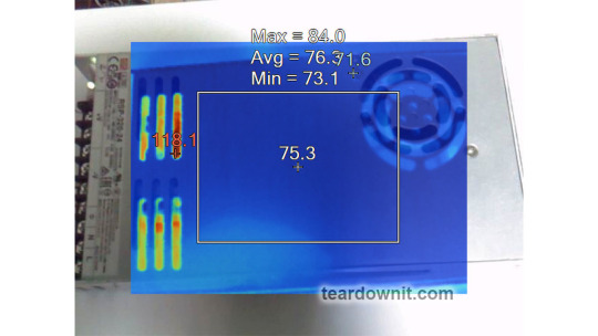
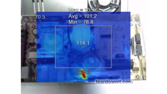
90% load
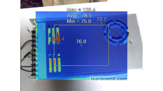
100% load
Conclusions
Overall, the RSP-320-24 is well-built: this power supply has good dynamic characteristics, low noise, and ripple, good accuracy in maintaining the output voltage, and is well put together. The load should be limited to 70–80% of the nominal for long-term operation.
Important: The results are valid for this particular power supply unit; they were obtained for testing purposes and should not be used to evaluate all the units of the same type.
0 notes
Text

Tinned Core Wiring
Ensure durability and top-notch performance with Tinned Core Wiring from LED Advantage. This high-quality wiring is ideal for marine, automotive, and outdoor applications where resistance to corrosion is crucial. The tinned copper core protects against rust and oxidation, ensuring excellent conductivity and long-lasting reliability in harsh conditions, including exposure to moisture and saltwater. Flexible and easy to install, tinned core wiring is perfect for powering lights, electronics, and other essential systems. Available in various gauges to meet your wiring needs, visit LED Advantage to explore our range and ensure safe, dependable electrical connections.
0 notes
Text
Tinned Copper Clad Steel Wire (T-CCS Wire)
Product Specification: 0.08mm-2.5mm
Tinned copper-clad steel wire (T-CCS wire) is what we often call "CP" wire. Tinned copper-clad steel wire is a new type of composite material, which is made of low carbon steel with excellent quality as the core wire, evenly coated with an oxygen-free copper layer by mechanical method, and then plated with a pure tin layer.
Due to the high material purity of each coating, the compactness between the copper coating and tin coating is good. It can be divided into soft state (a) and hard state (H).

0 notes
Text

Remote Robot Lawn Mower Wire Green Safety Cable 3.8mm 3.4mm 2.7mm Signal Cable for Field Lawn Mower
Boundary Wire used for Auto Lawn Mower
The conductor has aluminum core and is coated with copper and tin.
As this cable corresponds to the cable that comes with many new robotic mower it is considered by the
manufacturers of the robot mowers to be adequate for handling the mowers loop signal. An alternative to this cable is our Premium cable of tin-plated copper. To secure the cable in the ground use Grimsholm signal cable holder. Conductor material: Tinned copper clad aluminium Conductor area:1.423 mm2 insulation material: PE Diameter incl insulation: 3.4 mm
0 notes
Text
Types | Uses | Benefits Of Copper Wire
Copper wire, an essential electrical conductor employed in various applications, is common in residential, commercial, and industrial settings. Comprising either single or multiple strands of pure copper, it is safeguarded by insulation materials like polyvinyl chloride (PVC), polyethylene (PE), polypropylene (PP), polyurethane (PUR), or polytetrafluoroethylene (PTFE). This insulation serves as a protective barrier, mitigating the risk of short circuits and potential electrical fires resulting from arcing between wires within a circuit.
Renowned for its exceptional electrical conductivity, copper, an adaptable metal, is widely utilized in electrical projects. Copper wire may also be crafted from copper alloys, with tin-plated copper being a prevalent choice due to its heightened corrosion resistance compared to uncoated copper.
The remarkable conductivity of copper, nearly 90% that of silver, positions it as an optimal material for electronic applications. Additionally, copper exhibits low resistance in comparison to metals like aluminum or steel, making it well-suited for high-powered purposes such as power lines and low-voltage wiring.
Electrical copper wire is the backbone of modern electrical infrastructure, serving as the primary conductor of electricity in residential, commercial, and industrial settings. Its remarkable conductivity, malleability, and corrosion resistance make it an indispensable material for a wide range of applications.
Types of Copper Wire
Beryllium Copper Wire
Beryllium copper wire constitutes a metal alloy crafted from a blend of copper, beryllium, and other elements. Widely employed in electronics, electro-mechanical applications, and the medical industry, this alloy surpasses pure copper in electrical conductivity while preserving exceptional corrosion resistance. Notably, it boasts a superior strength-to-weight ratio compared to most metals, rendering it well-suited for thin wiring applications. This quality enables flexibility while maintaining stability in demanding environments.
Copper Alloy Wire
Copper alloy wire is accessible in both standard and tailored configurations. When deciding on the most suitable option for your requirements, consider manufacturer specifications such as size, tensile strength (measured in psi), and working temperature. Available choices encompass Zirconium, Beryllium, Brass, Bronze, Titanium, and various other metals. The selection of a specific alloy can impact factors like strength, solderability, durability, and the necessity for insulation. Certain suppliers in this field set themselves apart as manufacturers specializing in copper alloy welding wire.
Copper Clad Aluminum Wire
Varieties of this wire are available with varying conductor diameters, insulation types, and jacket thicknesses. Notable features encompass resistance to working temperatures, fire, oil, and ozone. Copper clad aluminum (CCA) wire is constructed with an aluminum core and an external copper cladding, offering conductivity with a lighter weight. CCA proves to be a cost-effective alternative to pure copper wire, providing enhanced strength and greater electrical conductivity compared to pure aluminum wire.
Copper Steel Wire
Copper Clad Steel wire constitutes an electrical wire composed of a steel core enveloped in a copper coating. This enhances the conductor’s robustness and longevity, offering improved protection against electric shock. Its growing popularity in construction projects stems from its cost-effectiveness compared to pure copper alternatives, without compromising on durable performance. Additionally, Copper Clad Steel Wire finds utility in various applications, including connecting intercoms, doorbells, and CCTV systems.
Tinned Copper Wire
This copper wire type that has been coated with a thin layer of tin. This coating provides several benefits, including increased corrosion resistance, improved solderability, and a smoother surface finish. Tinned copper wire is commonly used in a variety of electrical applications, such as power wiring, telecommunications, and electronics.
Nickel Plated Copper Wire
Nickel-plated copper wire is a type of copper wire that has been coated with a thin layer of nickel. This coating provides several benefits, including increased corrosion resistance, improved wear resistance, and a brighter surface finish. Nickel-plated copper wire product is commonly used in a variety of electrical applications, such as power wiring, telecommunications, and electronics. Marine Application of nickel-plated copper wire is a best choice due to its superior corrosion resistance in saltwater environments. It is used in boat wiring, underwater cables, and offshore equipment.
Oxygen-Free Highly Conductive Copper (OFHC) Wire
Oxygen-Free Highly Conductive Copper (OFHC) Wire belongs to the category of copper wire that undergoes processing to minimize oxygen content. This process enhances electrical conductivity and operational strength. OFHC wire finds widespread use in various electrical applications owing to its attributes such as low resistance, high flexibility, and resistance to corrosion or oxidation. Its malleability allows for precise machining into intricate shapes, making it well-suited for precision engineering components.
Titanium Clad Copper Wire
Titanium (Ti) clad copper wire represents an alloyed copper wire renowned for its outstanding conductivity, particularly in corrosive environments. The fusion of titanium and copper not only ensures excellent ductility for shaping and forming but also facilitates seamless weldability for tasks such as connecting, capping, and joining. Widely utilized in desalination, water treatment, power generation, chemical processing, and other sectors requiring both high current-carrying capabilities and robust corrosion protection, titanium clad copper wire serves as a versatile solution.
Uses of Copper Wire in Various Applications
Power Transmission
Copper wires form the backbone of power grids, efficiently transmitting electricity from power plants to homes, businesses, and industries. Copper’s low electrical resistance ensures minimal energy loss during transmission, contributing to overall system efficiency and cost-effectiveness.
Communications and Networking
In the realm of communications and networking, copper wire serves as the foundation for telephone lines, data cables, and Ethernet connections. Its ability to support high-speed data transmission makes it ideal for modern communication infrastructure, enabling seamless transfer of information and connectivity.
Electrical Wiring
Copper is a popular choice for electrical wiring due to its excellent electrical conductivity, malleability, and corrosion resistance. These properties make it well-suited for a variety of electrical applications, including power transmission, electronics, and construction.
Electric Motors
Copper wire is the heart of electric motors, providing the conductive pathways for electricity to generate rotational force. Its durability and ability to withstand high currents make it essential for various motor applications, ranging from industrial machinery to household appliances.
Lighting
Copper wire plays a fundamental role in lighting systems, delivering electricity to light bulbs, lamps, and other lighting fixtures. Its flexibility and ability to be shaped into various forms make it suitable for a wide range of lighting applications, from architectural lighting to residential and commercial lighting.
Heating
Copper wire is also widely used in electric heating systems, including baseboard heaters, underfloor heating, and heat pumps. Its ability to efficiently convert electricity into heat makes it a preferred choice for energy-efficient and comfortable heating solutions.
Benefits of Copper Wire
Copper wire is a versatile and valuable material that offers numerous benefits for a wide range of applications. Here are some of the key advantages of using copper wire:
Excellent Conductivity
Copper possesses exceptional electrical conductivity, surpassing all other metals except for silver. This property makes it an ideal choice for applications where efficient transmission of electrical signals and currents is crucial. Copper wires efficiently convey electricity with minimal loss, ensuring reliable power delivery and data transfer.
Malleability and Ductility
Copper exhibits remarkable malleability and ductility, enabling it to be shaped and drawn into wires of various thicknesses and configurations. This versatility allows copper wires to be easily incorporated into various electrical components, circuits, and wiring systems.
Corrosion Resistance
Copper is naturally resistant to corrosion, making it well-suited for applications in various environments. Unlike other metals that may degrade or rust over time, copper wires maintain their integrity and functionality in humid, salty, or chemically exposed environments.
Heat Resistance
Copper exhibits excellent heat resistance, allowing it to withstand high temperatures without melting or losing its electrical properties. This quality makes copper wires ideal for applications involving heat generation, such as motors, transformers, and power cables.
Recyclability
Copper is a highly recyclable material, contributing to its environmental sustainability. Copper wires can be repeatedly melted down and refined into new wires, reducing the need for mining and processing new copper ore. This recycling process also conserves energy and resources.
Availability and Cost-Effectiveness
Copper is a relatively abundant metal, making it readily available and cost-effective compared to some other conductive materials. This affordability further enhances the appeal of copper wires for various electrical applications.
Safety
Copper is a safe material to work with, posing no significant health or environmental hazards. Unlike some other materials, copper does not emit harmful fumes or release toxic substances during its manufacturing or use.
Conclusion:
In conclusion, various copper wire types boast exceptional electrical conductivity, malleability, corrosion resistance, and heat resistance. The diverse uses of copper wire span power transmission, electronics, construction, and specialized fields, highlighting its versatility. The numerous benefits, including recyclability, availability, and safety, underscore copper wire as a valuable material for electrical applications. Armed with this knowledge, you can confidently choose the most suitable wire for your specific needs.
1 note
·
View note