#mosfet function High voltage mosfet
Explore tagged Tumblr posts
Visit Tumblr Blog
Explore Tumblr blogs with no restrictions, modern design and the best experience.
Last Seen Tumblr Blogs


Fun Fact
There are dozens of funny blogs to kill time on Tumblr.
Text
https://www.futureelectronics.com/p/semiconductors--discretes--transistors--mosfets/dmg1012uw-7-diodes-incorporated-6129534
Mosfet applications, Mosfet transistor, mosfet module, mosfet function
N-Channel 20 V 1 A 0.45 Ω Surface Mount Enhancement Mode Power MosFet - SOT-323
#Diodes Incorporated#DMG1012UW-7#Transistors#Mosfets#transistor mosfet#IC mosfet#Mosfet switch circuit#how mosfet work applications#mosfet module#mosfet function High voltage mosfet#Power mosfet#mosfet circuits#mosfet gate#Types of mosfet
1 note
·
View note
Text
https://www.futureelectronics.com/p/semiconductors--discretes--transistors--mosfets/2n7002k-7-diodes-incorporated-8672685
High voltage mosfet, mosfet function, mosfet switch circuit, mosfet gate
2N7002K Series 60 V 2 Ohm SMT N-Channel Enhancement Mode Mosfet - SOT-23-3
#Transistors#Mosfets#2N7002K-7#Diodes Incorporated#types of mosfet#mosfet applications#High voltage mosfet#mosfet function#mosfet switch circuit#mosfet gate#how mosfet works#Power mosfet
1 note
·
View note
Text
https://www.futureelectronics.com/p/semiconductors--discretes--transistors--mosfets/pmv30xpear-nexperia-7092005
Mosfet applications, mosfet function, mosfet switch, mosfet switch circuit
PMV30XEAR Series 20 V 34 mOhm 490 mW SMT P-Channel TrenchMOS FET - SOT-23
#Nexperia#PMV30XPEAR#Transistors#Mosfets#applications#mosfet function#mosfet switch#switch circuit#MOSFET load switch#Power MOSFET#High voltage mosfet#n-channel mosfet#digital transistors#Transistors Mosfets#transistor switch
1 note
·
View note
Text
https://www.futureelectronics.com/p/semiconductors--discretes--transistors--mosfets/irlml2502trpbf-infineon-4227377
Mosfet circuit, Power mosfet, Audio mosfet, high voltage mosfet, mosfet function
N-Channel 20 V 0.045 Ohm Surface Mount HEXFET Power Mosfet - Micro3
#Transistors#Mosfets IRLML2502TRPBF#Infineon#circuit#Power mosfet#Audio mosfet#high voltage mosfet#mosfet function#Power Mosfet#mosfets#mosfet module#mosfet application#transistor mosfet#switch#mosfet transistor#mosfet gate
1 note
·
View note
Text
https://www.futureelectronics.com/p/semiconductors--discretes--transistors--mosfets/irlr2908trpbf-infineon-9173916
Mosfet amplifier, power mosfet, mosfet applications, mosfet transistor
Single N-Channel 80 V 30 mOhm 33 nC HEXFET® Power Mosfet - TO-252AA
#Infineon#IRLR2908TRPBF#Transistors#Mosfets#amplifier#power mosfet#mosfet applications#IGPT transistor#mosfet function#igbt inverter#High voltage mosfet#Mosfet switch circuit#mosfet gate
1 note
·
View note
Text
https://www.futureelectronics.com/p/semiconductors--discretes--transistors--mosfets/fdb3632-onsemi-9032152
Through Hole N-Channel MOSFET, load switches circuit, Transistors Mosfets
N-Channel 100 V 9 mOhm Surface Mount PowerTrench Mosfet TO-263AB
#Transistors#Mosfets#FDB3632#onsemi#Through Hole N-Channel MOSFET#load switches#Mosfet transistor#power mosfet#High voltage mosfet#mosfet circuits#P-channel#how mosfet works#mosfet function#Transistor mosfet
1 note
·
View note
Text
https://www.futureelectronics.com/p/semiconductors--discretes--transistors--mosfets/si2301cds-t1-ge3-vishay-6369524
How mosfet works, mosfet function, High power mosfet, mosfet switch
P-CH MOSFET SOT-23 20V 112MOHM @ 4.5V - LEAD(PB) AND HALOGEN FREE
#Transistors#Mosfets#SI2301CDS-T1-GE3#Vishay#High voltage mosfet#mosfet function#construction of mosfet#How mosfet works#High power mosfet#mosfet switch#mosfet applications
1 note
·
View note
Text
Transistors, Mosfets, BSP125H6327XTSA1, Infineon
Single N-Channel 600 V 45 Ohm 4.5 nC SIPMOS® Power Mosfet - SOT-223
#Transistors#Mosfets#BSP125H6327XTSA1#Infineon#power mosfet#mosfet applications#mosfet circuits#mosfet uses#how mosfet works#mosfet function#High voltage mosfet#mosfet switch circuit#mosfet gate#mosfets#mosfet module
1 note
·
View note
Text
https://www.futureelectronics.com/p/semiconductors--discretes--transistors--mosfets/stn3nf06l-stmicroelectronics-3775400
Power mosfet, High voltage mosfet, mosfet function, mosfet uses
STN3NF06L Series 60 V 0.1 Ohm N-Channel STripFET™ II Power MosFet - SOT-223
#Transistors#Mosfets#STN3NF06L#STMicroelectronics#Power mosfet#High voltage mosfet#mosfet function#mosfet uses#Mosfet gate#how mosfet works#mosfet transistor#transistor mosfet#Low voltage mosfet#super junction mosfet#high current mosfet
0 notes
Text
VNI4140K Specifications & Features Explained
The VNI4140K is a cutting-edge high-side smart power switch designed for industrial and automotive applications. But what makes it special? Why should engineers and tech enthusiasts care about it? This article dives deep into its specifications, features, and applications, making it easy to understand—even for those unfamiliar with complex electronic components.
What is the VNI4140K?
The VNI4140K is an intelligent quad high-side power switch designed to handle loads with enhanced safety and efficiency. It integrates various protection features, making it ideal for automotive, industrial, and smart control applications.
Key Features of the VNI4140K
Quad-channel high-side switch
Over-temperature protection
Short-circuit protection
Overvoltage clamp
Low power consumption
Diagnostic feedback for fault detection
Technical Specifications
Operating Voltage: 8V – 36V
Maximum Load Current: 2A per channel
On-Resistance (Rds ON): 0.1Ω (typical)
ESD Protection: Yes (IEC 61000-4-2 compliant)
Temperature Range: -40°C to 150°C
Package: PowerSSO-36
Pin Configuration and Functions
The VNI4140K comes in a PowerSSO-36 package with dedicated input, output, and diagnostic pins. Key pins include:
VCC: Power supply input
IN1-IN4: Control inputs
OUT1-OUT4: Output channels
GND: Ground
FAULT: Diagnostic feedback
How the VNI4140K Works
The VNI4140K acts as a smart electronic switch, replacing traditional mechanical relays. It uses MOSFET technology to efficiently control high-current loads while offering built-in safety features. The fault diagnostics system detects and prevents issues like overheating or short circuits.
Advantages Over Traditional Switches
Improved Energy Efficiency: Consumes less power compared to mechanical relays.
Enhanced Durability: Solid-state design minimizes wear and tear.
Faster Response Time: Reacts quicker to input signals.
Integrated Protection Features: Prevents circuit damage due to overcurrent or overheating.
Common Applications
The VNI4140K is widely used in:
Automotive electronics (lighting systems, door locks)
Industrial automation (motor controls, PLCs)
Smart home devices (intelligent power management)
Medical equipment (precision switching for diagnostics and monitoring devices)
Installation and Usage Guidelines
Ensure proper heat dissipation to prevent overheating.
Connect the diagnostic pin to a microcontroller for real-time monitoring.
Use appropriate filtering capacitors to stabilize the power supply.
Avoid exceeding maximum load limits to prevent system failure.
Troubleshooting and Maintenance Tips
Overheating? Ensure proper ventilation and heat sinks.
No output signal? Check control input voltage.
Short circuit detected? Inspect load connections and wiring.
Intermittent operation? Test for voltage fluctuations.
Conclusion
The VNI4140K is a powerful and reliable quad high-side smart switch designed for various industrial and automotive applications. With advanced protection features, low power consumption, and efficient performance, it offers significant advantages over traditional switching solutions. Whether you're an engineer or a tech enthusiast, understanding its specifications and features can help you integrate it effectively into your designs.
0 notes
Text
Bosch VP44 VP30 VP29 Fuel Pump Repair Transistors IRLR2905
Introduction
Bosch VP44, VP30, and VP29 are electronic diesel fuel pumps used in a variety of diesel engines, including those in cars, trucks, and agricultural equipment. These pumps play a crucial role in fuel injection, ensuring the precise delivery of fuel under high pressure. However, over time, these pumps can develop electrical failures, primarily due to faulty transistors inside the electronic control module (ECM). One common solution to repair these fuel pumps is to replace the defective transistors with IRLR2905.
This article explores the role of the Bosch VP44, VP30, and VP29 pumps, the symptoms of failure, and the repair process using the IRLR2905 transistor.

Understanding Bosch VP Fuel Pumps
The Bosch VP series of fuel pumps are electronically controlled rotary pumps that regulate fuel delivery with precision. These pumps are widely used in modern diesel engines due to their efficiency and reliability. They function as a hybrid between traditional mechanical pumps and fully electronic common rail systems.
Key Features of Bosch VP Pumps:
Electronically controlled fuel injection
High-pressure delivery for efficient combustion
Compact design suitable for various diesel engines
Integrated electronic control unit (ECU) for real-time adjustments
Common Failures in Bosch VP44, VP30, and VP29 Pumps
Despite their reliability, these pumps are prone to failure due to electrical component degradation, especially in the ECU. The most common failure points include:
Transistor Burnout – Over time, the MOSFET transistors inside the pump’s ECU can degrade due to heat and electrical stress.
Capacitor Failure – Aging capacitors can lead to voltage fluctuations, causing erratic pump behavior.
Solenoid Wear – The high-pressure solenoid can become weak, leading to poor fuel atomization.
Wiring Issues – Corroded or broken wires can cause intermittent electrical faults.
Symptoms of a Failing VP Pump
Engine Stalling: The engine suddenly shuts down while driving.
Difficulty Starting: The engine cranks but does not start easily.
Loss of Power: Reduced acceleration and overall poor performance.
Error Codes: Diagnostic trouble codes (DTCs) such as P1689, P0216, or P0251 indicate pump failure.
Rough Idling: The engine runs inconsistently at idle.
Role of IRLR2905 Transistors in Fuel Pump Repair
The IRLR2905 is an N-channel MOSFET transistor that is widely used to replace defective transistors in the Bosch VP series pumps. It offers:
High current handling capacity (55A maximum drain current)
Low on-resistance for efficient energy transfer
Robust thermal performance for durability in high-temperature environments
These features make IRLR2905 a perfect replacement for faulty MOSFETs inside the ECU of the VP44, VP30, and VP29 fuel pumps.
Step-by-Step Repair Process Using IRLR2905
Tools and Components Needed:
IRLR2905 MOSFET transistors (replacement parts)
Soldering iron and soldering wire
Multimeter for testing circuits
Heat-resistant tweezers
PCB cleaner and flux
Protective gloves and goggles
Screwdrivers and pliers
Disassembling the Fuel Pump ECU:
Disconnect the battery: Safety first—always disconnect the vehicle’s battery before working on electrical components.
Remove the fuel pump from the engine: Depending on the vehicle, this may require removing covers, hoses, and mounting brackets.
Locate the ECU on the pump: The ECU is usually housed in a sealed metal casing on the side of the pump.
Open the ECU housing: Use a heat gun or small blade to carefully remove the sealant.
Replacing the Faulty Transistors:
Identify the defective MOSFETs: Use a multimeter to check for continuity and resistance values in the existing transistors.
Desolder the faulty transistors: Carefully remove the defective transistors using a soldering iron.
Prepare the IRLR2905 replacement: Apply flux to the board and align the new transistors in place.
Solder the new transistors: Ensure solid and clean solder joints for reliable electrical connections.
Test the circuit: Before reassembling the ECU, verify that all soldered components are functioning correctly.
Reassembling and Reinstalling the Fuel Pump:
Seal the ECU housing: Use an appropriate heat-resistant sealant to protect the board from moisture.
Reinstall the fuel pump: Secure all mounting points and reconnect the hoses and electrical connectors.
Reconnect the battery: Ensure all electrical connections are correctly restored.
Test the vehicle: Start the engine and monitor performance, checking for error codes and smooth operation.
Preventive Maintenance Tips
Regularly check for error codes: Use an OBD2 scanner to monitor ECU performance.
Keep fuel filters clean: Dirty fuel can contribute to pump failures.
Monitor engine temperature: Overheating can accelerate electrical degradation.
Inspect wiring regularly: Ensure no loose or corroded connections exist.
Conclusion
The Bosch VP44, VP30, and VP29 fuel pumps are vital components of diesel engines, but their electronic control modules can fail due to transistor degradation. The IRLR2905 MOSFET provides a reliable replacement solution, restoring pump functionality and extending its lifespan. By following a systematic repair process, mechanics and DIY enthusiasts can save significant costs compared to purchasing a new fuel pump. Regular maintenance and timely repairs can ensure the longevity of these fuel pumps, keeping diesel engines running efficiently.
0 notes
Text
How do constant current LED drivers maintain steady current?
The following are the core mechanisms and technical implementation methods of the constant current LED driver to maintain a stable current, combined with its working principle and key components for explanation:
1. The basic principle of constant current drive
Negative feedback control mechanism
The constant current driver monitors the LED current in real time through the built-in feedback loop (usually obtains the voltage signal through the series sampling resistor) and compares it with the preset reference value.
When the current deviation is detected, the driver chip automatically adjusts the output (such as adjusting the MOSFET switch duty cycle or linear impedance) to return the current to the set value.
Linear constant current and switching constant current technology
Linear constant current: Directly control the current by adjusting the impedance of the transistor or MOSFET, with a simple structure but low efficiency (suitable for low voltage difference scenarios).
Switching constant current: Using the buck, boost or buck-boost topology, the energy transmission is adjusted through high-frequency switching, and the efficiency can reach 80%-90%.
2. Key technologies for maintaining current stability
Precision current sampling and compensation
Use high-precision sampling resistors (such as 0.1Ω-1Ω) to convert the current into a voltage signal, and compare the reference voltage through the error amplifier to achieve a constant current accuracy of ±1%.
Some chips integrate input voltage compensation function to prevent grid fluctuations from affecting output.
Temperature management design
Built-in over-temperature regulation (OTP) function, automatically reducing current when chip temperature exceeds threshold to avoid thermal runaway.
Improve system stability by reducing heat dissipation design (such as high-voltage linear solution).
Anti-interference and protection mechanism
Add filter circuit to input stage to suppress surge voltage and electromagnetic interference (EMI).
Integrated short circuit protection, open circuit protection and reverse voltage protection to prevent abnormal working conditions from damaging LED or driver.
III. Typical application scenarios and dimming function
Dynamic dimming implementation
PWM dimming: Control the average current by adjusting the duty cycle of the switching frequency to avoid color deviation (frequency is usually >100Hz).
Analog dimming: Directly adjust the reference voltage value to change the output current, suitable for scenes without flicker requirements.
Multi-channel intelligent control
High-end chips support multiple independent constant current outputs, each of which can be programmed separately to meet complex lighting needs (such as RGB mixed light).
IV. Advantages and limitations
Advantages:
Ensure LED brightness consistency and long life (avoid rapid light decay caused by overcurrent).
Adapt to wide input voltage range (such as 5V-60V), compatible with a variety of power supply environments.
Limitations:
The linear constant current solution generates a lot of heat and requires additional heat dissipation design; the switch solution has a high cost.
Reference design example
H6901B boost chip: supports 12V-100V input, sets current through external resistors, and has an efficiency of >90%.
SM2082EAS linear chip: built-in over-temperature derating function, suitable for low-voltage applications such as LED light strips.
If you need a specific circuit diagram or selection suggestions, you can further analyze the voltage, power and dimming requirements of the application scenario.

#led car light#car lights#led lights#led auto light#youtube#led headlights#led headlight bulbs#ledlighting#led light#LED
0 notes
Text
DALY Smart BMS 7S 24V 40A Lithium ion Battery Protection Module
DALY Smart BMS 7S 24V 40A Lithium-ion Battery Protection Module
The DALY Smart BMS 7S 24V 40A is a high-performance Battery Management System (BMS) designed for 7-series (7S) Lithium-ion (Li-ion) battery packs. With a 40A continuous discharge capacity, this BMS is ideal for solar energy storage, electric bikes, scooters, portable power stations, and backup power systems.

This BMS provides comprehensive protection, including overcharge, over-discharge, short circuit, and temperature protection, ensuring the safety and longevity of the battery pack. Additionally, its automatic cell balancing function helps maintain equal voltage across all cells, optimizing battery performance and preventing premature degradation.
A key advantage of the DALY Smart BMS is its smart communication support, including UART, RS485, and Bluetooth connectivity. This enables users to monitor real-time battery performance via a mobile app or PC software, allowing access to crucial data such as voltage, current, and temperature for better management and troubleshooting.
Built with high-quality MOSFETs and an efficient heat dissipation system, the DALY Smart BMS ensures stable and reliable operation, even under continuous load. Its compact, durable, and easy-to-install design makes integration seamless for various power applications.
For those seeking a safe, intelligent, and efficient battery protection solution, the DALY Smart BMS 7S 24V 40A is an excellent choice.
Contact
+𝟭 𝟳𝟳𝟵-𝟳𝟳𝟬-𝟯𝟭𝟬𝟵
1585 Beverly CT, Unit 121, Auror
0 notes
Text
Three Key Concepts to Quickly Understand PMOS in MOSFETs
To understand PMOS, we first need to know: what is MOS? MOS stands for Metal-Oxide-Semiconductor Field-Effect Transistor. As the name suggests, M stands for metal, O for oxide, and S for semiconductor. In summary, it is a type of semiconductor device that uses metal and oxide layers.
In electronic circuits, metals are used when conductivity is needed, and insulating materials are used when conductivity is not needed. So, how do we get something that can both conduct and not conduct electricity? The answer is semiconductors.

Today, we are discussing MOS, which is one type of semiconductor. MOS has semiconductor properties that allow it to conduct electricity at times and insulate at others, acting as a switch in the circuit. PMOS is a type of MOS distinguished from NMOS by the channel type.
PMOS Working Principle
(Electronic switch)
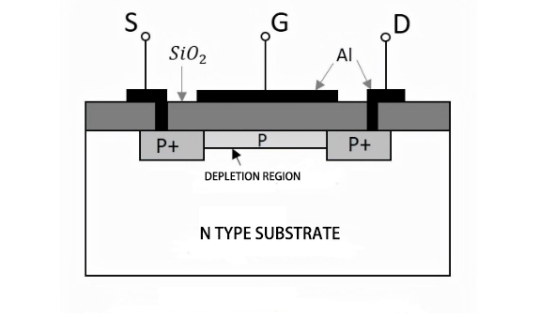
Since PMOS functions as a switch, we need to understand how it turns on and off. First, we need to know that PMOS has an n-type substrate and a p-type channel. The direction of the current is from the source to the drain, carried by the flow of holes.
(Low-Level Drive)
PMOS is a low-level drive circuit, meaning that when the gate-source voltage (Vgs) is below a certain value, it will turn on. This is suitable when the source is connected to VCC (high-side drive). On the other hand, when Vgs is greater than or equal to a certain value, PMOS will turn off. In this way, the gate voltage acts like an invisible hand that controls whether PMOS is on or off by controlling the voltage level, thereby forming or cutting off the current in the circuit. Isn't it fascinating?

Advantages of PMOS
As one of the key players in MOSFETs, PMOS has irreplaceable functions and advantages.
1、Low Noise: PMOS has lower noise than NMOS, making it suitable for use in analog circuits.
2、High Threshold Voltage: PMOS typically has a higher threshold voltage, providing strong interference resistance.
3、Low Power Consumption: In a static state, PMOS has low current loss.
Applications of PMOS in Different Industries
(Large electronic demand households)
Thanks to its advantages, PMOS has penetrated various industries, and you can find its presence in many devices you use every day. In terms of market applications, the number one sector is consumer electronics. Devices like smartphones and tablets, which you are likely familiar with, all feature PMOS. PMOS is mainly used in key components such as microprocessors, memory chips, and display driver circuits, helping these devices maintain long battery life.

The second sector is computer networks, including processors, memory, and routers. PMOS plays roles in data storage, logical computation, and signal regulation. Third on the list are network communications, industrial control, automotive electronics, and power equipment. The demand for MOSFETs in these industries is also high, especially in automotive electronics, which now rivals consumer electronics in MOSFET demand.
Future Development of PMOS
The future development of PMOS transistors will focus on improving performance, reducing power consumption, increasing integration, and expanding application areas. New materials, advanced manufacturing processes, 3D integration technologies, and integration with emerging technologies like artificial intelligence and quantum computing will be the main directions for PMOS development.

0 notes
Text
Slide Switches: Waterproof and Dustproof Design for Extreme Environments

In many high-power applications, a slide switch is not merely a simple switching element but must be capable of providing higher-level protection functionalities, especially in the event of overloads, short circuits, and other abnormal situations. As electronic devices become increasingly power-intensive, the demands on switches are growing. Overload protection and short circuit protection have become key aspects of switch design. This article will delve into the overload protection and short circuit protection design of slide switches in high-power applications, discussing their working principles, design methodologies, and practical applications, along with specific examples.
1. Challenges of Slide Switches in High-Power Applications
In high-power applications, equipment is required to handle large currents and voltages, which demands that the switch not only bear high-power loads but also offer protection capabilities to handle electrical anomalies. Without overload or short-circuit protection, a system could be damaged, cause electrical fires, or even result in personal injury.
For example, in automotive electrical systems, power control devices, industrial machinery, and high-power consumer electronics, switches must effectively prevent excessive current flow or quickly interrupt the circuit in the case of a short circuit, ensuring the safety of the system.
2. Basic Principles of Overload and Short Circuit Protection
1. Overload Protection
Overload occurs when the current exceeds the device or circuit's safe rating. Prolonged overload may lead to component overheating, failure, or even fire. Overload protection in slide switches is typically achieved in the following ways:
Thermal Protection: A common overload protection method involves thermal elements (such as thermal fuses). These elements heat up with increasing current, and when the current exceeds a certain threshold, the temperature rises, causing the fuse to blow and cutting the current to prevent further damage.
Overload Contact Design: Some slide switches incorporate self-resetting overload contacts that prevent contact damage due to overload. In such cases, the switch contacts may physically deform, such as bending or melting, thus automatically disconnecting the circuit.
Electronic Overload Protection: In modern high-power systems, electronic circuits (ICs) are increasingly being used for overload protection. These ICs can monitor the current in real time and disconnect the circuit through components like MOSFETs or relays when an overload occurs.
2. Short Circuit Protection
A short circuit occurs when current finds a low-resistance path in the circuit, creating abnormally high currents that can severely damage electrical components. Short circuit protection aims to quickly identify a short circuit and disconnect the current, preventing damage to the system. Short circuit protection is typically achieved in the following ways:
Fuses: Fuses are commonly used for short circuit protection. When the current exceeds a certain value, the fuse will blow, cutting off the circuit to protect the components from damage.
Circuit Breakers: Similar to fuses, circuit breakers disconnect the circuit in the event of a short circuit. However, unlike fuses, circuit breakers can reset after a fault occurs. When used in combination with slide switches, circuit breakers can quickly respond to a short circuit and provide secondary protection.
Electronic Current Limiting: Electronic current limiting technology is increasingly employed in modern switch systems to protect against short circuits. By incorporating current sensing circuits, the system can reduce the current or cut off the circuit immediately upon detection of a short circuit.
3. Overload and Short Circuit Protection in Slide Switches
In high-power applications, slide switches need to integrate robust overload and short circuit protection features. The following are design strategies for achieving this:
1. Overload Protection Design
High-Temperature Materials: In high-power applications, slide switches must use materials that can withstand high temperatures, such as high-temperature plastics (e.g., PPS, PTFE) and ceramics, to ensure that the switch does not fail due to material degradation under overload conditions.
Thermal Fuses: Some slide switches incorporate thermal fuses inside. When an overload occurs, the fuse blows to disconnect the current and prevent further damage. Thermal fuses are usually designed to be replaceable for easy maintenance.
Thermal Protection and Self-Reset Functionality: Some high-power devices incorporate self-resetting thermal protection in slide switches. Even if the thermal protection element blows and disconnects the circuit, the switch will automatically reset once the temperature normalizes, allowing current to flow again. This design is suitable for devices that experience intermittent heavy loads.
2. Short Circuit Protection Design
Built-in Fuses: To prevent damage from short circuits, slide switches can incorporate micro fuses inside. These fuses will quickly blow when a short circuit occurs, protecting the switch and other electrical components.
Electronic Monitoring Circuits: High-end slide switches often include electronic monitoring circuits that track the current in real-time. Upon detection of a short circuit, the system will immediately disconnect the circuit through components like MOSFETs or relays, providing protection.
Mechanical Circuit Breakers: In industrial control systems, slide switches are often paired with mechanical circuit breakers to ensure that not only does the switch disconnect the circuit in the event of a short circuit, but users can also restore normal operation by resetting the breaker after the fault is cleared.
4. Practical Applications of Overload and Short Circuit Protection
1. Automotive Electrical Systems
In automotive electrical systems, slide switches are commonly used to control various electrical devices, such as lighting systems, onboard power supplies, and air conditioning systems. These systems can have heavy current loads, so switches need to offer both overload and short circuit protection. For instance, in high-power automotive devices (like onboard refrigerators or charging systems), overload protection is essential. If the current exceeds the safe threshold, the switch should disconnect the power to prevent the battery from overheating or the device from being damaged.
By utilizing high-temperature materials in the casing and integrating thermal fuses, the slide switch can cut off the current in the event of an overload. Additionally, electronic current-limiting technology helps reduce current during a short circuit, preventing further damage.
2. Industrial Machinery
In industrial automation, slide switches are often used to control high-power equipment like motors, hydraulic pumps, and industrial conveyors. These devices can experience abnormal current conditions due to overload, short circuits, or mechanical failure. Therefore, overload and short circuit protection are critical.
For example, in some industrial applications, slide switches integrate circuit breakers and thermal protection elements. When overload occurs, the thermal protection element will disconnect the current, preventing the equipment from overheating. At the same time, the circuit breaker will quickly disconnect the circuit in the event of a short circuit, preventing fire hazards or damage to the equipment.
5. Conclusion: Ensuring Safety in High-Power Applications with Slide Switches
In high-power applications, slide switches are not just tools for controlling current; their overload and short circuit protection capabilities are vital for ensuring the system’s stability and safety. Through the use of high-temperature materials, thermal protection mechanisms, electronic monitoring circuits, and safety fuses, slide switches can effectively prevent damage caused by overloads and short circuits, thereby extending the service life of the equipment and safeguarding users.
As the demand for higher power and reliability increases in industrial, automotive, and consumer electronics applications, the design of slide switches will continue to evolve toward more refined and intelligent protection features. This will provide greater safety for various devices, ensuring reliable operation in high-power applications.
en.dghongju.com
0 notes
Text
What Is Three Phase IGBT Inverter?

Hello everyone, we all know that there are three types of inverters, namely single-phase inverters, split-phase inverters and three-phase inverters. The biggest difference between these three inverters is the difference in voltage phase. When learning about inverters, some customers have doubts about IGBT. Today we will share with you what IGBT is and their functions.
First of all, we need to know that IGBT is an insulated gate bipolar transistor, which is a composite fully-controlled voltage-driven power semiconductor device composed of bipolar transistor and an insulated gate field effect transistor. Therefore, its advantages are the high input impedance of MOSFET and the low turn-on voltage drop of GTR. At the same time, the GTR saturation voltage decreases, the current carrying density is large, but the driving current is large; the MOSFET driving power is small, the switching speed is fast, but the conduction voltage drop is large, and the current carrying density is small.
When our machine has a power greater than 7kw, we will choose IGBT technology. We are keen to provide customers with the highest quality products, the best user experience and the most considerate service.
0 notes