#esp32 tutorial
Text
youtube
ESP32 project for beginners with esp32-s2 native usb as Virtual COM port (VCP) serial cdc class usb device
preprocessor assing & check or filter max value of new usb vid pid with macros
ESP32 Arduino Core: Create Custom USB VID & PID for CDC Serial VCP Class Device
#programming#how to#arduino#tutorials#esp32-s2#USB VID#CDC Serial#beginners#Virtual COM port#preprocessor#Youtube
0 notes
Text
DIY: Marauder with Screen and GPS For Flipper Zero
Many of you would have seen the humongous ESP32 add-on module with touch screen and GPS for Flipper Zero shared in discussion groups, forums, etc. Well, this tutorial will provide you with all the information you need to build one yourself.
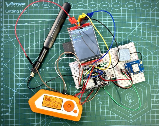
This build consists of mainly 4 parts. The TFT LCD 2.8" 240x320 SPI ILI9341 Touch Display cost me around US$5.50, the ESP32-WROOM-32U module cost around US$3, the NEO-6M GPS module cost around US$2.20 and an 8dbi 2.4GHz Wifi Antenna which cost around US$2. All of these parts can be easily found in online marketplaces like Aliexpress, Amazon, etc.
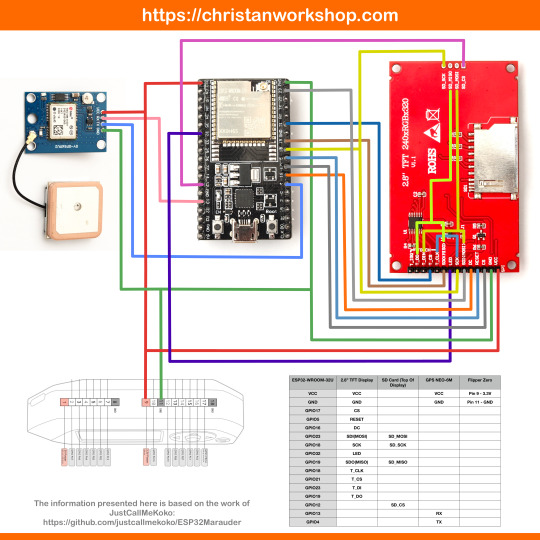
Here is how you need to wire them up together. How you wish to lay this out or mount on a prototyping board is entirely up to you. As long as the connections are correct, you are good to go. The GPS module is optional, and mainly, it's used for the war driving functionality.
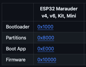
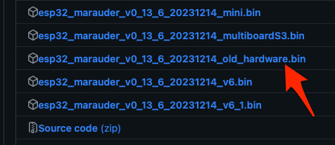
Next, you need to download all the firmware needed from here. Please download the Bootloader, Partitions, Boot App and Firmware files for v4 (Yes, v4 files, not any others) and save it on your computer.
Now, press and hold the BOOT button on your ESP32-WROOM-32U module and connect it to your computer using a data-capable USB cable (some USB cables can only charge), then let go the BOOT button.
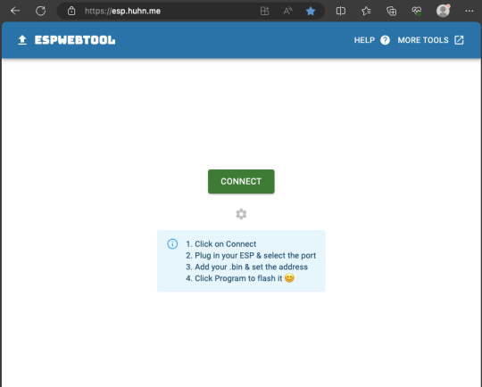
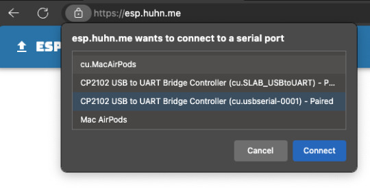
Open Google Chrome or Microsoft Edge browser and go to ESPWebTool. Click the CONNECT button, then select the ESP32 usb serial connection. It should look something like below but can vary a little between different computers and operating systems.
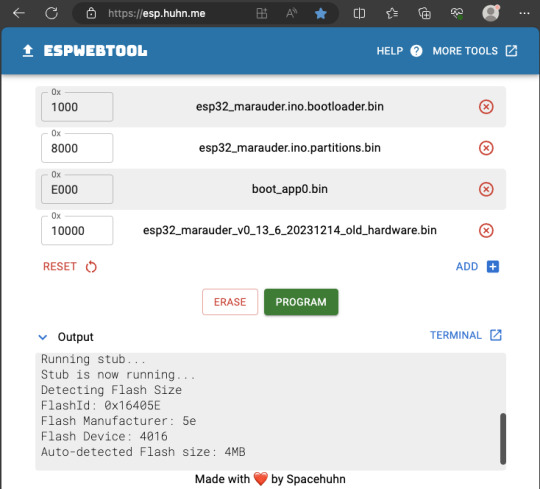
Select the firmware files for each slot exactly like below (take note of the 0x1000, 0x8000, etc. and their corresponding .bin files), then hit the PROGRAM button.
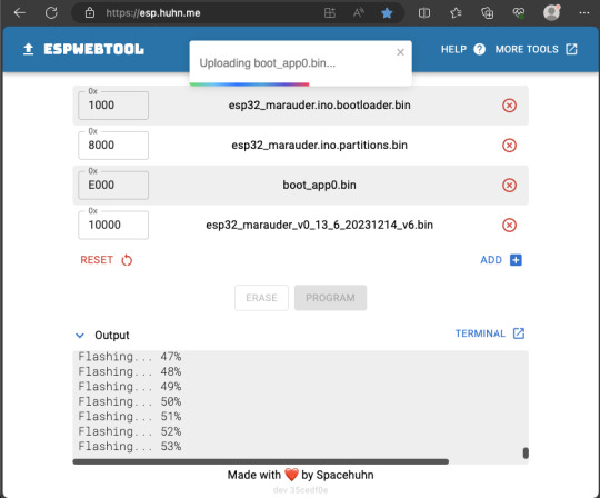
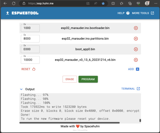
When completed successfully, you can unplug the USB cable from the ESP32 module and now you can connect your Marauder module to your Flipper Zero.
Please ensure that your Flipper Zero is turned off before you connect it, and also turn off your Flipper Zero before disconnecting it. The 3.3V pin is also used by your Flipper Zero's SD card reader and connecting/disconnecting external modules that use this pin while the Flipper Zero is on can potentially corrupt the SD card.
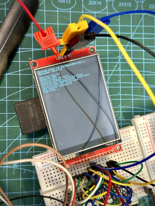
So, if everything went according to plan, your Marauder module should boot up and everything should look like below.
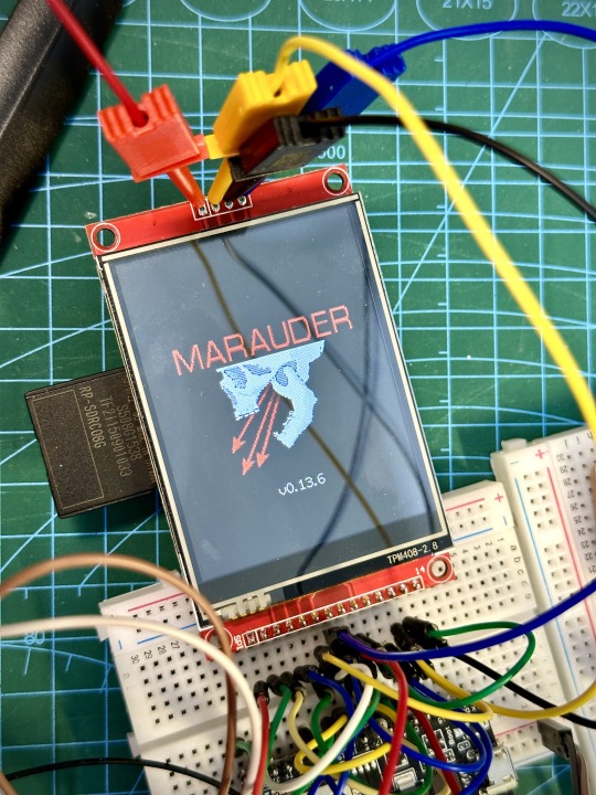
NOTE: If your Marauder boots up, but when you try to touch the screen and get no response, try tapping around the bottom part of your screen and see if the touch panel seems to be in inverted position from the actual display. Should this happen to you, just flash your ESP32 module again following the steps above, but use the v6 firmware. This should resolve the issue.
In this build, I just prototyped this on breadboard, but you can of course make it permanent by soldering it on to a prototype board and 3D print a case for it. This setup is essentially just using the Flipper Zero as a battery pack, instead of using the Flipper Zero to control Marauder.
The large screen does make some things easier to do, compared to the small screen of the Flipper Zero, and there may be some functionality (not much) that is not currently in the Flipper Zero Marauder companion app. Here is a video showing the different menus in Marauder.
Personally, I don't think I will actually want to bring something so big around with me, along with my Flipper Zero. I think what makes Flipper Zero special is just how compact it is and all the different functionality cramped into it. This would probably be better off as a standalone unit by just hooking up a battery, but that's just me.
Well, that's it for this tutorial. I hope you found this helpful.
If you haven’t already done so, check out my Makers & Hackers Exchange Facebook group to learn more from other Flipper Zero users.
Here's a good intro to Marauder if you are unfamiliar.
youtube
11 notes
·
View notes
Text
youtube
Discover the revolutionary world of #Meshtastic, the new tech sensation that's changing the way we communicate off the grid. Move over, Flipper Zero, and welcome to a decentralized communication network that's open-source, free from big brother's watchful eye, and powered by tiny, affordable, and low-powered ESP32 microcontrollers. In this comprehensive video, we dive into everything Meshtastic can do - from encrypted messages over long-range LoRa technology to its applications in rural, mobile, or grid-down scenarios. Learn about the essentials, including how to set up your device, avoid common pitfalls, and even how to extend its range dramatically with a simple antenna upgrade. This video is your guide to understanding how Meshtastic provides a confidential and secure way to communicate, perfect for avoiding wiretapping by telecom giants. Whether you're preparing for a festival, planning a remote adventure, or needing a reliable communication tool for NGO work in areas without cell infrastructure, Meshtastic has you covered. We'll show you what's inside the LoRa 32 box, suggest upgrades for better performance, and take you through the steps to get your device up and running with the latest firmware directly from your browser. Experience an epic range test as we equip a drone with Meshtastic technology, demonstrating the true capabilities of these devices. From setting up the hardware, including choosing the right battery and case, to flashing the Meshtastic firmware and exploring practical use cases, this video is packed with valuable insights. Meshtastic is not just a gadget; it's a versatile tool for secure, encrypted, text-based communication, ideal for skiing, paragliding, camping, and more. Don't miss out on the future of communication. Dive into the Meshtastic world with us, understand its vast potentials, and see if it's the right tech for your next adventure or project. Subscribe for more in-depth tech reviews and tutorials, and join us as we explore cutting-edge technologies that empower you to communicate on your terms.
#make sure to read comments for insights#this is for usa#europe uses different frequency#Meshtastic#off-grid communication#decentralized network#open-source#ESP32 microcontroller#LoRa technology#encrypted messages#range test#drone#firmware flashing#tech review#adventure tech#secure messaging#DIY tech project#Meshtastic setup guide#communication technology.#Youtube
4 notes
·
View notes
Text
A very simple tutorial; like 5 minutes of soldering. The default tutorial sends the data to Adafruit's logging platform, but I'm sure it's possible to set it up to log AQI readings to your own Grafana server or something like that.

Air quality!
3 notes
·
View notes
Text
Sonification of Electricity usage
I have a smart meter with a display in the hall. Trouble is, I hardly ever look at it and the data shows cumulative values rather than the energy being used right now. I had the idea of sonifying the data being recorded by my ESP8826-based electricity monitor. Currently it reports every minute to my sensor dashboard.
I initially thought of running this on an ESP32 or Pi Pico W since both have onboard Wifi which could be used to retrieve the current data from the dashboard. I looked at a few ways to do this, such as using Midi and even ordered a sound module.
However it occured to me that rather than build a device to play the sounds, it could be done as a web page using JavaScript to play the files. At the very least, this would be very useful for testing sonification schemes .
The key HTML feature is the <audio> tag to define the audio resources and the Javascript API to play the audio track. Playing around with this feature, I realised that audio tracks can be looped and can run in parallel and the volume of each track can be changed as the tracks are played.
An update rate of once a minute is too slow to show devices being turned on and off so the ESP8266 monitor was changed to report to another channel every 6 seconds to the dashboard. Only the latest record is recorded on this channel since a full history would be too large. This reading is fetched from the dashboard at the same rate. I'm exploring the idea of multiple sound tracks whose volume is adjusted in response to the level of usage. Currently I'm using six bird songs. Tracks are allocated to bands and as the level of energy usage, measured in watts, increases, tracks are brought into the soundscape with increasing volume.
This approach looks promising because it can be run on a phone and carried around the house, and can be listened to when away from the house. This is the current version. Data fetching and sounds can be turned on and off and the thresholds changed.
The problem now is to design the soundscape and thresholds to best represent the changing energy level.
Other sonification ideas
I'd like to look at getting the national Grid data - obtainable via an API described in https://bscdocs.elexon.co.uk/guidance-notes/bmrs-api-and-data-push-user-guide
This and data from the tree moisture sensor are multi-channel and will need a different approach to generating the soundscape
Extras
Grid in January 2013
Bought this CJMCU-1334 breakout board for playing MP3 files £9
Tutorial
alternatively ESP32 supports BLE which could be used to send MIDI derived sounds to a phone
Free sounds https://freesound.org/
2 notes
·
View notes
Text
MicroPython mit ESP32: DHT11 Sensordaten auslesen und verarbeiten
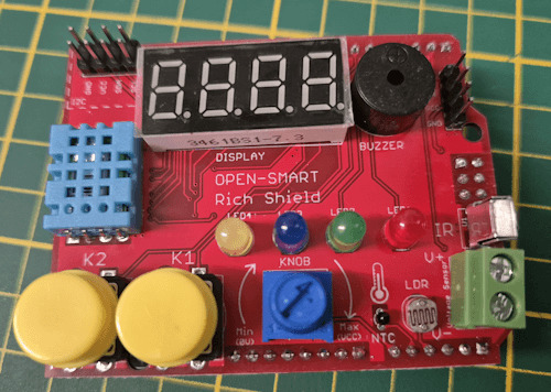
In diesem Beitrag erfährst du, wie man einen Umweltsensor DHT11 am ESP32 D1 R32 mit MicroPython auslesen und diese Sensordaten verarbeiten kann. Für diesen Beitrag verwende ich wieder das Rich Shield von Open Smart. Du kannst jedoch mit wenigen Bauteilen den Sensor an deinen ESP32 anschließen und dieses kleine Tutorial nachbauen.
https://youtu.be/7uvoZU09s78
Der DHT11 Sensor ist eine kostengünstige und weit verbreitete Lösung zur Messung von Temperatur und Luftfeuchtigkeit. Er eignet sich hervorragend für viele DIY-Projekte, wie z.B. die Überwachung von Raumklima, Wetterstationen oder Smart-Home-Anwendungen. In den folgenden Abschnitten zeige ich dir Schritt für Schritt, wie du den Sensor anschließt, die Daten ausliest und auswertest.
Zusätzlich werde ich dir zeigen, wie du die ausgelesenen Sensordaten mit einem Zeitstempel versiehst und in eine CSV-Datei speicherst. Dies ermöglicht eine einfache Weiterverarbeitung und Analyse der Daten, beispielsweise in Tabellenkalkulationsprogrammen wie Excel. So kannst du die Temperatur- und Luftfeuchtigkeitswerte über einen längeren Zeitraum überwachen und Trends erkennen.
Technische Daten des DHT11 Sensors
Mit dem DHT11 Sensor kannst du recht einfach die Temperatur und die relative Luftfeuchtigkeit messen. Dabei ist dieser Sensor nicht nur günstig, sondern auch recht genau. Wie genau dieser Sensor arbeitet, habe ich bereits im Beitrag Vergleich von Temperatursensoren für den Arduino & Raspberry PI aufgezeigt.
relative LuftfeuchtigkeitMessbereich 20 % bis 90 %Toleranz±5 %TemperaturMessbereich 0 °C bis 60 °CToleranz±2 °CBetriebsspannung5V
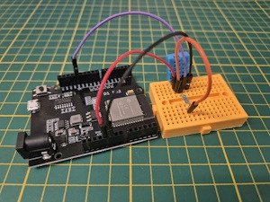
DHT11 Sensor am Rich Shield von Open Smart
Der DHT11 Sensor ist am GPIO19 des ESP32 D12 R32 verbunden (D13 am Arduino UNO).
Mit diesem Umweltsensor kannst du die Temperatur und relative Luftfeuchtigkeit messen. Dabei gibt dieser Sensor alle 1,5 Sekunden einen neuen Wert.
Aufbau der Schaltung ohne Rich Shield von Open Smart
Wenn du die kleine Schaltung ohne Rich Shield nachbauen möchtest, dann gibt es zwei Wege. Zum einen kannst du die Schaltung mit einem fertigen Baustein aufbauen und zum anderen mit dem Sensor und einem 10 kOhm Widerstand.
Hinweis von mir: Die mit einem Sternchen (*) markierten Links sind Affiliate-Links. Wenn du über diese Links einkaufst, erhalte ich eine kleine Provision, die dazu beiträgt, diesen Blog zu unterstützen. Der Preis für dich bleibt dabei unverändert. Vielen Dank für deine Unterstützung!
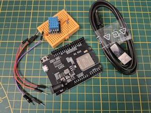
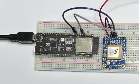
Schaltung mit einem fertigen Baustein
- ein ESP32 D1 R32*,
- ein Micro-USB Datenkabel*,
- ein DHT11 Sensor*,
- drei Breadboardkabel*, 10 cm,
- ein 170 Pin Breadboard*
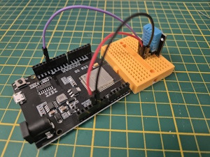
Bei den DHT11 & DHT22 Sensoren auf Platine musst du auf die Beschriftung achten, diese ist immer unterschiedlich. Wenn du deinen Sensor verpolst, dann kann dieser sehr schnell kaputtgehen!

Schaltung - ESP32 D1 R32 mit DHT11 Sensor als Baustein auf einer Platine
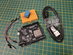
Schaltung mit Sensor & Widerstand
Du erhältst den Sensor auch einzeln, wenn du diesen hast, dann benötigst noch zusätzlich einen 10 kOhm Widerstand, welcher mit VCC verbunden wird.
- ein ESP32 D1 R32*,
- ein Micro-USB Datenkabel*,
- ein DHT11 Sensor*,
- ein 10 kOhm Widerstand*,
- vier Breadboardkabel*, 10 cm,
- ein 170 Pin Breadboard*
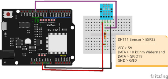
Schaltung - DHT11 Sensor am ESP32 D1 R32 mit Widerstand
Programmieren des DHT11 Sensors in MicroPython am ESP32 D1 R32
Damit wir den Sensor auslesen können, benötigen wir ein zusätzliches Modul. Der Firmware von MicroPython liegt bereits ein passendes DHT Modul bei, mit welchem wir den Sensor DHT11 & DHT22 mit wenigen Zeilen Code auslesen können.
import dht
from machine import Pin, RTC
import time
d = dht.DHT11(Pin(19, Pin.IN))
while True:
d.measure()
print("Temperatur: ", d.temperature(), "°C", sep="")
print("rel. Luftfeuchtigkeit: ", d.humidity(), "%", sep="")
time.sleep(2)
Das kleine Programm schreibt fortwährend die Sensordaten in die Kommandozeile.
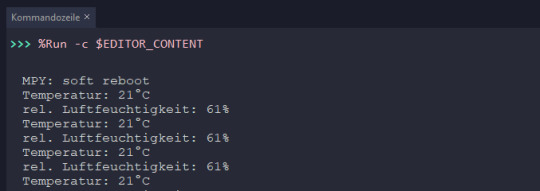
Einfache Ausgabe der Sensordaten in der Kommandozeile
Ausgeben der Daten in einer Tabelle
Die Daten lassen sich auch recht einfach in einer Tabelle auf der Kommandozeile ausgeben. Dazu geben wir als Erstes die Kopfzeile aus und setzen den Trenner (Parameter sep in der Funktion print) auf einen geraden Strich / Pipe.
Zusätzlich hole ich mir noch den aktuellen Zeitstempel von der internen RealTimeClock.
import dht
from machine import Pin, RTC
import time
d = dht.DHT11(Pin(19, Pin.IN))
def getTimestamp():
rtc = RTC()
currentDateTime = rtc.datetime()
hour = currentDateTime
minutes = currentDateTime
seconds = currentDateTime
textFormat = "{0}:{1}:{2}"
if hour < 10:
hour = "0"+str(hour)
if minutes < 10:
minutes = "0"+str(minutes)
if seconds < 10:
seconds = "0"+str(seconds)
return textFormat.format(hour, minutes, seconds)
print("Zeittt","Temperaturt", "rel. Luftfeuchtigkeit", sep="|");
while True:
d.measure()
print(str(getTimestamp())+"t",str(d.temperature())+"°Ctt", str(d.humidity())+"%", sep="|")
time.sleep(2)
Die tabellarische Ausgabe der Sensordaten auf der Kommandozeile hat den Vorteil das wir diese recht einfach ablesen können und wir könnten diese auch markieren und in eine andere Datei formatiert kopieren.
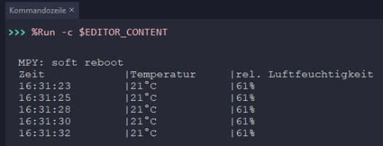
Tabellarische Ausgabe der Sensordaten auf der Kommandozeile
Ausgeben in eine CSV-Datei mit Sensordaten des DHT11 auf dem ESP32 mit MicroPython
Wir können auf dem Mikrocontroller auch Dateien schreiben und so die Sensorwerte aufzeichnen. Wie du Dateien schreibst werde ich dir in einem späteren Beitrag noch genauer erläutern, hier möchte ich dir der Vollständigkeitshalber ein kleines Programm zeigen, welches die Daten vom Sensor in eine CSV Datei mit dem Namen "sensordata.csv" schreibt.
import dht
from machine import Pin, RTC
import time
import os
csvDatei = 'sensordata.csv'
lineBreak = 'rn'
dht11Sensor = dht.DHT11(Pin(19, Pin.IN))
def getTimestamp():
rtc = RTC()
currentDateTime = rtc.datetime()
year = currentDateTime
month = currentDateTime
day = currentDateTime
unknown = currentDateTime
hour = currentDateTime
minutes = currentDateTime
seconds = currentDateTime
textFormat = "{0}.{1}.{2} {3}:{4}:{5}"
return textFormat.format(day, month, year, hour, minutes, seconds)
if not csvDatei in os.listdir():
headline = "Zeit;Temperatur;rel. Luftfeuchtigkeit";
with open(csvDatei, 'w') as f:
print(headline)
f.write(headline)
f.write(lineBreak)
while True:
dht11Sensor.measure()
line = str(getTimestamp())+";"+str(dht11Sensor.temperature())+";"+ str(dht11Sensor.humidity())
with open(csvDatei, 'a') as f:
print(line)
f.write(line)
f.write(lineBreak)
time.sleep(2)
Der Code erstellt auf dem Mikrocontroller die Datei "sensordaten.csv" welche über das Kontextmenü (rechte Maustaste auf der Datei) heruntergeladen werden kann. Zusätzlich wird beim Ausführen des Programmes die Daten auf der Kommandozeile ausgegeben.

Thonny - MicroPython Programm zum aufzeichnen der Sensordaten in eine CSV Datei
Diese CSV Datei kann recht einfach in Microsoft Excel importiert und die Daten verarbeitet und visualisiert werden.
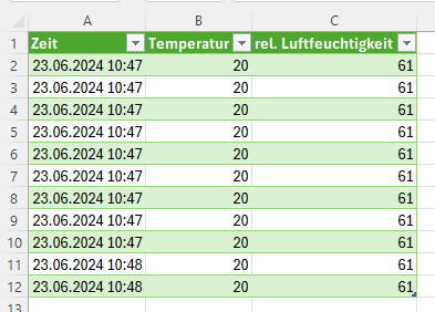
Microsoft Excel - importierte CSV Datei
Ausblick
Die ermittelten Sensordaten könnten wir auch via HTTP Request an ThingSpeak senden und dort extern speichern und visualisieren. Wie du das machst, erläutere ich dir im nächsten Beitrag, sei also gespannt.
Read the full article
0 notes
Text

Build Your Own Breadboard Phone!
“Have you ever wanted to build your own phone from scratch? Preferably on the most ubiquitous electronics prototyping platform for maximum flexibility and minimum ergonomics? Now you can!”
Maker shop SparkFun has a new tutorial on how to literally build your own cellphone from parts — add a SIM card and you can make phone calls with it. If you’ve ever complained about how today's phones are “boring” or “all look the same”, here’s your chance to do something about it.
(It only makes voice calls, but you could add smartphone features — one of those boards is an ESP32 microcontroller, a reasonably powerful computer with WiFi and Bluetooth that you could plug a touchscreen into for another $20 or so.)
It’s not going to be cheaper than a basic off the shelf phone, though. The cellular module (the skinny board between the rabbit ears and speaker) costs $150, and a bunch of other parts are in the $20 range. And you’ll need a case because this isn’t going to stay together after you’ve pulled it out of your purse or pocket a few times.
1 note
·
View note
Text
ESP32 Serial Ports - UART0, UART1, UART2 Access Using the Arduino IDE
The ESP32 has three UART interfaces: UART0, UART1, and UART2. They provide asynchronous, bidirectional communication at up to five Mbps. You can establish serial protocols using the appropriate breakout boards, such as RS232, RS422, RS485, USB, and more.
1 note
·
View note
Text
How do I start my home automation project with iot at low cost?
Take into account the following steps to start an inexpensive IoT home automation project. First, establish your objectives. List the appliances and processes, such lighting, thermostats, or security cameras, that you wish to automate. Choose open-source solutions with flexibility and device interoperability, such as Home Assistant or OpenHAB.
Next, choose IoT devices from embedded that are being classified as automotive embedded or electric vehicles embedded affordable and compatible with your preferred platform. Affordable smart switches and sensors are offered by companies like Sonoff and Shelly. For device communication, use well accepted protocols like MQTT to ensure easy integration.Repurpose current hardware: The controllers can be Raspberry Pi boards or old iPhones. Utilise cloud services that are free or inexpensive, such as Blynk or Cayenne, for remote access. Investigate do-it-yourself options for creating unique sensors or actuators using Arduino or ESP8266/ESP32 boards.
Use tutorials, forums, and internet tools to educate oneself. There is a wealth of knowledge available on IoT and home automation projects on websites like YouTube and GitHub. Engage the neighbourhood to resolve problems and learn more.Consider security when using strong passwords and frequently updating device firmware. As necessary, gradually extend your system while balancing usefulness and expense. With this strategy, you may create a personalised home automation system while keeping costs down and acquiring important IoT experience.
0 notes
Link
0 notes
Text
youtube
WebHID Electron Desktop App Arduino ESP32 USB HID Vendor Basic IO Example Test Demo
Simple basic example Arduinp ESP32 TinyUSB HID device Electron WebHID API Microsoft Windows desktop application test demo USB HID (Human Interface Devices) Vendor feature reports.
#programming#tutorials#arduino#how to#TinyUSB#WebHID#WebHID API#Vendor feature reports#Arduino ESP32#Youtube
0 notes
Text
DIY: ESP32 Cam + ESP8266 Combo Flipper Zero Module
Here is my project for this weekend, a Flipper Zero module with both ESP32 CAM and ESP8266 D1 Mini combined. This allows me to use it for Marauder, Deauther, WiFi Scanner, Camera, Morse Flash, etc. in a single module.
I did consider doing a Mayhem board with NRF24/CC1101, but I find myself rarely using them and Flipper has CC1101 built in anyway (just with shorter range).

The steps to build it is relatively simple. It just combines the two separate modules and some switches to switch between between the two. Below is a quick guide on how I build it.
Note that this is not meant to be a detailed step by step tutorial. If you have some experience with building electronic projects, you should be able to follow along.
Build Steps
Start by cutting the prototype board to the required size and the header pins to the correct lengths (8 & 10 pins). Adjust the position of the plastic thingy holding the male header pins, then bend the pins.


After that, we solder all the header pins to the prototype board and also start soldering the required wires. See the references at the end of this post for all the wiring you need to do to connect the necessary pins.


I used four DPDT switches to switch between the 2 modules. All the required connections from Flipper goes to the switches, then from the 2 poles of the switches to the 2 modules. The same with the antenna as well, as I didn’t want to have 2 separate antennas.
Now is a good time to use a multimeter to check all the connections are good and that there no shorts.


Lastly, we use hot glue to hold the antenna cables securely to the prototype board. Here’s what the completed module looks like.
Now we just need to attach the antennas and insert the ESP32 Cam and ESP8266 modules. Oh, and if you have not mod your D1 Mini to use an external antenna, read this. Flash all the required firmware and test!

Next project, designing and 3D printing a case for this module.
If you enjoy stuff like this, check out our Makers & Hackers Exchange Facebook group
Useful Reference
esp8266_deauther
Flipper Tutorial ESP8266 Deauther v2
ESP32Marauder
flipperzero-mayhem
Flipper Zero ESP32 CAM Camera Module
Flipper-Zero-Camera-Suite
1 note
·
View note
Text
Smart Robot car kit for Arduino UNO R3, 4WD, omnidirectional motion, FPV, ESP32 camera, battery included SunFounder
About SunFounder:
SunFounder is an 11 year old STEAM and Maker education company that helps beginners learn Raspberry Pi, Arduino, ESP32 from zero to hero.
About the Zeus car:
This kit includes easy-to-follow instructions for assembling and coding the robot car. Beginners can complete projects without problems using Online step-by-step tutorials and videos.
Using the 6cm Mecanum wheel, easy…

View On WordPress
0 notes
Text
Liked on YouTube: Powerful Alternative to ESP32 CAM | Realtek AMB82-Mini IoT AI Camera Board - Getting Started
Powerful Alternative to ESP32 CAM | Realtek AMB82-Mini IoT AI Camera Board - Getting Started
𝗔𝗺𝗲𝗯𝗮 𝗔𝗿𝗱𝘂𝗶𝗻𝗼 𝗦𝗗𝗞 𝗽𝗮𝗴𝗲: https://ift.tt/blXFw0c
𝗣𝘂𝗿𝗰𝗵𝗮𝘀𝗲 𝗟𝗶𝗻𝗸: https://ift.tt/O3HePEl
𝗣𝗿𝗼𝗷𝗲𝗰𝘁 𝗗𝗲𝘀𝗰𝗿𝗶𝗽𝘁𝗶𝗼𝗻:
In today's exciting video, we're exploring a power-packed product from Realtek, the AMB82-Mini. This little beast is essentially an IoT AI Camera Arduino Development Board and an impressive replacement for the ESP32 Camera Module.
Designed with Artificial Intelligence, Machine Learning, and Neural Networks in mind, the AMB82-Mini boasts ultra-low power consumption. This makes it incredibly efficient and ensures you won't have to worry about draining your power supply.
What makes this board special? It features an HDR Camera with a crisp 1080p resolution, superior to the ESP32 CAM. The CPU speed is a whopping 500MHz, more than double the ESP32's 240MHz. The AMB82-Mini supports both 2.4 GHz and 5GHz Wi-Fi bands, and also includes a BLE chip that enables Bluetooth Low Energy 5.1. Storage? We've got 768KB ROM, 512KB RAM, 16MB Flash, and support for MCM embedded DDR2/DDR3L memory up to 128MB. Power-packed, isn't it?
In this tutorial, we'll be diving deep into the board design, pin descriptions, features, and capabilities of this remarkable board. We'll also walk you through setting up the Arduino IDE and how to program the AMB82-Mini using this platform. What's more, we'll get hands-on with some practical exercises like making an LED blink, video streaming over a Web server, Object Detection and Identification, and 1080p Video recording.
So, if you're ready to explore the possibilities of IoT, AI, and Machine Learning with this powerful board, hit that play button, and let's get started!
Don't forget to like, share, and subscribe for more tech tutorials and updates. Your support keeps us going! #AMB82Mini #Realtek #IoT #Arduino #AI #machinelearning
𝗪𝗿𝗶𝘁𝘁𝗲𝗻 𝗧𝘂𝘁𝗼𝗿𝗶𝗮𝗹 𝙇𝙞𝙣𝙠𝙨:
𝟭. 𝗚𝗲𝘁𝘁𝗶𝗻𝗴 𝗦𝘁𝗮𝗿𝘁𝗲𝗱: https://ift.tt/WVai2or
𝟮. 𝗢𝗯𝗷𝗲𝗰𝘁 𝗗𝗲𝘁𝗲𝗰𝘁𝗶𝗼𝗻 & 𝗜𝗱𝗲𝗻𝘁𝗶𝗳𝗶𝗰𝗮𝘁𝗶𝗼𝗻: https://ift.tt/lG3HtQ2
𝟯. 𝟭𝟬𝟴𝟬𝗽 𝗠𝗣𝟰 𝗩𝗶𝗱𝗲𝗼 𝗥𝗲𝗰𝗼𝗿𝗱𝗲𝗿: https://ift.tt/ni4OlpS
....................................................................................................................................................................................................................................
Drop a like if you liked this video.
Don't forget to subscribe to our channel for more Electronics projects and tutorials.
Website: https://ift.tt/L7raVJs
Facebook: https://ift.tt/EFchGia
Instagram: https://ift.tt/tQKdAHY
Twitter: https://twitter.com/how2electronics
via YouTube https://www.youtube.com/watch?v=vI6GZMLfGQk
0 notes
Text
MicroPython mit ESP32: Einführung in analoge Sensoren

In diesem Beitrag möchte ich dir jetzt zeigen, wie du analoge Sensoren in MicroPython am ESP32 D1 R32 programmierst und auslesen kannst. Du kannst die nachfolgenden Programme und Schaltungen auch nachbauen, wenn du das Rich Shield von Open Smart nicht hast, ich zeige dir im nachfolgenden Video wie du diese Schaltung aufbaust.
https://youtu.be/D9-9I1fTrEc
Im letzten Video hatte ich dir bereits gezeigt, wie du eine LED via PWM Signal in der Helligkeit regulieren kannst, das Beispiel werde ich hier auch wieder aufgreifen, da du mit einem analogen Drehpotentiometer dieses noch besser umsetzen kannst.
Analoge Sensoren am Rich Shield von Open Smart
Auf dem Rich Shield von Open Smart findest du diverse analoge Sensoren, welche wir auslesen und für kleine Programme verwenden können.
- ein Drehpotentiometer,
- ein NTC Heißleiter,
- ein Fotowiderstand, sowie
- ein Spannungsmesser

analoge Sensorem am Rich Shield von Open Smart
Anschluss der Sensoren am Shield
Nachfolgend biete ich dir eine Tabelle mit den Pins, an welche die genannten Sensoren angeschlossen sind.
analoger SensorESP32 D1 R32Arduino UNO R3DrehpotentiometerIO02 / ADC12A0NTC HeißleiterIO04 / ADC10A1FotowiderstandIO35 / ADC7A2SpannungsmesserIO34 / ADC6A3
Aufbau der Schaltung auf dem Breadboard
Wenn du das Rich Shield nicht hast, jedoch trotzdem das Tutorial hier durcharbeiten möchtest, dann bekommst du nachfolgend den Aufbau der Schaltungen:
- Fotowiderstand
- 10 kOhm Fotowiderstand*
- 10 kOhm Widerstand*
- NTC Heißleiter
- 100 Ohm NTC-Widerstand*
- 10 kOhm Widerstand*
- Spannungssensor / Spannungsteilerschaltung
- 30 kOhm Widerstand*
- 7,5 kOhm Widerstand*

Bauteile - analoge Sensoren auf dem Breadboard

Schaltung - analoge Sensoren am ESP32 R1 D32
Wenn du es jedoch etwas einfacher haben möchtest, dann empfehle ich dir die Sensoren auf einer kleinen Platine. Diese kosten recht wenig und haben den Vorteil, dass du lediglich ein paar Breadboardkabel* an den Mikrocontroller anschließen musst.
- Fotowiderstand*
- NTC Heißleiter*
- Spannungssensor*

analoge Sensoren auf Platine
Hinweis von mir: Die mit einem Sternchen (*) markierten Links sind Affiliate-Links. Wenn du über diese Links einkaufst, erhalte ich eine kleine Provision, die dazu beiträgt, diesen Blog zu unterstützen. Der Preis für dich bleibt dabei unverändert. Vielen Dank für deine Unterstützung!
Auslesen eines analogen Sensors mit MicroPython
Egal ob du ein Drehpotentiometer, NTC-Widerstand oder einen Fotowiderstand auslesen möchtest, du startest immer damit einen analogen Pin zu lesen. Im Falle des NTC-Widerstandes musst du noch eine mathematische Formel anwenden, um aus dem Wert einen Temperaturwert zu erstellen, jedoch die anderen beiden Sensoren können 1:1 ausgelesen und angewendet werden.
# Module zum Zugriff auf die GPIOs
from machine import Pin, ADC
# Modul zum Zugriff auf Funktionen
# wie zum einlegen einer Pause im Code
from time import sleep
# ADC12 am GPIO2, als Eingang
adc_pin = Pin(2, mode=Pin.IN)
# Initialisieren eines ADC Objektes
# (analog digital converter)
adc = ADC(adc_pin)
# Auflösung auf 0..1023 (10bit)
adc.atten(ADC.ATTN_11DB)
# Starten der Endlosschleife
while True:
# auslesen des aktuellen Wertes
print(adc.read())
# einlegen einer Pause von 250 ms.
sleep(0.25)
In diesem Beispiel nutze ich den Drehpotentiometer, wenn dieser nach rechts gedreht wird, erhöht sich der Wert und nach links wird dieser kleiner. Die Range ist hier auf 10bit eingestellt und somit ist der Wertebereich auf 0 bis 1023 beschränkt.
Auslesen des Fotowiderstandes und steuern der Helligkeit einer LED
Im letzten Beitrag hatte ich dir bereits gezeigt, wie du ein PWM Signal erzeugen und damit die Helligkeit einer LED steuern kannst. Im nachfolgenden Beispiel möchte ich dir nun gerne zeigen, wie du den Fotowiderstand auslesen und damit die Helligkeit einer LED steuern kannst.
Ich habe die Werte invertiert, d.h. wenn du den Finger auf den Sensor hältst und der Wert kleiner wird, wird die LED heller.
# Module zum Zugriff auf die GPIOs
from machine import Pin, ADC, PWM
# Modul zum Zugriff auf Funktionen
# wie zum einlegen einer Pause im Code
from time import sleep
# ADC7 am GPI35, als Eingang
adc_pin = Pin(35, mode=Pin.IN)
# Initialisieren eines ADC Objektes
# (analog digital converter)
adc = ADC(adc_pin)
# Auflösung auf 0..1023 (10bit)
adc.atten(ADC.ATTN_11DB)
# rote LED am GPIO17, als Ausgang
led1 = PWM(Pin(17, Pin.OUT))
# Frequenz auf 5 kHz
led1.freq(5000)
# Starten der Endlosschleife
while True:
# auslesen des Sensorwertes
value = adc.read()
# ausgeben des Wertes auf der Kommandozeile
print(value)
# setzen des PWM Wertes
led1.duty(1023 - value)
# eine kleine Pause von 100 ms.
sleep(0.1)
Spannungssensor am Rich Shield in MicroPython programmieren
Am Rich Shield ist ein Spannungssensor verbaut, welchen wir mit nachfolgendem Code auslesen bzw. die Spannung berechnen können. Leider ist dieser nirgends dokumentiert und somit ist mir kein Spannungsbereich bekannt.
# Module zum Zugriff auf die GPIOs
from machine import Pin, ADC
# Modul zum Zugriff auf Funktionen
# wie zum einlegen einer Pause im Code
from time import sleep
# Wert für die Verstärkung des Signals
GAIN = 1.765
# Referenzspannung
# am ESP32 ist diese 3.3V
ADC_REF = 3.3
# ADC6 am GPI34, als Eingang
adc_pin = Pin(34, mode=Pin.IN)
# Initialisieren eines ADC Objektes
# (analog digital converter)
adc = ADC(adc_pin)
# berechnen der Spannung anhand des analogen Wertes
def calVoltage(sensorValue):
return sensorValue * ADC_REF / 1023.00 / GAIN
while True:
# auslesen des analogen Wertes
sensorValue = adc.read()
print("Spannung: ", calVoltage(sensorValue)," V", sep=" ")
sleep(0.5)
Mit meinem Labornetzteil konnte ich bei einem Spannungsbereich von 0 bis 3 Volt die Werte auslesen. Höher wollte ich nicht gehen, damit der Mikrocontroller und-/oder das Shield nicht beschädigt wird.

Spannungssensor vom Rich Shield am ESP32 D1 R32
Besonderheiten des NTC-Widerstandes am Rich Shield mit dem ESP32 D1 R32
Den NTC-Widerstand konnte ich bisher nicht fehlerfrei auslesen. Die Werte, welche ich immer ermittelt habe, lagen ca. 50 % unter den echten, der nachfolgende Code funktioniert und liefert einen ungefähren Wert, welcher nach meinen Prüfungen funktioniert, jedoch ist dieses nicht korrekt, da zum Ende der Berechnung der gemessene Wert lediglich verdoppelt wird.
# Module zum Zugriff auf die GPIOs
from machine import Pin, ADC
# Modul zum Zugriff auf Funktionen
# wie zum einlegen einer Pause im Code
from time import sleep
from math import log
# ADC10 am GPI4, als Eingang
adc_pin = Pin(4, mode=Pin.IN)
# Initialisieren eines ADC Objektes
# (analog digital converter)
adc = ADC(adc_pin)
# Konstanten
SAMPLING_RESISTOR = 10000 # Widerstand des Referenzwiderstands (10k Ohm)
NTC_R25 = 10000 # Widerstand des NTC-Widerstands bei 25°C (10k Ohm)
NTC_B = 3950 # Beta-Wert des NTC-Widerstands
V_IN = 3.3 # Versorgungsspannung in Volt
ADC_MAX = 65535 # Maximaler ADC-Wert (für 10-Bit ADC)
def get_temperature(adc_value):
# Berechne den Widerstand des NTC-Widerstands
resistance = (float(adc_value) * SAMPLING_RESISTOR) / (ADC_MAX - adc_value)
# Berechne die Temperatur in Kelvin mit der Steinhart-Hart-Gleichung
temperature_kelvin = 1 / (log(resistance / NTC_R25) / NTC_B + 1 / 298.15)
# Konvertierung in Celsius
temperature_celsius = temperature_kelvin - 273.15
return temperature_celsius
while True:
adc_value = adc.read_u16() # Beispiel ADC-Wert
print(adc_value)
print("Temperatur: ", get_temperature(adc_value)*2, "°C", sep=" ")
sleep(0.75)
Ausblick
Auf dem Rich Shield ist noch ein Piezo Buzzer verbaut, über welchen man Töne ausgeben kann. Hier werden wir einen kleinen Schritt zurück machen und erneut uns mit dem Thema "PWM Signal am ESP32" beschäftigen. Am Ende wirst du dann befähigt ein kleines Lied über diesen abspielen zu können, sei also gespannt.
Read the full article
0 notes
Text
[Media] ESP32 Wi-Fi Penetration Tool
ESP32 Wi-Fi Penetration Tool
This ESP32 Wi-Fi Penetration Tool is a universal tool for implementing various Wi-Fi attacks on the ESP32 platform. It includes common functionality for Wi-Fi attacks and makes implementing new attacks simpler. Some of its features include PMKID capture, WPA/WPA2 handshake capture and parsing, deauthentication attacks using various methods, denial of service attacks, passive handshake sniffing, and more.
This tool is not intended for cracking hashes, but it can format captured traffic into PCAP format and parse captured handshakes into HCCAPX files ready to be cracked by Hashcat. The project's repository is available on GitHub, and the ESP32-DEVKITC-32E can be purchased online👇
Buy online:
🛒 https://bit.ly/3KQtZqA
🛒 https://amzn.to/43Psdig
#ESP32 #board
YouTubeESP32 Wi-Fi Penetration Tool demoDemonstration video for ESP32 Wi-Fi Penetration Tool project - https://github.com/risinek/esp32-wifi-penetration-tool Enable CC (english) to get more details what's going on in the video. If you are having troubles flashing the tool onto ESP32, you can follow this step by step tutorial by CodexRat https://www.youtube.com/watch?v=dRoXJLPN3RE Darkest Child by Kevin MacLeod is licensed under a Creative Commons Attribution 4.0 license. https://creativecommons.org/licenses/by/4.0/ Source: http://incompetech.com/music/royalty-free/index.html?isrc=USUAN1100783 Artist: http://incompetech.com/

0 notes
Last Seen Blogs

nabludatel23-blog
Без названия

discusstimes
Untitled

moviemagistrate
The Movie Magistrate

kiddjukebox
KITEBOX JUKEBOX

cobain-love27
The duty of the youth is to challange the corupted