#RS 485 chips
Explore tagged Tumblr posts
Text
https://www.futureelectronics.com/p/semiconductors--signal-interface--rs-485-422/sp485ecn-l-tr-maxlinear-9164721
RS-422/485 usb adapter, RS 485 chips, Low EMI Half Duplex RS-485 Transceiver
SP485E Series 10 Mbps 5 V Enhanced Low EMI Half Duplex RS-485 Transceiver-NSOIC8
#MaxLinear#SP485ECN-L/TR#Signal Interface#RS 485/422#485 cable to usb#What is RS-485#communications networks#rs485 cable#RS-422/485 usb adapter#RS 485 chips#Low EMI Half Duplex RS-485 Transceiver#Opto-Isolation#chips#RS 485 cable
1 note
·
View note
Text
What is RS-484, 485 cable to usb, RS 485 cable connector, wireless USB
SP485E Series 10 Mbps 5 V Enhanced Low EMI Half Duplex RS-485 Transceiver-NSOIC8
#MaxLinear#SP485ECN-L/TR#Signal Interface#RS 485/422#RS 485 chips#communications networks#RS-485/RS-422 Transceiver#usb adapter#rs485 cable#RS422 converter#what is RS-484#485 cable to usb#RS 485 cable connector#wireless USB
1 note
·
View note
Text


GB8002 RACK-MOUNT HIGH PRECISION BEIDOU/GPS NTP TIME SERVER GB8002 high precision BeiDou / GPS time server is developed by our company based on GPS timing technology device. It can display and send standard time. The time server uses the PPS and time message of BeiDou Navigation System and GPS (Global Positioning System) satellite to output time synchronization pulse. The device uses SMT surface mount technology for production and high-speed chip for control, with high precision, high stability, strong function, no accumulative error, cost-effective and easy to operate. It is also not limited by geographical and climatic conditions. The device can be widely used in electric power system, network synchronization, communication, traffic management and national defense need timing and punctuality etc. The device has a variety of interfaces. such as RJ45, RS-232, RS-422/RS-485, IRIG-B, TTL Pulse etc. Multi-channel output pulses such as seconds, minutes and hours (free translation), convenient connections and related device, implements unidirectional or bi-directional communication.
FEATURES ■ Provide programmable TTL pulse, can be set to PPS, PPM and PPH, flexible and convenient. ■ 1U Frame structure ,19 inch standard chassis, easy installation and maintenance. ■ All-weather signal coverage to ensure long-term continuous high-reliability high-precision timing. ■ All signal input and output interfaces are photoelectric isolation measures, safe and reliable. ■ High performance, wide range switching power supply, AC-DC compatible input, convenient and reliable, stable operation. ■ Satellite signal receiving and self-service hot standby, according to priority automatically select clock source, seamless switching. ■ The 32-bit high-speed microprocessor + large-scale integrated FPGA chip, parallel high-speed data processing and various codes, excellent performance. ■ Separate 10 M/100M network ports (each port has a separate MAC address), flexible configuration, can be used in different sub-nets or different physical isolation networks, using NTP/SNTP protocols to provide time synchronization services. ■ High-precision punctuality frequency is derived from adaptive synchronization technology, closed-loop control punctuality technology to tame constant temperature crystal oscillator, to achieve long-time high-precision punctuality. ■ Central master clock has 1 channel pulse ,10 channels B code ,3 channels 232 serial port ,3 channels 485 serial port ,2 channels Ethernet. ■ Optional GPS or BeiDou or CDMA three satellite receiving modes, high signal strength, local distributed installation is convenient. Especially suitable for communication base station, power plant, substation, machine room and other equipment time synchronization.
APPLICATION ■ Power plant; ■ Airport time system; ■ Hospital time system; ■ Electric power system; ■ Traffic management system; ■ Radio and television system; ■ Financial insurance company; ■ Network time synchronization; ■ Mobile communication system; ■ Petrochemical iron and steel enterprises;
0 notes
Text
Introduce To Analog Devices ADUM3474ARSZ
PWM Controller and Transformer Driver with Quad-Channel Isolators ADUM3474ARSZ
GENERAL DESCRIPTION The ADuM3470/ADuM3471/ADuM3472/ADuM3473/ ADuM3474 devices1 are quad-channel digital isolators with an integrated PWM controller and transformer driver for an isolated dc-to-dc converter. Based on the Analog Devices, Inc., iCoupler® technology, the dc-to-dc converter provides up to 2 W of regulated, isolated power at 3.3 V to 24 V from a 5.0 V input supply or from a 3.3 V supply. This eliminates the need for a separate, isolated dc-to-dc converter in 2 W isolated designs. The iCoupler chip scale transformer technology is used to isolate the logic signals, and the integrated transformer driver with isolated secondary side control provides higher efficiency for the isolated dc-to-dc converter. The result is a small form factor, total isolation solution. The ADuM347x isolators provide four independent isolation channels in a variety of channel configurations and data rates.
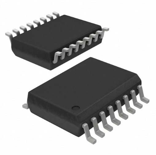
FEATURES Isolated PWM controller Integrated transformer driver Regulated adjustable output: 3.3 V to 24 V 2 W output power 70% efficiency at guaranteed load of 400 mA at 5.0 V output Quad dc-to-25 Mbps (NRZ) signal isolation channels 20-lead SSOP package High temperature operation: 105°C maximum High common-mode transient immunity: >25 kV/µs 200 kHz to 1 MHz adjustable oscillator frequency Soft start function at power-up Pulse-by-pulse overcurrent protection Thermal shutdown
Safety and regulatory approvals UL recognition: 2500 V rms for 1 minute per UL 1577 CSA Component Acceptance Notice #5A VDE certificate of conformity DIN V VDE V 0884-10 (VDE V 0884-10):2006-12 VIORM = 560 V peak Qualified for automotive applications
APPLICATIONS RS-232/RS-422/RS-485 transceivers Industrial field bus isolation Power supply start-up bias and gate drives Isolated sensor interfaces Process controls Automotive
SPECIFICATIONS ELECTRICAL CHARACTERISTICS—5 V PRIMARY INPUT SUPPLY/5 V SECONDARY ISOLATED SUPPLY 4.5 V ≤ VDD1 = VDDA ≤ 5.5 V; VDD2 = VREG = VISO = 5.0 V; fSW = 500 kHz; all voltages are relative to their respective grounds (see the application schematic in Figure 38). All minimum/maximum specifications apply over the entire recommended operating range, unless otherwise noted. All typical specifications are at TA = 25°C, VDD1 = VDDA = 5.0 V, VDD2 = VREG = VISO = 5.0 V.
0 notes
Text
Η Τεχνολογία Της Control4 Πίσω Απο Το Πρωτόκολλο Λειτουργίας Της.

Πρωτόκολλο λειτουργίας της Control4
Τα προϊόντα της Control4 που παρουσιάστηκαν για πρώτη φορά στην εμπορική έκθεση οικιακής τεχνολογίας CEDIA το 2004, ήταν οι πρωταγωνιστές της ευέλικτης επικοινωνίας. Η τεχνική ομάδα της Control4 διαπίστωσε την ευελιξία που προσφέρει η ασφαλής ασύρματη επικοινωνία, και τροποποίησε τη λογική σύνδεσης των συστημάτων της, ελαχιστοποιώντας την ανάγκη εργασιών επισκευής και επιδιορθώσεων. Είναι η πρώτη εταιρία που σύζευξε το ενσύρματο και ασύρματο δίκτυο Ethernet, με την επαναστατική ασύρματη τεχνολογία ZigΒee Pro και το καλωδιακό RS485 σε έναν ενιαίο κορμό λειτουργίας. Ενοποίησε όλους τους σύγχρονους τρόπους σύνδεσης και διαχώρισε κάθε συσκευή της να επικοινωνεί με την ασφαλέστερη και ταχύτερη μέθοδο.
Οπότε όλα τα υλικά που εγκαθίστανται εντός ηλεκτρολογικών πινάκων (dimmers, relays κλπ.) ή όσα απαιτούν πληροφορία ήχου και εικόνας (όπως οθόνες αφής, μπουτονιέρες θυροτηλεόρασης κ.α.) επικοινωνούν ενσύρματα μέσω Ethernet και συνδέονται με κλασικό καλώδιο UTP Cat5e ή ανώτερο.
Οι ασύρματες συσκευές που χρησιμοποιούν τακτικά οι χρήστες και απαιτούν ελευθερία κίνησης με ταυτόχρονη μετάδοση πληροφορίας γραφικών, όπως τα τηλεχειριστήρια, οι εφαρμογές, κ.α., χρησιμοποιούν το δίκτυο WiFi.
Οι ενσύρματες συσκευές που συνή��ως εντοιχίζονται σε εσωτερικούς χώρους, όπως διακόπτες, μπουτονιέρες κ.α., επικοινωνούν μέσω RS-485 και συνδέονται σε σειρά ή ακτινικά μέσω ενός καλωδίου τεσσάρων συνεστραμμένων αγωγών χαμηλής τάσης 48Volt DC. Οι δυο αγωγοί μεταφέρουν την πληροφορία (Data±), ενώ οι άλλοι δύο την τάση λειτουργίας (DC±).
Οι ασύρματες συσκευές που τοποθετούνται σε σημεία που δεν επιδέχονται εργασίες νέας καλωδίωσης, όπως μπουτονιέρες με ενσωματωμένα relay και dimmer κ.α., επικοινωνούν μέσω ZigΒee Pro* και συνδέονται εντός ενός δικτύου προσωπικής περιοχής (PAN) που ρυθμίζεται να έχει συγκεκριμένη εμβέλεια.
Αυτή η μεγάλη επικοινωνιακή ενοποίηση μετέτρεψε αυτομάτως όλες τις συμβατικές κατοικίες σε υποψήφιες ενσωμάτωσης τεχνολογίας smart home, χωρίς όμως το κόστος εργασιών καλωδίωσης και των συνεπακόλουθων εργασιών επισκευής ή επιδιορθώσεων. Έτ��ι δημιουργήθηκε ένα νέο άνοιγμα αγοράς που γρήγορα τροφοδοτήθηκε με αντίστοιχα προϊόντα από όλες τις ανταγωνιστικές εταιρίες.
* Το ZigBee είναι μια ασύρματη τεχνολογία βασισμένη στο πρωτόκολλο IEEE 802.15.4 που αναπτύχθηκε στις αρχές της δεκαετίας του 2000 ως μια εναλλακτική λύση χαμηλού κόστους και κατανάλωσης σε σχέση με τα υφιστάμενα πρωτόκολλα δικτύωσης. Δημιουργεί ένα δικτυακό πλέγμα (mesh networking), στο οποίο τα τηλεγραφήματα αναμεταδίδονται από όλες τις γειτονικές συσκευές του μέχρι να φτάσουν στην τελική, στην οποία απευθύνονται. Το ZigBee έχει σχεδιαστεί με γνώμονα την ανεκτικότητα σε παρεμβολές RF, καθιστώντας το ένα από τα καλύτερα πρότυπα επικοινωνίας για έξυπνα σπίτια, που συνήθως βρίθουν τεχνολογίας.
Ασφάλεια λειτουργίας και επικοινωνίας των συστημάτων Control4
Η Control4 έχει στη φαρέτρα της προϊόντα που καλύπτουν όλες τις ανάγκες των πελάτων της και για όλες τις μορφές επικοινωνίας: ασύρματο δίκτυο WiFi, ενσύρματες συνδέσεις Ethernet (802.3), τη δύναμη του Bluetooth ή του AirPlay ακόμη και του DLNA. Τα επιλεγμένα συστήματα της διαθέτουν συμβατότητα Z-Wave, ώστε να επικοινωνούν με προϊόντα τρίτων κατασκευαστών επιτρέποντας τον χειρισμό τους. Η χρήση του ZigBee Pro ήταν μια επαναστατική επιλογή με άριστα αποτελέσματα στα συστήματα φωτισμού της και ακολουθήθηκε από το σύνολο του ανταγωνισμού.
Με τόσους πολλούς και διαφορετικούς τρόπους σύνδεσης ήταν απαραίτητο η επικοινωνία μεταξύ των προϊόντων της να πραγματοποιείται κωδικοποιημένα και απροσπέλαστα. Όλα τα προϊόντα της Control4 διαθέτουν ένα ενδεδειγμένο chip που είναι υπεύθυνο για την αναγνώριση και απόδοση δικαιωμάτων σύνδεσης στο επιθυμητό δίκτυο. Επιπλέον το πρωτόκολλο λειτουργίας της δεν είναι «ανοικτό», αλλά πλήρως κωδικοποιημένο επιφέροντας αύξηση της ασφάλειας. Ακόμη και οι εμπειρότεροι προγραμματιστές της Control4 δεν έχουν την δυνατότητα ανάγνωσης του δικτύου, των τηλεγραφημάτων που μεταδίδονται ή της δυνατότητας προσθαφαίρεσης συσκευών χωρίς το βασικό πρόγραμμα και τα κλειδιά πρόσβασης που διαθέτει ο ιδιοκτήτης.
Δείτε όλα τα τελευταία άρθρα της Projecting & Sounding Art
#Control4#Control4 automation#smart home automation#smart home solutions#smart home Greece#Αυτοματισμοί Έξυπνης Κατοικίας#Αυτοματισμοί Smart Home#Αυτοματισμοί Σκάφους#Αυτοματισμοί Επαγγελματικού Χώρου#Projecting & Sounding Art#psart
0 notes
Text
Basic structure and control method of LED electronic display screen
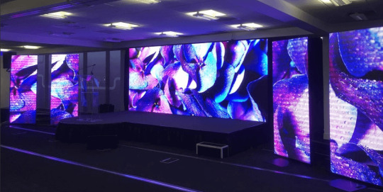
As an efficient information display tool, LED electronic display screen is widely used in advertising, transportation, sports and other fields. Its basic structure and control method are the keys to achieving efficient and clear display. The following is a detailed introduction to the main components of the LED electronic display and its control methods.
Screen structure
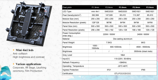
The screen body of the LED electronic display is the core part of displaying information, and is mainly composed of display lattice, row and column drive circuits and other auxiliary circuits. The display dot matrix is usually composed of 8×8 single-color or two-color display units, and various combinations are used to form display screens of various sizes and resolutions. For example, a 32×128 bar screen requires 64 8×8 display units arranged in a 4×16 format. What is an LED box?

Intelligent display unit
The intelligent display unit is a small system that can independently complete the display task and can display Chinese characters, lines and simple graphics. It usually contains a main control microcontroller, RS-485 communication interface, Chinese character library and display buffer, etc. Each intelligent display unit has a unique number or address to facilitate system control and data transmission. Depending on the size and needs of the display, an appropriate number of smart display units can be selected. Provide you with LED display specifications.

Main controller
The main controller is the backbone of the LED electronic display system. It also uses a single-chip microcomputer as the main control device and is equipped with a Chinese character library, a data memory with power-down protection, a real-time calendar clock, and multiple HS-485 communication interfaces. The main controller is responsible for receiving commands and display data from the computer and distributing this information to various intelligent display units while ensuring the synchronization of the displayed content. The main controller allows the LED electronic display system to work independently without relying on an external computer. Take you 5 minutes to understand the LED display control system.
Computers and application software
The computer and its application software are responsible for updating the display content as needed, changing the display mode, and realizing online dynamic display. Since the data display content of the LED display is relatively simple, the amount of data is not large, and the update frequency is not high, the data transmission between the host computer and the lower computer usually uses serial asynchronous communication. The level standard of the communication interface can be selected from RS232, RS422 or RS485 to adapt to different application environments and transmission distances.
Control method
The control methods of LED electronic display mainly include the following aspects:
Synchronous control: Communication synchronization between the main controller and the intelligent display unit ensures the consistency and accuracy of the displayed content.
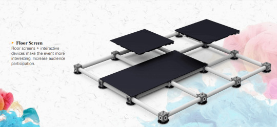
Asynchronous communication: Data transmission with the computer uses serial asynchronous communication to adapt to different communication distances and environmental requirements. Knowledge about synchronous control and asynchronous control of LED display.
Display mode management: Control changes in display modes through application software, such as static display, scrolling display, flashing display, etc.
Content update: The application software on the computer is responsible for generating and updating the display content, transmitting it to the main controller through the communication interface, and then distributing it to each display unit by the main controller.
Through the above structure and control method, LED electronic display screen can achieve efficient, stable and diversified information display to meet the display needs of different occasions.
Thank you for watching. I hope we can solve your problems. Sostron is a professional LED display manufacturer. We provide all kinds of displays, display leasing and display solutions around the world. If you want to know: Small spacing LED display splicer technology. Please click read.
Follow me! Take you to know more about led display knowledge.
Contact us on WhatsApp:https://api.whatsapp.com/send/?phone=8613570218702&text&type=phone_number&app_absent=0
0 notes
Text
Battery charger chips
My studies over the past few months have been about Battery charger chips, general-purpose op amp and Signal Interface, RS 485/422, SP485ECN-L/TR, MaxLinear.
1 note
·
View note
Text
I decided to take a look at that adapter.

Now despite how much I would have liked to insert a wiring diagram, I don't know much about circuitry despite tinkering with it as a child. So images are all you're getting.

A Nexperia 74HC132D Quad 2-input NAND Schmitt trigger chip.

A Texas Instruments LM2937 500-mA Low Dropout Regulator.

And a Maxim Instruments MAX3232 Multichannel RS-232 Line Driver and Receiver, along with a Maxim MAX3491E RS-485/RS-422 Transceivers.
Just based off the chips' positions alone all this adapter seems to be doing is converting RS485 into RS232 and vice versa.
So I have a few electronic marquee signs laying around, I know more now that I did then, lets see if I can get it working
10 notes
·
View notes
Link
MAX3075 Series 500 kbps 6V Half-Duplex SMT RS 485 Transceiver - SOIC-8
1 note
·
View note
Link
Renesas ISL32492EIBZ-T in Reel. ISL32492 Series 5 V RS-485 1/2 Duplex 250 kbps Transceiver - SOIC-8.
1 note
·
View note
Link
STMicroelectronics ST3485EBDR in Reel. ST3485E Series 3.3 V ±15 kV ESD Protected RS-485/RS-422 Transceiver - SOIC-8.
1 note
·
View note
Link
A wide range of UART and USART devices ( single UARTs, DUARTs), LVDS ( LVDS for programming , driver, controller) and USBs (programmable, micro & mini usbs)
1 note
·
View note
Link
Finding quality RS 485/422 chips that enable fast data transmission. They are categorized by data rate, ESD voltage, supply voltage, duplex, function, operating temperature range and more. Explore our selection RS 485/422 line drivers, receivers, transceivers, and transmitters. More options don’t stop you from choosing the right product, as our parametric filter will help you refine the search for easy selection.
1 note
·
View note
Link
ISL83076 Series 3.6 V 20 Mbps (-40 to +85°C) RS-485/RS-422 Transceiver - SOIC-14
1 note
·
View note
Text
Completely independently developed display controller
Brief introduction of PCM-3499 motherboard PCM-3499 is an embedded control module with extremely high cost performance, size and compactness. Almost all the functions required by industrial computers are realized on the PC104 specification board. PCM-3499 onboard embedded high-performance 16-bit processor, which is internally 32-bit RISC architecture and compatible with 80C186 processor, has extremely high performance, main frequency up to 100MHz, built-in 100M Ethernet, and supports 1MB of SDRAM. The instructions are compatible with other X86 microprocessors.
Onboard functions include 10 / 100M high-speed Ethernet interface, PC104 interface, TFT interface and LVDS interface, VGA interface, support standard IDE interface (DOM, ordinary hard disk), parallel port, four serial ports (RS-232 and RS-485, four Each serial port can be configured as TTL level interface), USB interface, DOC interface, PS / 2 keyboard port, RTC real-time clock, ferroelectric, battery-backed SRAM non-volatile memory, watchdog, buzzer interface, general purpose GPIO, 8/16 bit compatible ISA bus, etc. Integrates the system BIOS, 1.44M flash disk
(Flash Flopy Disk-FFD, which can be expanded to 8M flash memory according to user needs) and a 16-point matrix Chinese character library on a single flash memory chip to achieve the smallest size with a minimum number of chips The most functions of the module. Completely independently developed display controller, can achieve up to 1024 768 true color high-performance display effect. If you need more other functions, you can expand the relevant function modules through the PC / 104 bus. Second, PCM-3499 textile controller solution system architecture
In the case of the loom reed suppliers controller successfully developed by Lanyu Technology customers, we briefly introduce one of the customers' textile controller system solutions based on Lanyu Technology PCM-3499. The system architecture is shown in Figure: According to the control realization principle of the entire system scheme shown in the above figure, we divide the main control unit of this scheme into upper and lower computer structures, and PCM-3499 completes the coordination with the upper computer and the control of the terminal equipment . The host computer is mainly responsible for human-computer interaction,
1 note
·
View note