#Ferroelectric R
Explore tagged Tumblr posts
Visit Tumblr Blog
Explore Tumblr blogs with no restrictions, modern design and the best experience.
Last Seen Tumblr Blogs


Fun Fact
Tumblr has 411 employees.
Text
Ferroelectric RAM Market - By Application , By Product With - Forecast(2024 - 2030)

Request Sample Report :
One notable blog that covers F-RAM advancements is All About Circuits. It discusses the latest from Infineon, which has released the EXCELON family of F-RAM chips. This family boasts a high-density serial F-RAM that is energy-efficient and offers fast data retention with minimal power requirements. It’s especially useful in automotive, industrial, and medical devices where data reliability is paramount
All About Circuits
Additionally, Blocks and Files provides an in-depth look at F-RAM’s market prospects, noting that while it has been traditionally used in low-capacity products, newer developments from companies like Micron may help scale its use in more general applications, especially with advancements in its write cycle endurance
Blocks and Files
For those seeking more technical explanations and performance comparisons, Modern Physics also explores the fundamental workings of F-RAM, explaining its physical principles and how it compares to other memory technologies like NAND and DRAM
Modern Physics Insights
If you’re looking to keep up with the latest trends in non-volatile memory and F-RAM specifically, these sources are excellent starting points.
A ferroelectric medium refers to materials that exhibit ferroelectricity, meaning they can retain a permanent electric polarization when exposed to an external electric field, and their polarization can be reversed when the direction of the applied field is changed. These materials are critical in various applications, from memory devices like Ferroelectric RAM (F-RAM) to sensors and actuators.
Inquiry Before Buying :
Ferroelectric materials typically consist of crystals or thin films made from compounds like barium titanate (BaTiO₃) or lead zirconate titanate (PZT). These compounds display a spontaneous electric polarization, which is a key characteristic of ferroelectricity. When an external electric field is applied, the polarization direction aligns with the field, and once the field is removed, the polarization remains in the new direction
The Ferroelectric RAM market can be segmented on the basis of application:
Access control
Energy meters
Security systems
Sensor networks
Smart cards
Schedule A Call :
In terms of product, the Ferroelectric RAM market has been segmented across the following:
Computer desktops
Laptops
Meters
Mobile devices
Personal digital assistants
The market has been segmented based on the following geographies:
North America
South America
APAC
Europe
Middle East
Africa
Sample Companies profiled in this report are:
Cypress Semiconductor
Fujitsu Ltd
Infineon Technologies
International Business Machines
LAPIS Semiconductor
10+.
Buy Now :
In terms of technological development, vendors operating in the market have already invested heavily in R&D of storage technology especially in ferroelectric RAM technology. The technology is expected to be used widely in data centers as well as for wireless sensor operations where data recall will be done wirelessly and hence, speed would have to be of the essence
Key Market Players:
The Top 5 companies in the Ferroelectric RAM Market are:
Infenion Technologies
Fujitsu Ltd
LAPIS Semiconductor
Texas Instruments
IBM
For more Electronics Market reports, please click here
0 notes
Text
0 notes
Text
FM25V05 Series 512 Kb (64 K x 8) 3V Surface Mount Serial F-RAM Memory - SOIC-8
#Memory ICs#RAM#NVRAM#FRAM (Ferroelectric RAM)#FM25V05-G#Cypress#fram memory#fram memory chips#fram memory spi#random access memory#Fram chip#nonvolatile memory#spi fram#FRAM Memory Module#non-volatile memory chips#memory modules#integrated FRAM#Ferroelectric memory#Ferroelectric R
1 note
·
View note
Text
Annals of Chemical Science Research_ Crimson Publishers
Structural, Morphological and Magnetic Studies on Sol-Gel Multi-Doped BiFeO3 Compounds by Costa BFO in Annals of Chemical Science Research
Abstract
The Bi0.8Er0.1Ba0.1Fe0.96R0.02Cr0.02O3 (R = Mn3+ and Co2+) compounds were prepared by the Sol-Gel method and sintered at 800 °C for 2 hours. Both compounds present a rhombohedral structure with R3C space group. The nano-size criteria is confirmed for both compounds. The compound with Mn3+ ions presents the higher saturation magnetization and the higher amount of ferromagnetic contributions.
Keywords: Multiferroics; Sol-gel; Doped BiFeO3; Magnetization; Transmission electron microscopy
Introduction
Materials showing a simultaneous coexistence of electric and magnetic ordering have high interesting properties allowing them to be used in several application arrears especially in next-generation memory devices such as in electric fields control magnetism. These materials are known as multiferroic materials. Among these materials, bismuth ferrite with the general formula BiFeO3 (BFO) stands up, because it is one of the limited materials being simultaneously magnetic and strongly ferroelectric at room temperature [1, 2]. The pure BFO presents an anti-ferromagnetism with Neel temperature around 750K. Indeed, the weak magnetic behaviour and leakage currents are still the drawbacks for its application in the case of novel magnetoelectric effects. However, it was reported that the substitution in A or/and B-sites with suitably doped ions is deemed to be a compromising way to modulate and enhance the ferromagnetic and ferroelectric properties at room temperature of magnetic materials [3-6].
Considering the previous, the discussion of structural, morphological, magnetic and dielectric properties of BFO compound prepared by sol-gel and with the substitution of 10% of Er3+ and 10% of Ba2+ in A-site of BiFeO3 compound simultaneously with 4% of Mn3+ or Co2+ and Cr3+ (2% each one) in its B-site was done [7-9].
Results and Discussion
Structural and morphological studies
X-ray diffractograms of the Bi0.8Er0.1Ba0.1Fe0.96Co0.02Cr0.02O3 (BEBFCC) and Bi0.8Er0.1Ba0.1Fe0.96Mn0.02Cr0.02O3 (BEBFMC) compounds were indexed to bismuth ferrite material with the formula BiFeO3 (JCPDS file no. 71-2494) with rhombohedral structure, R3C space group, which confirms well the formation of the desired perovskite multiferroic material. Furthermore, minor impurity peaks are also evident in the XRD patterns of both compounds. Xpert-hight score was used to prove that these peaks correspond to the Bi2Fe4O9 and Bi25FeO40 phases. The formation of these secondary phases during the synthesis of undoped BFO and cations substituted BFO is almost unavoidable accordingly to similar studies [10,11].
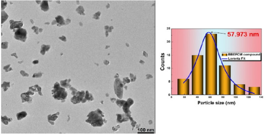
The average crystallite size, estimated from XRD patterns using Scherrer formula was found to be around 68nm and 35nm in the case of BEBFCC and BEBFMC, respectively. The composition and purity of the prepared compounds were determined by energy dispersive X-ray microanalysis. The surface morphology was investigated by scanning electron microscopy and the micrographs showed that the grains are irregular and non-uniformly distributed as in the case of the pure BFO compound [7]. The particle size determination was done by transmission electron microscopy using image-J software, as shown in Figure 1 for BEBFMC. According to a Lorentzian adjustment of the particles size distribution, a value of 57nm was found. One can deduce that each particle has 2 crystallites in average. The nanosized criteria of the prepared compounds was confirmed.
Figure 1: TEM images and particles size distribution of the BEBFMC compound.
Magnetic studies
The temperature dependence of the magnetization under 0.05T of the multiferroic BEBFMC and BEBFCC are shown in Figure 2. One can notice that the magnetization of the BEBFMC compound is higher than that of BEBFCC. Clearly, the magnetization of both compounds, rises when decreasing temperature and shows an inflection point at around 569K and 575K for BEBFMC and BEBFCC, respectively. This temperature is attributed to the Ferromagnetic-Paramagnetic phase transition known as the Curie Weis (TC) temperature. It is important to mention that the TC temperature of the pure BiFeO3 compound was found to be higher than 750K [12], so the utility of the substitution in both A and B sites was confirmed to decrease the TC temperature , especially in the case of Mn ions. The room temperature hysteresis (M(H)) loops of the BEBFMC and BEBFCC compounds are shown in Figure 2, respectively. As one can see, in both compounds, the magnetization occurs in two different behaviours; first region where the magnetization increases very sharply with increasing magnetic field, while at high magnetic fields the magnetization is more-or-less saturated and exhibits a linear behaviour. For pure BFO, the M-H curves exhibit an almost unsaturated straight line which proves that it has a G-type Antiferromagnetic (AFM) with canting of Fe3+ ions [13]. Both behaviours at high and low magnetic fields, confirm the existence of a competition between ferromagnetic (FM) and antiferromagnetic (AFM) interactions due to the substitution in A and B-sites of the BFO compound. This magnetic competition enhances the total magnetization in the studied compound. The saturated magnetization MS of the BEBFMC and BEBFCC compounds were found to be around 6.8 and 5.5emu/g, respectively, at room temperature which is more than seventeen times larger than that of the pure BFO compound (about 0.3 emu/g) [14,15]. This enhancement of magnetization is due essentially due to the FM interactions occurring with the substitutions of both A and B-sites.
The M-H loops have been modulated to quantify theoretically the FM and the AFM contributions, using the following equation:
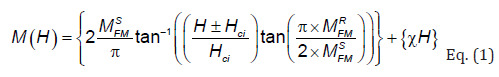
where MFMS, MFMR, Hci are the ferromagnetic saturation magnetization, remnant magnetization, intrinsic coercive field, respectively. The first term in this equation is ascribed to the irreversible component of magnetization, coming from the ferromagnetic contribution (FM). The second one is due to the antiferromagnetic contribution (AFM) and shows a linear behaviour with the applied magnetic field [16,17]. The simulated ferromagnetic and antiferromagnetic contributions at room temperature for both compounds are shown in Figure 2. The resulted fitting parameters are listed in Table 1. From the fitted parameters values, it is concluded that for BEBFMC compound, the AFM contributions are around 34.48% of the total magnetization, while the FM part presents 65.62%, which confirms the domination of the FM contribution over the AFM one. As conclusion, the enhancement of the magnetization in BEBFMC is due especially to the ferromagnetic contribution originated from the substitutions in A and B-sites, while for BEBFCC compound, the AFM contribution dominates the total magnetization (61.3 %) over the FM.
Figure 2: (a) and (b) Magnetization vs. temperature and its first derivation of the BEBFMC and BEBFCC compounds, respectively. (c) and (d) Fit results of the Hysteresis loop at room temperature of the BEBFMC and BEBFCC compounds, respectively.
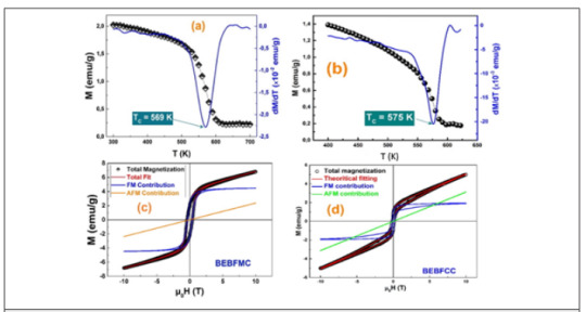
Table 1:Parameters extracted from fitting the magnetization hysteresis loops of the compounds.

Conclusion
The utility of multi doping the BiFeO3 system was confirmed. When introducing a low concentration of Erbium and Barium in A-site with a low amount of Chromium and (Manganese or Cobalt) in B-site, the total magnetization rises more than seventeen times compared to undoped BiFeO3 compound. The Mn3+ ions in B-site enhances the amount of the FM contribution in the compound leading to a rise in magnetization.
#crimson publishers#Annals of Chemical Science Research#Chemistry open access journals#peer reviewed journal of ACSR
0 notes
Photo

Scientists Created a New Solar Cell That Produces 1,000 Times More Power using layered ferroelectric crystals, and are hoping to scale to mass production. via /r/Futurology https://ift.tt/3y1bJ6r
0 notes
Text
Oxygen migration enables ferroelectricity on nanoscale - Breakthrough will enable ferroelectric materials that are smaller than ever (nanoscale) that still retain full functionality

submitted by /u/izumi3682 [link] [comments]
source https://www.reddit.com/r/Futurology/comments/msnn0q/oxygen_migration_enables_ferroelectricity_on/
0 notes
Text
Lithium Tantalate Crystal Market Analysis, Key Players, Growth rate and Future Forecasts 2019-2024

The report presents an in-depth assessment of the Lithium Tantalate Crystal including enabling technologies, key trends, market drivers, challenges, standardization, regulatory landscape, deployment models, operator case studies, opportunities, future roadmap, value chain, ecosystem player profiles and strategies. The report also presents forecasts for Lithium Tantalate Crystal investments from 2019 till 2024.
Development of Lithium Tantalate Crystal /devices deals with the design, fabrication and characterization of Lithium Tantalate Crystal technology across various Lithium Tantalate Crystal application. Current research & development is majorly focused on developing Lithium Tantalate Crystal for applications such as telecommunication, consumer electronics and healthcare.
The report presents the market competitive landscape and a corresponding detailed analysis of the major vendor/key players in the market. Top Companies in the Global Lithium Tantalate Crystal Market:Sumitomo Metal Mining, Shin-Etsu Chemical, Orient Tantalum Industry, Oxide Corporation,Korth Kristalle, SIOM , Castech,CETC, Crystalwise, Shanghai Dongcheng Electronic Materials,United Crystal, Dayoptics.
Click the link to get a free Sample Copy of the Report:
https://www.acquiremarketresearch.com/sample-request/8346/
Lithium tantalate (LiTaO3, LT) crystal is an important ferroelectric material. It has both chemical and mechanical stability as well as a high optical damage threshold. Lithium tantalate exhibits unique electro-optical, pyroelectric and piezoelectric properties combined with good mechanical and chemical stability and wide transparency range and high optical damage threshold. This makes LiTaO3 well-suited for numerous applications including electro-optical modulators, pyroelectric detectors, optical waveguide and SAW substrates, piezoelectric transducers etc.
Lithium tantalate crystal it has excellent piezoelectric electromechanical coupling coefficient, low loss, and high temperature stability, and good high-frequency performance, electro-optical and thermoelectric properties. With the rapid development of communications, information industry development and industrialization of new optoelectronic materials, downstream demand for lithium tantalate crystal keeps increasing.
Lithium tantalite (LiTaO3) is similar to lithium niobate. Both are grown by the czochralski method which yields large, high quality single crystals. Lithium tantalate possesses unique electro-optical, acoustic, piezoelectric and pyroelectric properties, which makes it attractive for numerous applications including electro-optical modulators, pyroelectric detectors, piezoelectric transducers and sensors. It has good mechanical and chemical stability, a wide transparency range and a high optical damage threshold. With the development of 4G LTE, the demand for saw filter will keep on growing in the future, which will promote the demand for lithium tantalate crystal.
The worldwide market for Lithium Tantalate Crystal is expected to grow at a CAGR of roughly 2.3% over the next five years, will reach 190 million US$ in 2024, from 170 million US$ in 2019, according to a new study.
This report focuses on the Lithium Tantalate Crystal in global market, especially in North America, Europe and Asia-Pacific, South America, Middle East and Africa. This report categorizes the market based on manufacturers, regions, type and application.
Global Lithium Tantalate Crystal Market Split by Product Type and Applications:
This report segments the global Lithium Tantalate Crystal Market based on Types are:
Acoustic Grade ,Optical Grade, Other.
On the basis of Application, the Global Lithium Tantalate Crystal Market is segmented into:
Surface Acoustic Wave, Electro-Optical, Piezoelectric Transducers, Pyroelectric,Other.
Regional Analysis for Lithium Tantalate Crystal Market:
For comprehensive understanding of market dynamics, the global Lithium Tantalate Crystal Market is analyzed across key geographies namely: United States, China, Europe, Japan, South-east Asia, India and others. Each of these regions is analyzed on basis of market findings across major countries in these regions for a macro-level understanding of the market.
Inquire for Discount:
https://www.acquiremarketresearch.com/discount-request/8346/
Influence of the Lithium Tantalate Crystal Market report:
-Comprehensive assessment of all opportunities and risk in the Lithium Tantalate Crystal Market.
- Lithium Tantalate Crystal Market recent innovations and major events.
-Detailed study of business strategies for growth of the Lithium Tantalate Crystal Market-leading players.
-Conclusive study about the growth plot of Lithium Tantalate Crystal Market for forthcoming years.
-In-depth understanding of Lithium Tantalate Crystal Market-particular drivers, constraints and major micro markets.
-Favorable impression inside vital technological and market latest trends striking the Lithium Tantalate Crystal Market.
The report has 150 tables and figures browse the report description and TOC:
https://www.acquiremarketresearch.com/industry-reports/lithium-tantalate-crystal-market/8346/
What are the market factors that are explained in the report?
-Key Strategic Developments: The study also includes the key strategic developments of the market, comprising R&D, new product launch, M&A, agreements, collaborations, partnerships, joint ventures, and regional growth of the leading competitors operating in the market on a global and regional scale.
-Key Market Features: The report evaluated key market features, including revenue, price, capacity, capacity utilization rate, gross, production, production rate, consumption, import/export, supply/demand, cost, market share, CAGR, and gross margin. In addition, the study offers a comprehensive study of the key market dynamics and their latest trends, along with pertinent market segments and sub-segments.
-Analytical Tools: The Global Lithium Tantalate Crystal Market report includes the accurately studied and assessed data of the key industry players and their scope in the market by means of a number of analytical tools. The analytical tools such as Porter’s five forces analysis, feasibility study, and investment return analysis have been used to analyze the growth of the key players operating in the market.
Finally, Lithium Tantalate Crystal Market report is the believable source for gaining the Market research that will exponentially accelerate your business. The report gives the principle locale, economic situations with the item value, benefit, limit, generation, supply, request and Market development rate and figure and so on. This report additionally Present new task SWOT examination, speculation attainability investigation, and venture return investigation.
Customization of the Report: This report can be customized as per your needs for additional data up to 3 companies or countries or 40 analyst hours.
Please connect with our sales team ([email protected]).
0 notes
Photo

Reconfigurable two-dimensional optoelectronic devices enabled by local ferroelectric polarization via /r/technology Reconfigurable two-dimensional optoelectronic devices enabled by local ferroelectric polarization Photodetectors based on two dimensional (2D) materials still suffer from low performance.
#IFTTT#reddit Photodetectors based on two dimensional (2D) materials still suffer from low performance. Here#the authors tackle this issue by introducing a reconfigurable design enabled by locally tuning the doping of a 2D molybdenum disulfide film
0 notes
Photo

A possible solution to a long-standing riddle in materials science
All ferroelectric materials possess a property known as piezoelectricity in which an applied mechanical force can generate an electrical current and an applied electrical field can elicit a mechanical response. Ferroelectric materials are used in a wide variety of industrial applications, from ultrasound and sonar to capacitors, transducers, vibration sensors and ultrasensitive infrared cameras. Now, an international team of scientists led by Penn State may have solved the 30-year-old riddle of why certain ferroelectric crystals exhibit extremely strong piezoelectric responses.
In 1997, a relaxor-ferroelectric solid solution crystal with the highest known piezoelectric response was reported at Penn State by Thomas R. Shrout, currently senior scientist and professor of materials science and engineering at Penn State, and the late Seung-Eek Park. It has a piezoelectric response five to ten times higher than any other known ferroelectric material.
"There have been a number of mechanisms proposed to explain its ultrahigh piezoelectric responses, but none of them offer a satisfactory explanation for all the experimental observations and measurements associated with the high response. Without a firm understanding of the underlying mechanism, it would be difficult to design new materials with even higher piezoelectric response," said Fei Li, a postdoctoral scholar in materials science and engineering at Penn State and lead author of a recent article in the journal Nature Communications attempting to explain the phenomenon.
Read more.
37 notes
·
View notes
Text
Tunneling phenomenon is one of the most remarkable and
unique consequences of the wave nature of particles in
quantum mechanics, where a particle can penetrate
through classically forbidden regions. In solids, the quantum
mechanical wavefunctions of electrons form the band structure
separated by the energy gaps, and the tunneling can occur
between these bands when an electric field is applied. This is
called Zener tunneling through the energy gap and has been
actively studied1–13. A concise formula, i.e., Landau–Zener
formula1,2, has been obtained for a model Hamiltonian describing
the two-band system as
H ¼ v_k δ
δ -
v_k
; ð1Þ
where ±vℏk are the energy dispersions and 2δ is the energy gap.
Under an external electric field E, the wavenumber k is acceler-
ated as __
k ¼ -
eE as shown in Fig. 1. The transition probability
from the lower band to the upper band reads
P ¼ exp -
πδ2
e_Ev ; ð2Þ
which is essentially singular with respect to E showing the non-
perturbative nature of the quantum tunneling.
At a pn-junction of semiconductors, the tunneling shows an
asymmetric behavior, which is utilized as a tunneling diode for
rectifying devices14. Because of the broken inversion symmetry,
the tunneling probability, and hence, the I–V characteristics
depend strongly on the direction of the electric field E. For the
uniform bulk crystal, however, the asymmetry in the Zener
tunneling probability is a highly nontrivial issue even when the
crystal lacks the inversion symmetry. This can be seen in the band
dispersion εn(k) (n: band index); the relation εn(k) = εn(−k) holds
due to the time-reversal symmetry even in the absence of the
spatial inversion symmetry. Therefore, the inversion symmetry is
rather hidden in wave mechanics15. Intuitively, the extended wave
state is rather insensitive to the broken inversion symmetry
compared with the localized wave packet. Therefore, a funda-
mental question is how the nonreciprocal behavior, i.e., the
asymmetry between the opposite direction of the electric field E,
is realized in the tunneling processes of the bulk crystals,
reflecting the wave nature of the electrons. This is also an
important issue in terms of device applications; Ferroelectric
random access memory utilizes nonreciprocal current response at
the time of read-out operations of recorded polarization direc-
tion16, while its working mechanism has not been fully under-
stood so far.
The nonreciprocal phenomena in noncentrosymmetric crystals
have been extensively studied in these days, including both the dc
transport17–22 and photo-excited current23–33. In particular, the
no-go theorem has been proposed for the nonreciprocal transport
of independent particles induced by the static electric field, in
terms of a perturbative expansion with respect to E34. Thus
nonreciprocal dc transport requires some sort of interaction
effects in the perturbative regime. On the other hand, this theo-
rem does not apply for the photocurrent induced by the light
irradiation that induces the inter-band transitions, which is called
shift current. The shift current is formulated in terms of the Berry
connection of the Bloch wavefunctions, which correspond to the
intracell coordinates of the electrons30–33,35. The optical transi-
tion causes the shift in the intracell coordinates, i.e., shift vector,
since intracell coordinates are generally different for the valence
and conduction bands in noncentrosymmetric crystals. The
steady pumping of polarization of photoexcited electron–hole
pairs results in the dc photocurrent. Therefore, it is concluded
that the wavefunctions encode the information of the non-
centrosymmetry in sharp contrast to the energy dispersion. In
fact, the Berry phase becomes zero (or trivial) when the system
preserves both the inversion and time-reversal symmetries.
As discussed above, the tunneling is a nonperturbative effect,
and cannot be captured by the perturbative expansion with
respect to E. Hence, it is possible that the nonreciprocal nature
appears in the Landau–Zener tunneling even in the independent
particle approximation. In this paper, we show that this is indeed
the case by deriving the generalized Landau–Zener formula
including the shift vector, i.e., the information of the Bloch
wavefunctions. The generalized Landau–Zener formula shows
that nonreciprocal tunneling generally appears in inversion bro-
ken systems, even in the presence of the time-reversal symmetry.
The nonreciprocity has a geometric origin, dominated by the
Berry connection difference between the valence and conduction
bands. We also give a demonstration of nonreciporcal tunneling
by applying the obtained formula to the Rice–Mele model, an
archetypal one-dimensional model of a ferroelectrics.
Results
Tunneling formula with a shift vector. Let us consider a time
evolution of a system under a slow change of parameters. In
particular, here we focus on a change of momentum k under a
DC electric field, k → k(t) = k − eEt/ℏ. It is well known that the
solution of the time-dependent Schrödinger equation in the
adiabatic limit is given by snapshot eigenstates
HðtÞj i n; kðtÞ ¼ εnðtÞj i n; kðtÞ ð3Þ
multiplied by dynamical and Berry phase factors [see Eq. (4)].
The diabatic correction is derived from the transition dipole
matrix elements. To see this, let us expand a state vector j i Ψ by
the adiabatic solutions as
j i Ψ ¼ X
n
anðtÞe
-
i
R t
t0
dt1½εnðt1ÞþeEAnnðt1Þ=_
j i n; kðtÞ ; ð4Þ
where AnmðtÞ ¼ i nh j ; kðtÞ ∂kj i m; kðtÞ is the Berry connection. (We
note that the “off-diagonal” Berry connections for n ≠ m corre-
spond to transition dipole matrix elements.) With paying atten-
tion in dealing with the Berry phase factor, we can reduce the
time-dependent Schrödinger equation i_∂tj i¼ Ψ HðtÞj i Ψ to
i∂tanðtÞ ¼ eE
_
X
m≠n
jAnmðtÞje
i
R t
t0
dt1½εn-
εmþeERnm=_þi argAnmðt0Þ
amðtÞ;
ð5Þ
with
Rnm ¼ Ann -
Amm -
∂k arg Anm: ð6Þ
See “Methods” for details. Here we have used ℏ∂t = −eE∂k for j i n; kðtÞ and arg AnmðtÞ. Rnm is so called shift vector which is a
gauge-invariant object describing the polarization difference
between two bands n, m30–33,35,36. Specifically, the shift vector
can be interpreted as the spatial shift of the wave packets between
the valence and conduction bands, since the Berry connections
Ann correspond to the intracell coordinates of the Bloch electrons.
It is known that the shift vector plays an important role in bulk
photogalvanic effect in noncentrosymmetric crystals, so called
shift current. The fact that Rnm appears in Eq. (5) is usually
overlooked since Ann = 0 is assumed in many cases. A similar
geometric contribution has also been discussed as the quantum
geometric potential37,38, in the context of the adiabatic condition.
Let us focus on a tunneling process between two bands, n = ±
with a−(t0) = 1, a+(t0) = 0. Our goal is to derive the tunneling
probability P = ∣a+(t)∣
2 after one cycle of the Bloch oscillation.
For simplicity, we consider only the first-order correction w.r.t.
∣A+−∣ here. By integrating Eq. (5) and using it recursively, we
obtain
aþðtÞ ¼ iei arg Aþ-
ðt0Þ
´
Z kðtÞ
k0
dk1 Aþ-
exp -
i
Z k1
k0
dk2
εþ -
ε-
eE þ Rþ-
" #
ð7Þ
with k0 = k(t0), as we detail in “Methods”.
A two-band Hamiltonian can be represented as H = d(k) ⋅ σ
with σ being Pauli matrices (when we subtract a constant energy
shift). The quantities necessary for the evaluation of the tunneling
amplitude are given as
εþ -
ε-
¼ 2
ffiffiffiffiffi
d2 p
; ð8Þ
jAþ-
j ¼
ffiffiffiffiffiffiffiffiffiffiffiffiffiffiffiffiffiffiffiffi
ðd ´ ∂kdÞ
2
q
2d2 ; ð9Þ
Rþ-
¼ ðd ´ ∂kdÞð∂2
kdÞ
ðd ´ ∂kdÞ
2
ffiffiffiffiffi
d2 p
: ð10Þ
In order to evaluate the integral in an asymptotic manner, we
employ the Dykhne–Davis–Pechukas (DDP) method3,4 in
accordance with Ref. 3. Namely, we perform the integral by
means of contour integration in the complex plane. The contour
of the integral, which is originally the real axis [blue lines in
Fig. 2], can be deformed within an analytic region, thanks to the
Cauchy’s integral theorem4,39.
This treatment is advantageous since one can utilize a
(complex) branching point kc, where the energy gap vanishes
dðkcÞ
2 ¼ 0 [Such a point is indeed a branching point when the
Hamiltonian is analytic, as εþ -
ε-
/ ðk -
kcÞ
1=2 in the vicinity
of kc]. This point essentially governs the tunneling process
between the two bands: since the prefactor ∣A+−∣ diverges as we
approach kc [see Eq. (9)], only this divergent part contributes to
the asymptotic value of the integral, when the integration path is
deformed to pass through the vicinity of the branching point kc.
We show the integration path by magenta lines in Fig. 2. The
main part of the contour is one along which the absolute value of
the exponential factor is constant (i.e., the imaginary part of the
k2 integral in Eq. (7) is constant). This contour passes through the
branching point kc, but we make a detour around it since kc itself
is a singular point of the integrand. Due to the divergence
mentioned above, this detoured part contributes dominantly
against the main part. While the branching points appear in a
pairwise manner ðkc; k
cÞ, we need to choose one of them such
that the exponential factor becomes smaller than unity in
accordance with the detailed derivation given in “Methods”. We
note that the integral on the first and last vertical lines have finite
but small contributions in general. They share the same absolute
value (that is perturbative in E) but their phases are different. This
leads to a small oscillation in the tunneling amplitude with
respect to E, on top of the nonperturbative contribution from the
branching point kc. Since we are interested in the nonperturbative
contribution, we neglect those perturbative corrections in the
following.
In a generic situation, one can assume that the leading
order term of d2, ð∂kdÞ
2 and ðd ´ ∂kdÞð∂2
kdÞ in the expansion
around kc is given as d2 ~ iα(k − kc), ð∂kdÞ
2 β, and
ðd ´ ∂kdÞð∂2
kdÞ η, respectively. By evaluating the detoured
part of the integral [circular arc around kc in Fig. 2] with these
expanded forms, we arrive at
P exp 2 Im Z kc
k0
dk2 my most recent read lol
0 notes
Link
Posted by QuantumThinkology via /r/artificial. Join Discussion: https://ift.tt/33RP9xc. Curated by: www.eurekaking.com
0 notes
Photo

Oxygen migration enables ferroelectricity on nanoscale - Breakthrough will enable ferroelectric materials that are smaller than ever (nanoscale) that still retain full functionality via /r/Futurology https://ift.tt/3tElg17
0 notes
Text
Researchers develop new molecular ferroelectric metamaterials

submitted by /u/Gari_305 [link] [comments]
source https://www.reddit.com/r/Futurology/comments/jg517s/researchers_develop_new_molecular_ferroelectric/
0 notes
Link
Authors: Maimon C. Rose, R. E. Cohen
We use molecular dynamics with a first-principles-based shell model potential to study the electrocaloric effect (ECE) in lithium niobate, LiNbO, and find a giant electrocaloric effect along a line passing through the ferroelectric transition. With applied electric field, a line of maximum ECE passes through the zero field ferroelectric transition, continuing along a Widom line at high temperatures with increasing field, and along the instability that leads to homogeneous ferroelectric switching below with an applied field antiparallel to the spontaneous polarization. This line is defined as the minimum in the inverse capacitance under applied electric field. We investigate the effects of pressure, temperature and applied electric field on the ECE. The behavior we observe in LiNbO should generally apply to ferroelectrics; we therefore suggest that the operating temperature for refrigeration and energy scavenging applications should be above the ferroelectric transition region to obtain large electrocaloric response. We find a relationship among , the Widom line and homogeneous switching that should be universal among ferroelectrics, relaxors, multiferroics, and the same behavior should be found under applied magnetic fields in ferromagnets.
0 notes
Text
Piezoelectric and Dielectric Properties of PZT-Epoxy Composite Thick Films-Juniper Publishers
JUNIPER PUBLISHERS- ACADEMIC JOURNAL OF POLYMER SCIENCE
Abstract
Composite piezoelectric thick films are envisioned for energy harvesting, energy storage, and advanced sensor applications. This work focuses on PZT-epoxy-aluminum thick films that were fabricated using a two-step spin coat deposition and annealing method. The volume fraction of the PZT filler ranged from 0.2 to 0.4, and the aluminum volume fraction was varied from 0.10 to 0.17 for each PZT volume fraction, respectively to ascertain the percolation range of the devices and the influence of the aluminum on the device piezoelectric and dielectric properties. An aluminum filler was included in the PZT-epoxy composite to enhance the polarization process of the composite and to enhance the dielectric properties of the composite. The piezoelectric strain coefficients d33 and d31, and capacitance were measured and studied as a function of aluminum volume fraction and top electrode material (silver and gold). It was determined that beyond a critical volume fraction of aluminum, the aluminum particles formed conductive pathways within the composite (percolation threshold region) which diminished piezoelectric strain coefficients beyond the percolation threshold value. The percolation thresholds for these samples were found to occur from 0.13 and 0.17 volume fraction of aluminum, which agrees with theoretical predictions. SEM micrographs were used study the interactions between various phases of the composite.
Keywords: Aluminum; Thick films; Silver; Biomedical
Abbrevations: MOD: Metal Organic Decomposition; MOCVD: Metal Organic Chemical Vapor Deposition; PLD: Pulsed Laser Deposition; SEM: Scanning Electron Microscopy
Introduction
Ferroelectric films have been of interest over the last 20 years because of the possibility of using them for non-volatile memory applications [1-3], MEMS [4-6], ultrasonic devices [4,7], battery separators [8-10], biomedical scaffolds [11] and energy harvesting devices where they are coupled with batteries [12]. The properties if piezoelectric films cannot be compared directly with those of bulk materials of the same composition because their processing and electrical properties differ. Previous work on the preparation of piezoelectric films includes RF planar magnetron sputtering [13,14], ion beam sputtering [15] or DC magnetron sputtering [16], where most recently, researchers have succeeded in fabricating films using various chemical methods of deposition such as; metal organic chemical vapor deposition (MOCVD) [17- 19], chemical solution deposition [20,21], metal-organic decomposition (MOD) [22,23], and also pulsed laser deposition (PLD) [24-26]. The sol-gel method has the benefits of compositional control, reduced temperature processing of highly uniform, dense, crack-free films and low cost of fabrication [27,28]. These methods of processing ferroelectric films have been used with notable success to produce piezoelectric ceramic films comprised of Lead Zirconate Titanate (PbZrxTi1-xO3 also known as, PZT). PZT has a high dielectric constant, ferroelectric, piezoelectric, and pyroelectric properties. The ideal properties of PZT have made its application to transducer, sensor and actuator devices ubiquitous. However, the poor mechanical strength of these devices has limited their life cycle and performance. Therefore, interest in polymer-ceramic [29-33] (and ceramic-ceramic [34,35]) composites has emerged as an area of interest because polymers are flexible, low cost, easily processed [36,37] and able to be polarized under the influence of an external electric field [38].
Piezoelectric ceramic/polymer composites possessing various connectivity patterns have been the focus of much study over the past several years [34, 35, 39-42]. Among the composites examined, the simplest types are those with 0-3 connectivity [39,43]. Piezoelectric composites with 0-3 connectivity consist of piezoelectric ceramic particles dispersed in a three dimensionally connected matrix [1, 5, 29-32, 34, 35, 44-48]. The advantages of these composites lie in the ease in which they may be processed into fairly complex shapes, including but not limited to thin sheets, molded shapes and extruded bars and fibers [39]. The most documented of piezoceramics used in composites such as these is PZT [4, 20, 42, 49-52].
Banerjee et al., [34] studied the influence of aluminum inclusions on the dielectric properties of three-phase PZT cement aluminum composites, where the aluminum and PZT particles were dispersed in a Portland cement matrix. The fabricated samples were nominally 6mm in thickness and were poled at a low poling voltage of 0-6kV/mm at a temperature of 160 ͦC in air. It was reported that three-phase composites possessed a higher piezoelectric strain coefficient (d33) than two-phase composites. The highest value of d33 observed for the three-phase composite was 8.1 pC/N for volume fractions equal to 0.7 and 0.2 for PZT and Al, respectively. This d33 value for the three-phase piezoelectric composite was 1.64 times the value measured for the two-phase composite. Banerjee et al., [53] also investigated the influence of micro and nano sized aluminum inclusions in a three-phase PZT-Epoxy-Al bulk composite. The fabricated composites were ~ 6mm thick and were comprised of micron sized aluminum powder and PZT. These devices had higher dielectric constants that the composites that incorporated nanosized aluminum particles (both sets of samples were polarized at the same value: 0.2 kV/mm in air) due to interfacial effects, contact resistance and increased agglomeration. Specifically, for composites with PZT volume fractions equal to 0.20, 0.30 and 0.40 and micron- sized aluminum particles, the dielectric constants were equal to 405.7, 661.4, and 727.8 (pC/N), respectively. On the other hand, the dielectric constants for composites that were comprised of nano sized aluminum particles the (the same PZT volume fractions) dielectric constants were equal to 233.28, 568.81, and 657.41 (pC/N), respectively. They concluded that samples that contained micron sized aluminum inclusion yielded higher dielectric constant values compared to the Nano sized aluminum inclusions, which resulted in higher dielectric values for samples with micron sized piezoelectric fillers.
In this work, PZT-aluminum-epoxy thick film composites were fabricated where the volume fractions of PZT and Al were varied from 0.20 to 0.40 (increments of 0.10) and 0.0 to 0.17, respectively. A minimum of three samples were fabricated for each of the studies. In addition, two different types of top electrodes (sputtered gold and silver paint) were prepared and compared in terms of piezoelectric and dielectric constants. The change in the piezoelectric and dielectric properties with respect to time was also observed over a five-day period.
Materials and Methodology
The materials used in all experiments were PZT powder (READE), DGEBA Epofix TM Cold-Setting embedding resin (Electron Microscopy Sciences) [54], and aluminum -99.97%, 200 mesh i.e. ~ 75μm (Acros Organics) and 0.0254mm stainless steel substrates (Alfa Aesar). The piezoelectric and physical properties of the materials are presented in Table 1 & 2, respectively. The properties for the aluminum were obtained from the manufacturer website [55,56].
*Experimental values
PZT epoxy aluminum thick composite films were deposited onto stainless steel substrate using a spin coat and deposition technique. The stainless-steel squares were 25mm x 25mm and 0.0254mm thick. An overview of the fabrication process for the devices is provided in Figure 1. The volume fractions of the PZT and aluminum were varied from 0.20 to 0.40 and 0.01 to 0.17, respectively. As shown in Figure 1, the PZT, aluminum and epoxy were weighed to achieve the desired volume fraction and then combined in a beaker. The contents in the beaker were hand stirred for 5minutes and 5ml of ethanol was added to this mixture. The mixture was subsequently sonicated in an ultra sonicator for 1hour, while being hand stirred every 15minutes. The epoxy hardener was then added to the mixture. The final compound was then poured onto the stainless-steel substrate using a dropper while the spin coater was rotated from 100 - 500rpm for 30seconds, and subsequently by 1000rpm for 60seconds. The initial low rpm enabled an even distribution of the compound over the substrate.
After the spin coating process, the samples were removed and cured on a hot plate in the presence of air for 8 hours at 75 ͦC. The samples were then cooled for 24 hours and eventually coated with colloidal silver paint as the top electrode. Samples were then contact poled at a voltage of 2.2kV/mm at 65 ͦC in a silicone oil bath for 15 minutes. An additional set of samples were prepared, where the volume fractions of PZT and aluminum were 0.3 and 0.05, respectively. Sputtered gold was used as the top electrode for these samples instead of colloidal silver paint. All samples were then wrapped in aluminum foil and stored at room temperature in the air for 24 hours to remove any remaining residual charges that may be on the samples.
Dielectric and piezoelectric characterization
The piezoelectric strain coefficients, d33 and d31, and capacitance, were measured using a Piezo Meter System manufactured by Piezo Test, Piezoelectric Materials & Device Testing Company, while the resistance was obtained using an Impedance/Gain Phase Analyzer (HP4194A). All the measurements were taken after polarization of the sample. The dielectric constant was calculated using the expression,
In Equation (1), is the capacitance in Farads, A is the area of the sample, is the permittivity of free space ≈ 8.854×10e-12Fm–1; and t is the thickness of the sample. The impedance analyzer was used to measure the real part of the resistance, R, of each sample, and the resistivity was determined from Equation (2),
Material morphology and surface characterization
The surface morphology of the individual phases and the composite was examined using scanning electron microscopy (SEM) micrographs. Two types of images were gathered for these composites, one was from the top surface of the sample, which provides information about the distribution of the individual phases within the polymer matrix, and the other was the crosssectional image along the thickness of the sample. The crosssectional image represents how the particles are distributed along the thickness and a macroscopic view of the composite substrate interface.
Results and Discussion
Surface morphology
The surface morphology of the composite films and the particle distribution within the composite were observed via scanning electron microscopy (SEM) and energy dispersive X-ray spectroscopy (EDS) micrographs. PZT epoxy-aluminum samples that were comprised of 0.30 PZT and 0.09 aluminum (by volume fraction) were observed.
The cross-sections of the samples were obtained by cutting the sample using a blade and placing the samples onto the SEM stud to reveal the samples cross-sectioned thickness or surface morphology.
In Figure 2, a SEM micrograph of the cross-section of the film is presented at 467× magnification. There do not appear to be any microscopic pores or delamination points at the interface between the substrate and the film. In Figure 3, the surface morphology of the composite film is depicted at a magnification of 520 X. PZT and aluminum particle agglomeration are observed in this SEM micrograph. The agglomeration may be attributed to several mechanisms of agglomeration, e.g. Brownian, gravitational, turbulent, and electrostatic, where the gravitational form could be mitigated n theory by the spin coating process. The as received PZT and aluminum powders tend to naturally form clusters that vary between 5-20μm in the case of aluminum and 10-25μm in the case of PZT as shown in Figure 4A and Figure 4B, where these agglomerations are most likely attributed to electrostatic agglomeration. Though ethanol was used to change the surface charge of the powder particles, its addition did not effectively change the pH of the solution to negate the surface charge on the all of the particles, which diminished its effectiveness in counteracting the electrostatic forces between particles. The extent of the effective- ness of the ethanol on the pH of the solution was also a function of the number of particles within the colloidal sol gel.
Piezoelectric and dielectric characterization
In Figure 5 & 6, the piezoelectric strain coefficients, d31 and d33, for PZT-epoxy film composites are plotted as a function of PZT volume fraction. The films were fabricated in a similar manner as the 0-3-0 films, only they were Corona polarized at 15 kV/cm, instead of Contact Parallel Plated polarized. In Figure 7 & 8, the piezoelectric strain coefficients, d31 and d33 of the composites are plotted as a function of Al (0.0 to 0.17) for volume fractions 0.2, 0.3 and 0.4 of PZT, respectively. The PZT-epoxy samples were Corona polarized, but the three phase, 0-3-0 composites were parallelplate contact polarized. As expected, the piezoelectric strain coefficients, d31 increased with PZT content and aluminum content up to 0.13, beyond which there is a steep decline in d31 values. The increase in d31 values is consistent with many re- searchers such as [42,49,57], who demonstrated increased values of d31 with increased PZT content within a piezoelectric polymer composite. A similar trend is expected for d33 values of the composite. However, the magnitude of the d31 values is considerably higher than the d33 values owing to the higher strain in the direction along the 1-axis as compared to the strain in the 3-axis. The range of the values of d31 and d31 are consistent with [49,58] where the active particle size was <34m with a poling voltage equal to 10kV/mm at room temperature, which is consistent with the data presented here. The differences in the d31 and d31 values for the 0-3 and the 0-3-0 composites are greater for lower volume fractions of PZT, but the advantage of Corona poling over Contact Parallel plate is evident at lower volume fractions of aluminum.
However, at a higher volume fraction of the aluminum (0.13), the d31 values slightly surpassed those of the PZT-epoxy values for PZT volume fractions of 0.3 and 0.4.
The capacitance and dielectric constants of the two-phase composites are presented in Figure 9 & 10. The capacitance and dielectric constants were found to increase with PZT content, where the maximum value was ~8 pF and ~412 for the capacitance and permittivity, respectively for a volume fraction of 0.60 for PZT. It was observed that as the PZT con- tent increased, the polarization of the composite enhanced due to PZT’s inherent ferroelectric property. Hence, higher overall dielectric constants were observed. It is expected that as the polarization density increases, the ability to store charge in the materials is enhanced as a function of the polarization vector magnitude. The dielectric constants for the three-phase samples are presented (Figure 12). The dielectric constants for all samples increase with volume fraction of PZT and aluminum as was similar to the observations of [59-61]. All samples containing the aluminum filler had higher dielectric constants than their two-phase counterparts. The three-phase system with aluminum particles closely resembled a percolative system [62-68].
This interfacial polarization or the so-called Maxwell-Wagner effect is responsible for the enhancement of the dielectric constant [63,64]. This increase in dielectric constant corresponds to an increase in volume fraction of aluminum particles and culminates at a critical value, known as the percolation threshold. Beyond this critical value the system begins to conduct electricity due to either (i) electron tunneling or electron hopping effect and/or (ii) the presence of conductive pathways, which geometrically align. Beyond this percolation range, the composite thick films cease to be a dielectric and become electrically conductive [63, 64]. The dielectric constant values increased near percolation threshold due to the presence of micro-capacitor networks. These networks are formed by neighboring conductive filler particles [65-68] that sandwich PZT particles that are insulated by the polymer matrix. Once the micro capacitor networks begin to accrue in number, they contribute to an overall increase in capacitance [69,70] of the overall sample. The creation of these networks results in an increase in the local electric field when the conductive fillers are close together near percolation which pro- motes migration and accumulation of charge carriers at the interfaces between the aluminum particles and the insulating polymer matrix. These generated charges are then accumulated at the interface and once the conductive particles appear too close to one another they are relaxed by tunneling or ohmic conduction [63, 65-68]. The maximum value of dielectric constant was observed for samples that contained 0.40 PZT and 0.17 aluminum.
Analysis of piezoelectric effect as a function of top electrode
Gold and silver top electrodes were applied to PZT (0.3)-Epoxy (0.05) samples to evaluate its influence on the electromechanical properties of the composite. Colloidal silver solution was applied as the top electrode with 5μm thickness (Figure 13) and 400nm gold was sputtered on the sample using a sputtering machine (Figure 14).
The electron transport properties at the interface of the composite thick film surface and the device electrode are influenced by the surface characteristics, such as the surface morphology of the thick films, the contact resistance and the total number of contact points connecting the thick film surface to the surface of the device electrode [71-73]. To draw a comparison between different top electrodes, the thick films were deposited with gold (Au) and silver (Ag) electrodes. The electrical resistivity and conductivity values are different for both materials. The variation in the piezoelectric strain coefficients d33 and d31 of the thick film are shown in Figure 15 & 16. The values are enhanced by the addition of the metallic electrodes below the percolation threshold. This improvement in the d33 and d31 values is due to the decrease in the contact resistance and increase in the mobility of electrons at the interface between the film surface and the electrode due to the presence of the metallic layer [72]. We can see a maximum d31 and d33 values for the samples with silver electrode are 2pC/N and 2.5pC/N, respectively occur at ~13% Al. These values are higher than that of gold, d31 and d33 are ~1.8pC/N and ~1.2pC/N, respectively because of the decreased electrical resistivity of silver (Ag ~0.00955 10-8 Ωm and Au ~0.0502 10-8 Ωm) [74].
The capacitance values are enhanced by the addition of the top electrode. The top electrodes were applied to samples containing a PZT volume fraction equal to 0.3 and aluminum volume fraction equal to 0.05. The capacitance for of the samples with the gold electrodes were ~43pF, ~42.8pF for the silver electrode and ~3.5pF when no electrode was applied. The enhancement of the capacitance could be due to several factors such as electron tunneling due to an increase in the intensity of local electric field [63]. Also, the conductive layer reduces the losses due to metal insulator transition and other interface defects as compared to the compo- site without a conductive layer [72].
Effect of aging of samples
The composite properties were also recorded as a function of time: 1, 5 and 1027 days of poling, to study the effect of aging on the electromechanical properties of the composite. The values measured after five days were slightly lower than the values recorded after one day as indicated in Figures 17 & 18 through 21. This happened because the samples reached remnant polarization gradually over time, and thus attained lower d33 and d31 values as some of the dipoles that were forced to return to their original position. The samples were measured again, 1027 days after poling, the d31 and d33 values reduced only slightly (0.105- 0.235 less compared d33 of 5 days after poling), however they did observe a similar trend in values varying with aluminum volume fraction, as shown in Figure 20 & 21.
Conclusion
Three-phase piezoelectric PZT-epoxy-Al thick film composites were fabricated and poled using parallel-plate contact poling method. The volume fractions of PZT and Al were varied from 0.2 to 0.4 and 0.0 to 0.17 respectively. The piezoelectric strain coefficient, d33 and d31 and the dielectric constant increased with PZT and Al volume content. Furthermore, the piezo- electric strain coefficients, longitudinal and axial, increased with Al volume fraction culminating at 0.13, beyond which the values began to drop. Two different top electrodes were applied to the samples, gold and silver and their values were compared. Silver proved to result in better overall properties due to reduced electrical resistivity at the interface. An aging study was also carried out to measure the piezoelectric strain coefficients between 1, 5 and 1027 days. The results showed that the values gradually dropped over time, falling quickly between 1 and 5 days, and more gradually between 5 and 1027 days.
Acknowledgement
This material is based upon work supported by the National Science Foundation under Grant Numbers: EEC1659818, EEC1263250 and EEC1407266. In addition, we would like to acknowledge support from the New Jersey Space grant Consortium.
For more Open Access Journals in Juniper Publishers please click on: https://juniperpublishers.com
For more articles in Academic Journal of Polymer Science please click on: https://juniperpublishers.com/ajop/index.php
For more Open Access Journals please click on: https://juniperpublishers.com
0 notes
Photo

Reconfigurable two-dimensional optoelectronic devices enabled by local ferroelectric polarization via /r/technology Reconfigurable two-dimensional optoelectronic devices enabled by local ferroelectric polarization Photodetectors based on two dimensional (2D) materials still suffer from low performance.
#IFTTT#reddit Photodetectors based on two dimensional (2D) materials still suffer from low performance. Here#the authors tackle this issue by introducing a reconfigurable design enabled by locally tuning the doping of a 2D molybdenum disulfide film
0 notes