#FR4 and FR5 Alternatives
Explore tagged Tumblr posts
Text
Do FR4 and FR5 both contain bromine? Are there non-brominated G10 materials available?
As is widely known, in the realm of laminated materials, G10 and G11 sheets are non-flame-retardant, whereas FR4 and FR5 sheets are flame-retardant, with “FR” standing for “Flame-Retardant.” FR-4 and FR-5 materials were originally developed to prevent or mitigate the potential fire hazard caused by overheating or electrical faults in circuit sheets, making them commonly used in household…

View On WordPress
#Circuit Board Materials#Corrosion-Free#Corrosion-Resistant Laminates#Eco-Friendly Materials#Electrical Circuit Materials#Electrical Insulation#Fire Safety#Flame-Retardant Alternatives#FR4 and FR5 Alternatives#G10 Laminates#G11 Laminates#Household Appliances#Laminated Circuit Sheets#Laminated Materials#Non-brominated Sheets#Non-brominatedLaminates#Non-Flame-Retardant Materials#Overheating Prevention#RoHS Compliant Sheets#RoHS Requirements Compliance
1 note
·
View note
Text
Making custom character/animal/monster models in magic poser:
[example collage]
How detailed you go with the poser is 100% up to you, but keep in mind that the fewer shapes you use the better the app will run. For this tutorial I'm going for the upper end of what I'd recommend attempting, mostly just to prevent the app from dying every time you open the file.


Step 1:
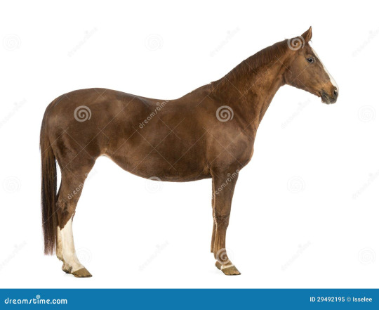
Make a reference image. Ideally you want a good head on front and side view of whatever it is you're making. I'm lazy and need a horse, so for this tutorial I'll be using this stock photo of a horse
Step 2:
Magic poser lets you group multiple objects together so they can be rotated and moved as a single shape, that is the only reason this method is any kind of doable. This step is technically optional but breaking the form down like this Before you start modeling makes it easier to organize things as you go, and breaks the task up into easier to digest components.
Your goal here is to break the form down into groups you will largely never ungroup. So large forms that will move as a single piece, things like legs and tails will generally be the exception and may be grouped and ungrouped repeatedly during the posing process.
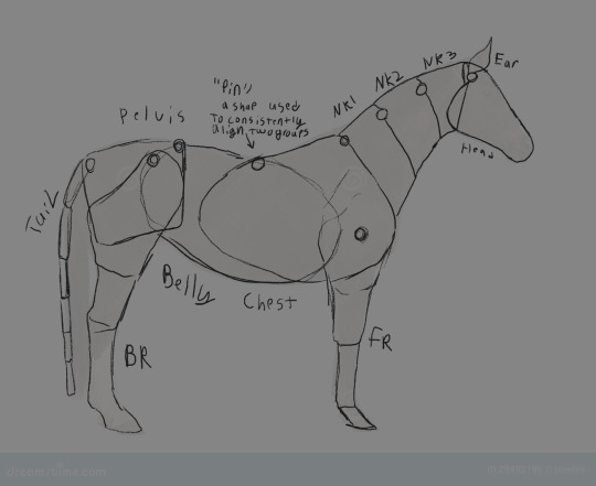
Because I'm going for a fairly high detail end result my groups will be:
Head
Nk1 (neck segment 1), Nk2, Nk3
Chest
Belly
Pelvis
FR1 (Front right shoulder), FR2 (Front right upper arm), FR3 (front right forearm), FR4(front right ankle),FR5 (front right hoof)
FL1, FL2, FL3, FL4, FL5
BL1, BL2, BL3, BL4 BL5
BR1, BR2, BR3, BR4, BR5
Step 2.2:
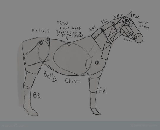
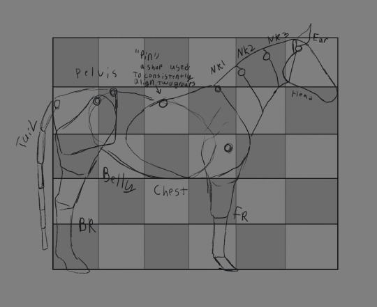
this is completely optional, but if you want to break up the groups into shapes ahead of time, that can make it easier to get everything set up in the file. Alternatively you can just create proportion blocks to give yourself easy reference points during the actual modeling.
Step 3:

If your model is going to interacting with another standard model then it can be helpful to drop the standard into the scene alongside any reference blocks you might have decided on in step 2.2, this is just so you don't have to resize the model every time you use it.
Step 4:
Good luck. (but for real, from here it's up to you to get everything sorted, there's not much specific advice I can give other than reminding you the fewer corners the better. and adding 'pins', a small pair of shapes used to line up two groups, is genuinely going to make your life so much easier. When you're done making a group it can also be helpful to set it to a default position, ungroup it, and then regroup it so it's axis of rotation is in a more convenient place)
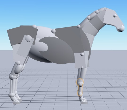
Step 5:
Use that grey fucker
24 notes
·
View notes
Text
FR4 thermal conductivity
FR4 Thermal Conductivity management for LEDs
Just like the light-emitting diode, which for decades served exclusively as an indicator lamp, PCB has also left its shadowy existence and has rapidly advanced to a multifunctional element within an electronic system. It, therefore, has to withstand high currents and ensure the cooling of high-clocked, but heat-producing processors and heat-dissipating power components, which brought us to today's topic- FR4 thermal conductivity.
1. Comparison of a conventional two-board solution with FR4 / copper combination
As UHB LEDs (Ultra High Brightness LEDs) with up to ten or more watts per housing and LED arrays with many LEDs placed closely next to each other are being used more and more, the question of heat dissipation is becoming more and more pressing.
This applies in particular since, unlike incandescent lamps, light-emitting diodes only emit a negligible part of the heat loss; practically everything goes the way of heat conduction.
Of course, there are solutions, for example, ceramic carriers or IMS PCB (insulated metal substrates) with thick aluminum cores. However, these are very expensive in comparison to classic FR4 PCB boards, and a second board is usually required to make to accommodate driver electronics.
FR4 PCB with copper wire
Moko Technology takes a different approach with »HSMtec«. The technology, which is qualified in accordance with DINEN60068-2-14 and JEDECA101-A and audited for aviation and automotive, is selective: only where high currents are supposed to flow through the printed circuit board does thick copper.
Currently, 500µm high profiles with widths from 2.0mm to are available in variable lengths, with wires a diameter of 500µm has become established. The solid copper elements that are firmly bonded to the conductor patterns can be applied directly to the base copper using ultrasound connection technology and integrated into any layer of a multilayer using FR4 base material. There are several reasons why copper is used: It has twice the thermal conductivity compared to aluminum and thus ensures rapid heat dissipation without insulating intermediate layers underneath the LED heat pad.
Table 1: Thermal conductivity of the materials involved Another advantage of copper and the circuit board base material FR4 are the thermal expansion properties (Table 2): Especially in connection with ceramic LEDs, circuit boards based on copper or FR4 have a high resistance to thermal stresses, which depend on environmental or operating conditions and others Temperature cycles, such as for "intelligent" lighting controls.
Table 2: Thermal expansion coefficient in the X / Y direction In this way, the lifespan and reliability of the entire lighting unit can be significantly increased compared to conventional metal core PCB based on aluminum.
Printed circuit boards manage heat
A look at the specific thermal conductivity shows the importance of the continuous metallic path from the source to the sink and the performance potential of HSMtec. Copper conducts heat 1000 times better than FR4. The combination of integrated copper profiles with modern circuit board constructions such as micro and thermovias makes it possible to directly contact a soldering surface (components, heat sink) to the profiles, thereby avoiding bottlenecks in the thermal path.
A thermally optimized layer structure also ensures rapid heat spreading and thus supports the entire thermal concept. In the case of very small LED housings, filled microvias ensure a direct metallic connection to heat-conducting copper elements, which can be attached approximately 60 μm below the top layer of the circuit board.
2. Thermal properties of metal core boards and FR4 thermal conductivity with embedded copper
Compared to Thermovias, which are placed directly under heat pads, for example, it is possible to solder filled microvias without any problems. Based on various empirical studies, Häusermann was able to gain all kinds of knowledge in the areas of thermal management and high current on the printed circuit board. The main advantage of HSMtec compared to alternative solutions is the use of inexpensive standard FR4 material in addition to manufacturing in the standard manufacturing process. It is also possible to use this process to construct self-supporting, multi-dimensional printed circuit boards with copper wire
With the help of notch milling at the predetermined bending points, individual segments can be brought into the desired orientation by any adjustment of the inclination angle. The thick copper integrated with profiles and wires withstands currents of up to 500 A. This represents a sensible alternative to circuit board solutions that provide full-area copper layers up to 500 µm thick, or to cost-intensive IMS solutions that use massive aluminum cores as heat carriers instead of the usual base material deploy.
The design allows large amounts of heat and/or high currents of up to 500A to be conducted directly inside the circuit board. In addition, the entire architecture does not require cables, connectors or other mechanical connections. This not only increases the reliability of the application but also its lifespan. In order to successfully implement creative lighting design with power LEDs, close cooperation between the customer and the circuit board manufacturer is essential: Already in the concept phase, the entire thermal design - from the printed circuit board to the luminaire housing - must be optimally coordinated. Different prototype variants and thermal analyzes allow individual solutions.
The properties and characteristics of FR4 thermal conductivity materials ensure great versatility at an affordable price. For this reason, they are often used to manufacture PCB boards. So it is not unusual for us to dedicate an article to them on our blog.
FR-4 is a standard set by the NEMA (National Electrical Manufacturers Association) for a composite of hardened epoxy resin and fiberglass fabric. The code 94V-0 is on all FR-4 circuit boards. It ensures that fire does not spread and goes out again quickly if the material catches fire. The glass transition temperature (Tg) for High TG or HiTG is between 115 and 200 ° C depending on the manufacturing method and the resins used. FR-4 uses bromine, a chemical element, and so-called refractory halogen. It replaces G-10, another composite material that is less fire-resistant in most applications. FR-4 also offers a good ratio between fire resistance and weight. FR-4 High CTI: The Comparative Tracking Index (tracking resistance) is over 600 volts. FR-4 without copper foil: Ideally suited for insulation boards, models and circuit board carriers. More information about the properties of these different materials can be found later in this article.
What holds our world together
The properties of base materials for electronic assemblies.
What is "base material"?
The individual components of the typical base material are adhesive, a backing material and the conductive layer. The FR4, the most widely used base material, is made of adhesive Epoxy resin and the base material made of twisted glass fibrils, which are woven into a glass fabricate. "FR" stands for "Flame Retarding" and thus points to the indispensable flame retardant Property of the material. The "4" stands for a certain FR type. There are also the types "FR2" and "FR3", which are hardly in use these days, and "FR5" with a higher one Temperature resistance as "FR4".
Prepregs and laminates
When manufacturing FR4 base material, the glass fabric with the epoxy resin is used first soaked. The result is "Prepregs", an artificial word that stands for "Preimpregnated" and on it to indicate that the epoxy resin matrix has dried but has not yet hardened.
Each prepreg consists of exactly one type of glass fabric, which is specified with a number, for example, "106", "1080", "2116" or "7628". This type of designation was previously related to the prepreg thickness is very binding. The 106 was about 50 µm thick, 1080 about 60 µm, 2116 approx. 115 and the 7628 approx. 180µm.
The modern demand for a safe but also inexpensive pressing of Multilayers has led to various prepreg variants that differ in the thickness of the resin coating differ. There are still prepregs with standard resin content but now also with medium ones and high resin content. The usual identifiers are then "SR" for "Standard resin", "MR" for "Medium resin" and "HR" for "High resin". Including all manufacturing tolerances, the thickness of one so-called 1080 prepregs recently between 56µm (= SR variant, lower tolerance) and 84 µm (= HR variant, upper tolerance) fluctuate.
Colloquially, "thin laminates" with thicknesses between 0.05mm and 0.86mm, and "Thick laminates" with thicknesses between 0.90mm and 3.2mm available. The thickness of the copper cladding can be 5, 9, 12, 17, 35, 70, 105, 210 or 420µm. There is no direct physical property associated with these copper thicknesses. The designations come from the Anglo-American language area for historical reasons just a multiple or an integer divisor of 1 ounce (= 35µm). Vincenz, Taube, Wiemers: PCB and assembly technology PCB and assembly technology. Prepregs and copper foils are the Electronics raw materials. laminates are already derived products. Incidentally, this reference also explains the classic PCB thickness of 1.50mm.
Technical characteristics of FR4 thermal conductivity
The foreseeable future belongs to the FR4 and its derivatives. The material is stable, the insulation is reliable, the dielectric behavior is usable, the costs are acceptable, the processing is established and the heat resistance is tolerable. The derivatives are essentially generated by modifying the epoxy resin matrix. In the wake of the switch to lead-free electronics (~ RoHS), it has become common to replace part of the resin volume with mineral fillers. This delays the temperature-related increased Z-axis expansion of the circuit board (parameter CTE (z) = "Coefficient of thermal expansion").
As a result of the higher temperature resistance, the likelihood that the circuit board will be damaged during soldering. One then speaks of “FR4 thermal conductivity with a higher Tg value” or also of “high Tg material”. The standard value for FR4 is 130 °, higher Tg values are 150 ° or 175 °, depending on the material manufacturer. In general, "Tg" is misleadingly translated as "glass transition temperature". What is meant, however, is that the epoxy resin structure becomes soft and elastic as soon as the Tg value is reached and that the Z-axis expansion consequently increases considerably.
Error events are then cracks in the contacted vias and/or tears of the internal conductor tracks from the via sleeves. Delaminations can also occur which leads to a partial dissolution of the pressed material composite. The consequence is usually a failure of the module. The continuous operating temperature of a module with FR4 material should not exceed 95 to 100 ° C. A higher Tg value does not increase the continuous operating temperature of a module. The continuous operating temperature essentially depends on the epoxy resin matrix and should not exceed 95 to 100 ° for FR4 material. Another parameter is the Td value. "Td" stands for "Time to Decomposition" and describes the temperature value at which the material has lost 5% of its mass due to outgassing/evaporation.
Since the introduction of SMD technology, the requirements for the base material have increased. The reduction in the design of SMD components also leads to a reduction in the SMD areas on the circuit board, because otherwise, reliable soldering is not possible (i.e. twisted components, tombstoning). When an SMD pad gets smaller, the area with which this pad adheres to the circuit board also becomes smaller. Simple mechanical loads, vibration and braking or acceleration forces can cause the component to tears. Reflow soldering additionally reduces the adhesion between the SMD pad and the circuit board by up to 75%, depending on the base material type, circuit board surface and number of reflow cycles. Unfortunately, the measures to achieve a high Tg in return often lead to a reduction in copper adhesion. With standard material, pull-off forces of around 2 N / mm can be found, which can drop to 0.8 N / mm with high-Tg material.
Note
Find out about the technical quality of base materials on the Internet or through a talk to your PCB manufacturer. Use the physical properties of Base materials for your circuit concept. Ensure that the used base material for consistently high product quality of your assembly.
0 notes