#ElectronicsKit
Explore tagged Tumblr posts
Visit Tumblr Blog
Explore Tumblr blogs with no restrictions, modern design and the best experience.
Last Seen Tumblr Blogs


Fun Fact
After the announcement of the deal with Yahoo!, there were 170K signatures of unhappy Tumblr users petitioning to prevent the sale in 2013.
Text
#ITEAD#ITEADTech#ITEADStudio#SmartTechnology#InnovationInTech#ElectronicsInnovation#SmartDevices#DIYElectronics#TechSolutions#MakerMovement#ElectronicsLovers#CreativeTechnology#TechCommunity#DIYProjects#SmartHomeTech#IoTDevices#TechForCreators#ElectronicsDesign#TechEngineering#ArduinoProjects#ElectronicsKit#RoboticsTech#TechHobbyist#InnovativeTech#MakerCulture#MicrocontrollerTech#TechGadgets#EmbeddedSystems#SmartTechSolutions#TechInspiration
0 notes
Text
💻 M55Stack Official Cardputer Kit with M5StampS3 - Perfect for DIY Projects! 💻
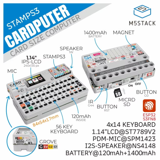
Unlock endless possibilities with the M55Stack Official Cardputer Kit featuring the M5StampS3! This versatile kit allows you to create your own custom electronics and computing projects. Ideal for makers, hobbyists, and engineers, the M55Stack Cardputer offers a compact, easy-to-use solution for building innovative devices. Whether you're learning about programming or creating your next tech project, this kit is a great choice for hands-on enthusiasts.
Special Offer: Price Now: $29.90
🔗 Click to Buy Now: M55Stack Cardputer Kit
#M55Stack#CardputerKit#DIYProjects#ElectronicsKit#TechDIY#M5StampS3#MakerCommunity#TechInnovation#ElectronicsEnthusiast#TechDeals#AliExpressDeals#Programming#Arduino#TechSale#GadgetLovers#CustomProjects#MakerMovement#EngineeringTools#AffordableTech
0 notes
Text
beep beep! new seesaw board tester kit coming thru! 🚚💨📦🔧🎛️💡🎚️🔋💻🔬🛠️💾🚀⏱️🏭🏎️💨
now that we can get chips we're churning out seesaw boards to help with all sorts of common needs - like this I2C to NeoPixel driver converter that uses an attiny816 . it's a 'no solder' way to add NeoPixel support since you can use the pre-attached terminal blocks. we've got our UPDI in-situ programmer running on a Metro M0 https://www.adafruit.com/product/3505 which can set the fuses and burn the firmware so fast, we have plenty of time to take a drive around the adafruit factory.
#Adafruit#SeesawBoardTester#ElectronicsKit#BeepBeepDelivery#NoSolderNeoPixel#I2CtoNeoPixel#ATTINY816#UPDIProgrammer#FirmwareBurning#AdafruitFactory#MetroM0#ElectronicsDIY#TechInnovation#AdafruitAVRProg#CircuitBoardMagic#FactoryTour#electronics#manufacturing#opensource#womanowned#nyc#technology
0 notes
Photo

⚡NEW VIDEO 🔊 Playing with the PhotoSynTheremin Kit by Citrus Circuits 🍊⚡ link in bio or right here👉 https://www.youtube.com/watch?v=9j5Y3KkDseU #diy #tech #electronics #hardware #circuit #electronicskit #citruscircuits #thecurrentsource #pcb #photosyntheremin #photodiode #theremin #synth #soldering #analog #make #makersgonnamake #makersmovement #nerdlife https://www.instagram.com/p/BtmkwaInr1-/?utm_source=ig_tumblr_share&igshid=140epuehtsfdr
#diy#tech#electronics#hardware#circuit#electronicskit#citruscircuits#thecurrentsource#pcb#photosyntheremin#photodiode#theremin#synth#soldering#analog#make#makersgonnamake#makersmovement#nerdlife
4 notes
·
View notes
Photo

Downloadable build instructions for the Warring Demons optical theremin are now available on my Etsy. More to follow #diy #sdiy #diysynth #synthdiy #noisemaker #theremin #noisemusic #avantgarde #experimentalmusic #diyelectronics #electronics #electronicskit #download (at Boston, Lincolnshire, United Kingdom) https://www.instagram.com/p/BsdepfshbdV/?utm_source=ig_tumblr_share&igshid=2kd2l1tmtgbg
#diy#sdiy#diysynth#synthdiy#noisemaker#theremin#noisemusic#avantgarde#experimentalmusic#diyelectronics#electronics#electronicskit#download
1 note
·
View note
Photo

Inforob is a STEAM based Education startup where we provide Different Curriculums and platforms both offline and online for different age groups (class 2 onwards). We regularly participate in international robotics competitions where we give chance to our kids to perform. Book slot now Visit : www.inforob.in Call : 91+ 9630456544 . . . . #electronics #visiting #dronetechnology #robotics #fly #drones #LearnByFun #exhibition #exploremore #electronicskit #Lego #competition #entrepreneur #education #design #simulation #assembling https://www.instagram.com/p/CKd4hATHqHc/?igshid=wt677lo3ud06
#electronics#visiting#dronetechnology#robotics#fly#drones#learnbyfun#exhibition#exploremore#electronicskit#lego#competition#entrepreneur#education#design#simulation#assembling
0 notes
Video
instagram
Great start of 2020! Reached 10K followers 😍 . . Thanks for your love and keep supporting us 🙏🏼 #innoboxlabs #smazee #startup #chennai #education #electronicskits #electronics #engineering #india ##10kfollowers #training #innoforum #innokit https://www.instagram.com/p/B7LHdP8pZOr/?igshid=11canp3uw5pva
#innoboxlabs#smazee#startup#chennai#education#electronicskits#electronics#engineering#india#10kfollowers#training#innoforum#innokit
0 notes
Video
youtube
Adjustable Voltage Regulator LM317 kit assembly video.
0 notes
Photo

2018-211: More Power - 2018-211: More Power - Gabe is learning about the joy of combining the power supplies of two kits in serial to get MORE POWER! RAWR! - https://flic.kr/p/29A2LZ7
0 notes
Photo

DIY Auto LCR Digital Electric Bridge Resistance Capacitance Inductance ESR Meter #eetkit #electronicskit #digitalkit #students #bridgekit #capacitance #inductance #arduinokit #arduino #electronics #eetparts #eetcomponents #components http://buff.ly/2uUDv74
#electronicskit#eetkit#eetparts#eetcomponents#digitalkit#capacitance#components#students#inductance#bridgekit#arduinokit#electronics#arduino
0 notes
Text
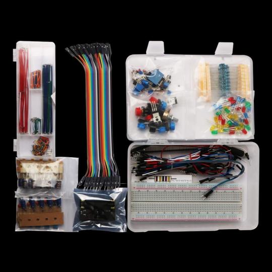
Keywish Electronics Component Super kit with Jumper wires,Color Led,Resistors,Register Card,Buzzer for Arduino
New Post has been published on https://devvee.com/product/keywish-electronics-component-super-kit-with-jumper-wirescolor-ledresistorsregister-cardbuzzer-for-arduino/ electronic, electronics kit, learning #Electronic, #ElectronicsKit, #Learning
Keywish Electronics Component Super kit with Jumper wires,Color Led,Resistors,Register Card,Buzzer for Arduino

Keywish Electronics Component Super kit with Jumper wires,Color Led,Resistors,Register Card,Buzzer for Arduino
Feature:
Keywishbot electronics component super kit perfect for anybody who wants to start Arduino, raspberry pi
Components List:
1 x Project Box
1 x Power Supply Module
1 x 830 Holes Breadboard
10 x Resistor(100Ω)
10 x Resistor(220Ω)
10 x Resistor(330Ω)
10 x Resistor(560Ω)
10 x Resistor(1k)
10 x Resistor(2k)
10 x Resistor(4.7k)
10 x Resistor(10k)
10 x Resistor(20k)
10 x Resistor(51k)
10 x Resistor(1M)
10 x Resistor(10M)
5 x 100uf Electrolytic Capacitors
5 x 100nf Metal Capacitors
5 x 100pf Ceramic Capacitors
5 x 47uf Electrolytic Capacitors
5 x 22uf Electrolytic Capacitors
5 x 330up Electrolytic Capacitors
5 x 100pf Monolithic Capacitor
10 x 1N4007 Diode
1 x Active Buzzer
1 x Passive Buzzer
3 x 10k Potentiometer
3 x 10k Potentiometer
1 x 10k Potentiometer
5 x Photosensitive resistor
5 x PNP Transistor (8550)
5 x NPN Transistor (8050)
2 x IRF520
2 x RGB LED
8 x Big Button
8 x Big Button Cap
2 x Read Pin Cap
2 x Blue Pin Cap
2 x Green Pin Cap
2 x Black Pin Cap
1 x 4N25
1 x SN74HC595
1 x JQC-3F(T73) 5VDC
10 x white LED
10 x Red LED
10 x Green LED
10 x Orange LED
10 x Blue LED
1 x 9V Battery Connection for Ardunio
1 x register card
1 x 90 degree 40Pin Header
1 x 40Pin Header
1 x 65 jmper wires
1 x 40 Pin connect wires
1 x 140 Pin breadboard jump wires
1 x Project Box


0 notes
Text
#ITEAD#ITEADTech#ITEADStudio#SmartTechnology#InnovationInTech#ElectronicsInnovation#SmartDevices#DIYElectronics#TechSolutions#MakerMovement#ElectronicsLovers#CreativeTechnology#TechCommunity#DIYProjects#SmartHomeTech#IoTDevices#TechForCreators#ElectronicsDesign#TechEngineering#ArduinoProjects#ElectronicsKit#RoboticsTech#TechHobbyist#InnovativeTech#MakerCulture#MicrocontrollerTech#TechGadgets#EmbeddedSystems#SmartTechSolutions#TechInspiration
0 notes
Text
HOW TO CONVERT INNOVATIVE CONCEPTS INTO A REALITY
Being an innovator since childhood has made me explore the various verticals of technology and got praised for my work for the quality of work and passion I invested in the development of those technical mini creations. With time, the demand for more aggressive technical innovations has emerged, to cope up with the ever-increasing demand of users. It is no more a moot topic that how technology really is helpful in offering the convenience in our lives.

We all yearn for technology, and the people like me are ever indulged in carving out the best possible ways to craft the technology so it can provide further comfort in our lives. But every technical innovation is not created without the required resources and getting the best quality DIY ElectronicsKits In India is something equivalent to boiling the ocean. For one of my recent Ultrasonic Sensor Arduino Project, I required a set of DIY gadgets but failed to find out the best option to serve my needs more systematically.
I discussed this issue with many innovators on different online forums, to be guided for the best portal, and out of 10 at least 7 suggested me only one name ‘Hobby and You’. At first, I was a little reluctant, but then I thought to give it a try and visited their website. For my utter surprise, the website was nothing less than a haven for innovators. The DIY Electronics Kits In India is of the best quality and is extremely affordable, to help you in solving the problem, practice skills, or do experiments, with switches, timers, receivers, transmitters, games, radios and many more possibilities which are endless. These DIY electronic kits consist of detailed assembly instructions, parts, and schematics.
With these DIY kits, you can learn and explore more about the electricity and it is fun and engaging to explore it further. Also, if you are looking for Ultrasonic Sensor Arduino Project, then ‘Hobby and You’ has the largest collection of in-stock electronics & Arduino products in one place to choose from. Indeed this portal is serving the needs of thousands of hobbyists, families, scouts, schools, universities, governments and corporations effortlessly and is expanding their wings to reach the wider audience.
I found ‘Hobby and You’ committed to low prices, personal customer service, quick delivery, and an easy & secure shopping experience. So you can get the best quality Ultrasonic Sensor Arduino Project and DIY Electronics Kits In India without shedding your sweat anymore.
I recommend ‘Hobby and You’ to every hobbyists, families, scouts, schools, universities, governments and corporation to try their services and believe me you would only experience the world-class customer service and the quality enriched products.
So what are you waiting for? Just visit their website http://www.hobbyandyou.com/ and experience the difference.
You can reach Hobby and You team at:
+91-9811680601
0 notes
Photo
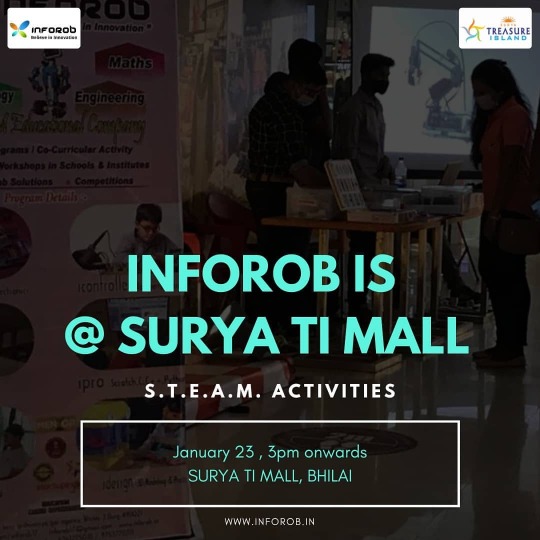
Tomorrow i.e. 23rd Jan 2021 INFOROB is at Surya TI Mall For STEAM Activities . . . . . #mall #exhibition #learnbyfun #visiting #explore #exploremore #lego #robotics #fly #drones #dronetechnology #electronics #electronicskit https://www.instagram.com/p/CKWF88in8GD/?igshid=1opsj9h95hf1s
#mall#exhibition#learnbyfun#visiting#explore#exploremore#lego#robotics#fly#drones#dronetechnology#electronics#electronicskit
0 notes
Photo

Tired But Wired . . . #wires #wiring #electronics #electronicskit #igdaily #instadaily
0 notes
Video
instagram
New electronica kit from Amazon I see station star this one is really nice it has lights it has music to it easy to put together and it’s very entertaining and simple nice soldering nice kit cheap I’m very happy #sa8die #mtf #trans #electronics #electronicskit #icstation #star https://www.instagram.com/p/CBpjFgpHBto/?igshid=12qbe1ndtrg4b
0 notes