#BJT bipolar junction transistors
Explore tagged Tumblr posts
Text
https://www.futureelectronics.com/p/semiconductors--discretes--transistors--bipolar-transistors/pmbta45-215-nexperia-9009695
Explore Bipolar (BJT) Transistors, Darlington Transistors, Digital Transistors
PMBTA45 Series 500 V 0.15 A 300 mW NPN SMT Small Signal Transistor - SOT-23
#Nexperia#PMBTA45#215#Transistors#Bipolar (BJT) Transistors#BJT bipolar junction transistors#IGBT transistors#Explore#Darlington Transistors#Digital Transistors#junction field effect transistor manufacturers#General Purpose
1 note
·
View note
Text
https://www.futureelectronics.com/p/semiconductors--discretes--transistors--bipolar-transistors/njvmjd31ct4g-onsemi-6177237
Switching applications, Bipolar transistor circuits, bipolar junction transistors
MJD31 Series 100 V 3 A 1.56 W Complementary Power Transistor - DPAK-3
#onsemi#NJVMJD31CT4G#Transistors#Bipolar (BJT) Transistors#Switching applications#Bipolar transistor circuits#bipolar junction transistors#Emergency lighting power supplies#NPN transistor#TV tuners#high voltage transistor#high frequency
1 note
·
View note
Text
https://www.futureelectronics.com/p/semiconductors--discretes--transistors--bipolar-transistors/mjd31ct4g-onsemi-6159837
Power supplies, Bipolar junction transistor, High voltage, Emergency lighting
MJD31 Series 100 V 3 A 1.56 W Complementary Power Transistor - DPAK-3
#Transistors#Bipolar (BJT) Transistors#MJD31CT4G#onsemi#power supplies#Bipolar junction transistor#High voltage#Emergency lighting#switch#Insulated gate#Voltage regulators#NPN#Switching applications#High voltage transistor
1 note
·
View note
Text
https://www.futureelectronics.com/p/semiconductors--discretes--transistors--bipolar-transistors/mjd31ct4g-onsemi-5834395
Power Transistor, High voltage transistor, insulated gate bipolar transistor
MJD31 Series 100 V 3 A 1.56 W Complementary Power Transistor - DPAK-3
#onsemi#MJD31CT4G#Transistors#Bipolar (BJT) Transistors#Power#High voltage#insulated gate bipolar transistor#bipolar junction transistor#Emergency lighting#transistor Digital signals#switching applications#switch
1 note
·
View note
Text
https://www.futureelectronics.com/p/semiconductors--discretes--transistors--bipolar-transistors/mjd31ct4g-onsemi-6159837
Surface Mount PNP Silicon Transistor, Emergency lighting, gate bipolar transistor
MJD31 Series 100 V 3 A 1.56 W Complementary Power Transistor - DPAK-3
#Transistors#Bipolar (BJT) Transistors#MJD31CT4G#onsemi#Surface Mount PNP Silicon Transistor#Emergency lighting#gate#Bipolar junction transistor#Switching applications#switch#Voltage regulators#NPN bipolar transistor#High voltage
1 note
·
View note
Text
https://www.futureelectronics.com/p/semiconductors--discretes--transistors--bipolar-transistors/mjd31ct4g-onsemi-1072659
NPN bipolar transistor, Insulated gate bipolar transistor, Voltage regulators
MJD31 Series 100 V 3 A 1.56 W Complementary Power Transistor - DPAK-3
#Transistors#Bipolar (BJT) Transistors#MJD31CT4G#onsemi#NPN#Insulated gate#High voltage transistor#Transistor switch#Bipolar junction transistor#Emergency lighting#Switching applications
1 note
·
View note
Text
https://www.futureelectronics.com/p/semiconductors--discretes--transistors--bipolar-transistors/smmbta06lt1g-onsemi-8097919
What is transistor, Power transistor, Switching loads, Emergency lighting
MMBTA06L Series NPN 80 V 500 mA SMT Driver Transistor - SOT-23
#Onsemi#MMBTA06LT1G#Transistors Bipolar (BJT) Transistors#Power#switching loads#Emergency lighting#High voltage#insulated gate#switching application#Voltage regulators#switch#junction#Digital signals
1 note
·
View note
Text
https://www.futureelectronics.com/p/semiconductors--discretes--transistors--bipolar-transistors/mmbta06lt1g-onsemi-9159854
Surface Mount NPN Silicon Transistor, Driver Transistor, what is transistor
MMBTA06L Series NPN 80 V 500 mA SMT Driver Transistor - SOT-23
#Transistors Bipolar (BJT) Transistors#MMBTA06LT1G#Onsemi#Surface Mount NPN Silicon Transistor#Driver Transistor#Emergency lighting#bipolar junction transistor#insulated gate#NPN Silicon Transistor#circuits#High voltage transistor
1 note
·
View note
Text
https://www.futureelectronics.com/p/semiconductors--discretes--transistors--bipolar-transistors/mmbta06lt1g-onsemi-7421506
Onsemi, MMBTA06LT1G, Transistors, Bipolar (BJT) Transistors
MMBTA06L Series NPN 80 V 500 mA SMT Driver Transistor - SOT-23
#Onsemi#MMBTA06LT1G#Transistors#Bipolar (BJT) Transistors#High voltage transistor#High power transistor#NPN transistors#Bipolar junction transistor#emergency lighting#NPN#transistors manufacturers#circuit
1 note
·
View note
Text
NPN/PNP Digital Transistor, transistor switch, Bipolar junction transistor
PUMH9 Series 50 V 100 mA Surface Mount NPN Small Signal Transistor - SOT-363
#Transistors#Bipolar (BJT) Transistors#PUMH9#115#Nexperia#NPN/PNP Digital Transistor#transistor switch#Bipolar junction transistor#manufacturers#NPN Small Signal Transistor#circuits#gate#high voltage transistor
1 note
·
View note
Text
What is bipolar transistor, bipolar junction transistor, high voltage transistor
PUMH9 Series 50 V 100 mA Surface Mount NPN Small Signal Transistor - SOT-363
#Nexperia#PUMH9#115#Transistors#Bipolar (BJT) Transistors#bipolar junction transistor#high voltage transistor#Power Transistor#High Safe Operating Area#Emergency lighting#regulators#High DC Current Gain#NPN#Insulated gate bipolar transistor
1 note
·
View note
Text
What is a bipolar transistor, transistor manufacturers, high voltage transistor
PMBTA45 Series 500 V 0.15 A 300 mW NPN SMT Small Signal Transistor - SOT-23
#Nexperia#PMBTA45#215#Transistors#Bipolar (BJT) Transistors#what is a bipolar transistor#manufacturers#high voltage transistor#Medium Power Transistor#insulated gate bipolar transistor#switch#npn transistor#bipolar junction transistor
1 note
·
View note
Text
How does the DC-DC converter work?
DIY voltage-boosting LED driver
How is it assembled? How do you convert an existing one to suit your needs?
Hi! My secret helper wrote this post.
She's in love with electronics, guitars, and cats.
Kevin (teardownit.com editor)

ANOTHER secret helper. This guy can't write posts.
We will consider the principles of how a step-up (boost) converter operates, and most importantly, current and voltage feedback, using a homemade LED flashlight as an example.
Pulse power converters (or voltage converters, as they are generally called) have long been an integral part of electronic technology. The fact of the matter is, chemical current sources such as batteries and accumulators produce low voltage, while many other devices, primarily those based on vacuum and gas-discharge lamps, require high voltage.
The basis for today's DIY kit is the ready-made ICSK034A from icstation.com. This is a kit for assembling a 5 to 12 volt step-up converter.

This isn’t just a joule thief, but a stabilized converter that maintains a predetermined voltage at the output. However, my goal today is not to make a 12V power supply, instead, I want to make an LED flashlight with continuously variable brightness. In other words, I’m going to make a controlled boost current regulator for the LED.
So, today we are going to study the feedback of pulse power converters and as a result, we will be able to build a converter with the properties that we need. Or we can modify an existing converter to the one we need, specifically, one where we can add or change the current or voltage feedback. Or we can make the existing feedback controllable, i.e. add the possibility of reconfiguration.
The main component of a step-up converter is the coil. In electronics, coils and capacitors are called reactors because there is a reaction, i.e., a counteraction.
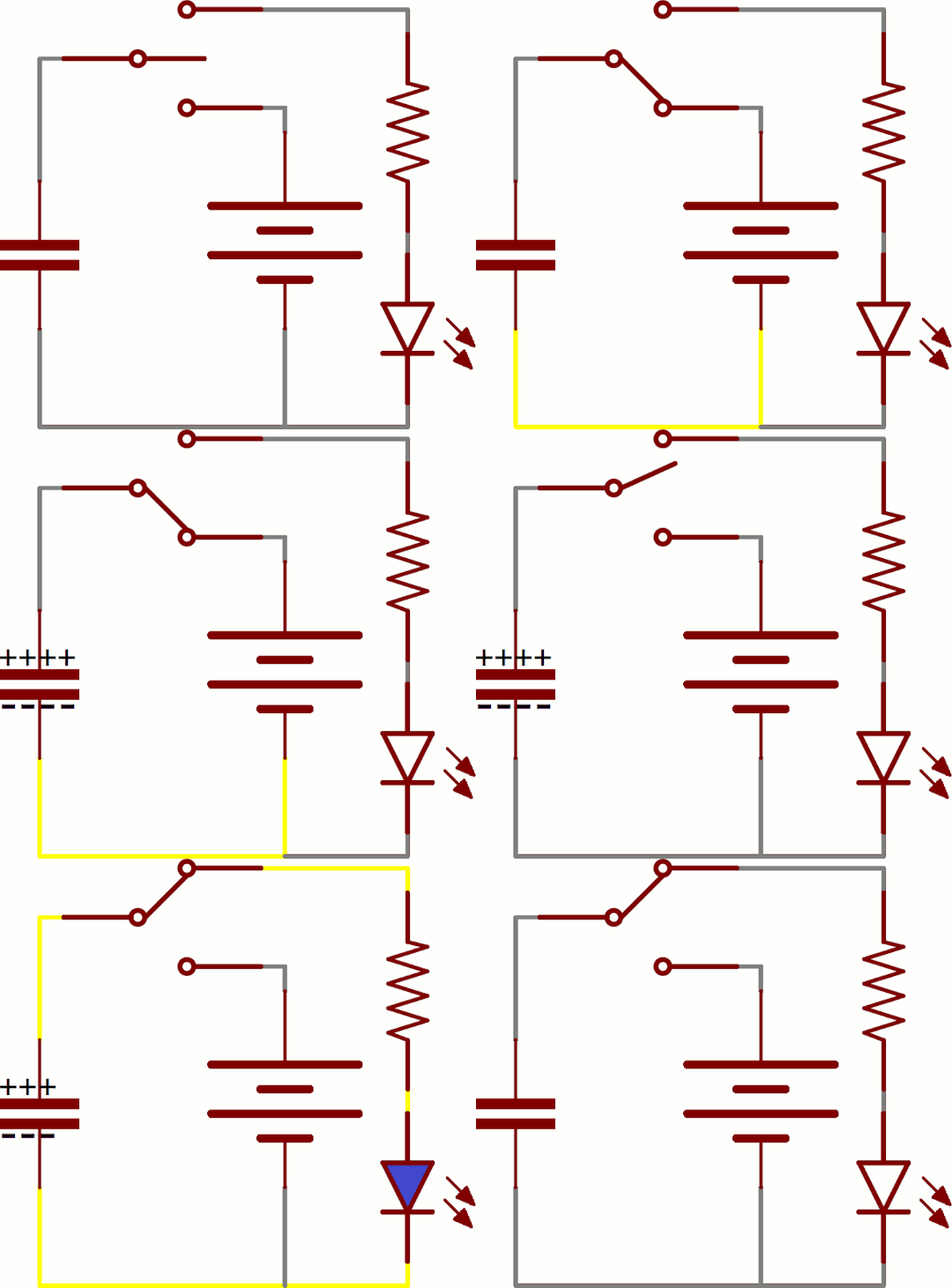
Converter operating principle
The step-up voltage converter works as follows. The power consumer is connected to the power supply through a coil and a diode. If nothing happens, the voltage at the consumer is equal to the input voltage minus the drop on the diode and the coil's active resistance.
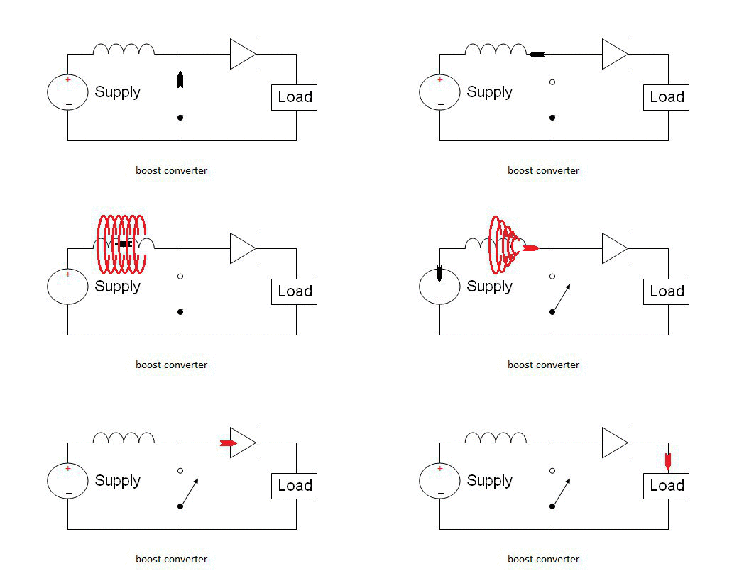
But after the coil, there is a switch that closes the circuit, which consists of the power supply and the coil. In a real converter, this would be a bipolar junction transistor (BJT) or a field-effect transistor (FET). This can also be a separate transistor or one that’s integrated into a chip.
When this switch closes the circuit, the current in the coil increases. The active resistance of the coil is usually low, so it should be turned on briefly so as not to burn anything out.
When the switch breaks the circuit, the coil tries to keep the current constant. Now there is no path for the current to take through the switch, so it will go through the diode to the power consumer instead.
When the circuit of the switch is opened, the current decreases. At the moment the current decreases, an electromotive force (EMF), i.e. voltage, is generated in the coil. Its polarity causes the current to flow in the same direction as it did when the switch was turned on.
That is, this additional voltage is added to the EMF of the power source. Therefore, the power consumer receives more voltage than the original source provides. This is the reason why this type of converter is called a “boost” converter.
The capacitor smoothes out voltage spikes in parallel to the power consumer. When the coil generates an electromotive force, it is charged to a higher voltage. When the coil is charged with current through a switch, the capacitor gives the stored charge to the power consumer.
These two reactors, or integrators, the coil, and the capacitor are integral parts of the step-up conversion process and are mandatory components of the converter.
A diode is also mandatory, as it prevents the capacitor from discharging through the switch. The diode only allows the current to flow in one direction. If the power consumer is a battery, the diode prevents it from discharging through the switch.
Properties of the inductor coil
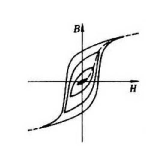
The voltage at the output of the inverter depends on the discharging capacitor’s current consumption and its charging energy given by the coil in each duty cycle. The magnetic field energy of the coil with current is equal to the inductance of the coil multiplied by the square of the current in it.
For its part, the strength of the current running through the coil depends on the voltage of the original source and the time during which it was charged. This is because as magnetic energy accumulates, the current strength increases gradually in the coil.
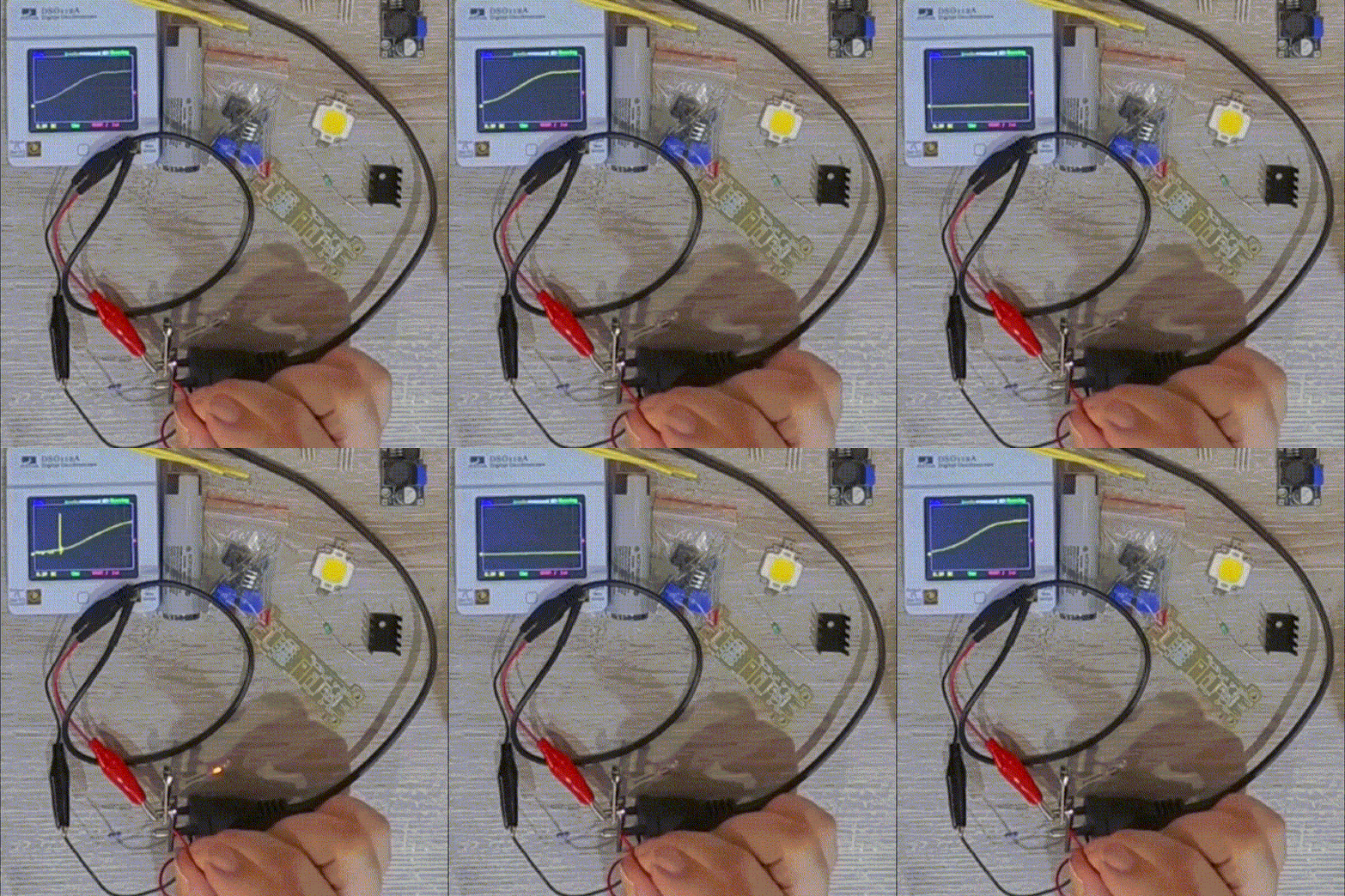
We can observe that the current gradually increases. The oscilloscope shows the voltage on the series resistor, which depends on the current as per Ohm's law.
A resistor that converts current to voltage for the purpose of measuring the current or current feedback is called a shunt.
We can observe a beautiful exponential fragment of the magnetization curve because the coil is charged with current just like a capacitor is charged with voltage. When we break the circuit, we can observe the neon bulb light up.
It needs at least 50 volts to break through the interelectrode gap and establish a glow discharge. It’s even closer to 80 volts. The battery voltage is 3 volts. You can observe how the coil’s voltage increases by several orders of magnitude.
Study the diagram
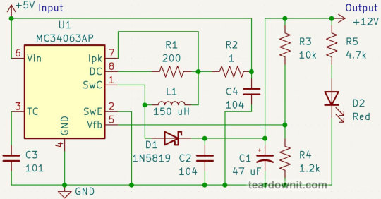
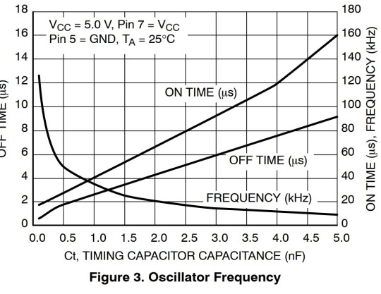
Now let's look at the circuit of the converter. It is built on the MC34063 chip. The capacitor C3 determines the frequency of the oscillation. The capacity of 100 picofarads corresponds to the highest frequency of this chip, which is 100 kilohertz. That is 100,000 on-and-off actions per second. Our electronic friends sure know how to work fast.
The resistor R2 determines the peak current of the output transistor, i.e. our switch. It is a shunt. When the voltage on it reaches 300 millivolts, the chip closes the transistor, thus stopping the further increase of current. 300 millivolts on a 1 Ω resistor will be at 300 milliamps current.
The resistor R1 limits the base current of the output transistor. It is not a shunt because this resistor does not turn the current into a voltage that controls anything, but simply limits the current according to Ohm's law.

The small LED D2 has two functions. It is both an indicator of the instrument’s operation and most importantly, the idle load.
An idle load is a mandatory part of any inverter or stabilizer since neither can operate when no power is being consumed because there would be nothing to convert or stabilize.
Now for the best part. Any stabilizer has a feedback input. The stabilizer controls the movement of something, such as an electric current, in such a way that the feedback voltage always equals a certain value.
The linear voltage regulator opens the output transistor so that the voltage between the output and the feedback pin is 5 volts if it is a 7805, or 1.25 V in the case of an LM317.
All excess voltage falls on the line stabilizer transistor. This transistor is connected in series with the power consumer. Therefore the current through them is the same.

Let’s say that it’s one ampere, for example. The power supply voltage is 9 V, and the power consumer voltage is 5 V. That is a four-volt drop on the transistor.
Power is equal to current multiplied by voltage. Therefore, the total consumption from the power supply would be 9 watts. But the consumer only gets 5 of these watts. Four watts are lost on the stabilizer transistor, which heats it.
This is a waste of energy, which is especially bad in conditions of autonomous power supply from batteries or generators. The line stabilizer also needs a heat sink to cool it, which comes with additional volume, weight, and cost.
Unlike a linear converter, a pulse converter opens and closes the output transistor completely. When the transistor is fully open, there is a small voltage drop across the transistor, so less heat is generated. The pulse converter has the capability of increasing the voltage, while the linear converter can only decrease it.
So, the feedback input of this pulse chip is its fifth pin. The MC34063 controls the duty cycle so that it holds 1.25 volts on the feedback pin.
The duty cycle is the ratio of the time interval when the transistor is open to the total period of oscillation.

In the schematic, the voltage divider R3R4 is connected to the feedback pin. The resistor R4 has a resistance of 1.2 kΩ. The voltage across it is nearly 1.2 volts, so the current will be one milliampere.
Therefore, the resistor R3, with a resistance of 10 kΩ, will have a voltage of 10 V. 10 + 1.2 = 11.2, that is, almost 12 V at the output of the inverter. This is the voltage feedback.
To get the current feedback, you need a shunt the voltage of which is 1.25V at the desired current. The kit page on the developer's website, http://www.icstation.com/icstation-step-module-boost-converter-power-supply-module-p-4151.html, says that the converter can handle 60 milliamps at five volts on the input and 12 volts on the output.
I plan to use an LED matrix with an operating voltage of about 10 volts. This matrix consists of three white LEDs connected in series. It turns out that the output voltage of the converter will be the same: 10V at the LED plus 1.25V at the shunt.
However, I won’t be powering the converter from a five-volt USB power bank, but rather from a lithium battery. Its minimum voltage is 3.7 V.
The lower the input voltage is, the higher the load on the coil and the transistor of the step-up converter.
The chip in this kit is quite powerful, but the coil is weak. Therefore, it is possible to draw a current of (60/5)*3.7 = 44 milliamps from the output of the inverter. Hence, the shunt resistance should be 30 Ω.

This huge LED can draw up to 900 mA, but it needs a heat sink in this case. If I were to use a more powerful coil, it would be possible to make a step-up converter with a higher output current.
Accordingly, I could set a higher peak current with the resistor R2, but not more than 1.5 amperes, because this is the limit for our chip.
I also want to add gradual brightness control. To this end, I won’t connect the shunt directly to the feedback input, but with a 1.2 kΩ resistor. The feedback input of the chip has a high resistance, so this resistor will not change anything on its own.

We’ll add a 50 kΩ variable resistor and a 5 kΩ ordinary resistor in series to prevent a direct connection of the feedback pin to the inverter output.
Now the feedback voltage will be equal to the sum of the shunt voltage and the additional 1.2 kΩ resistor. The chip keeps the feedback voltage constant. It will always be at 1.25 volts.
Therefore the voltage at the shunt, and therefore the LED current, will be lower by the value of the voltage at the additional resistor. This voltage depends on the current running through the variable resistor.
If this current value is one milliampere, the shunt is left with zero volts in total. In other words, the LED is not powered.
Everyone, or at least nearly everyone, knows that LEDs are powered by current; the higher the current, the brighter the light. At the same time, the voltage of the LED remains practically constant at different current values.
Sometimes LEDs are even used as stabilizers, i.e. voltage regulators. Thus, we’ll consider that the voltage across these three resistors (50k, 5k, and 1.2k) is ten volts.
If the variable resistor knob is in the 0 Ω position, the resistance of this circuit is 6.2 kΩ. The current is above 1 milliampere, that is, the LED is off.
If the knob is in the 50 kΩ position, the total resistance is 56 kΩ and the current is 180 microamperes.
This is eighteen percent of one milliampere. Therefore, the shunt resistance can be reduced by eighteen percent. So we get 26 Ω for the shunt.
As a result, we get a brightness controller. If the LED is always connected to the output of the inverter, nothing else needed to be done. The LED will limit the output voltage of the inverter.
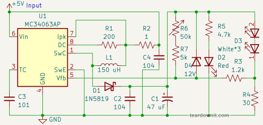
If there’s no LED or the output voltage is lower than the operating voltage of the LED, that is, it is closed and does not take part in the operation of the circuit, the brightness control circuit operates as voltage feedback.
The current of the divider is one milliampere. Specifically, the number of volts at the output is equal to the number of kΩ of the total resistance of the divider. The lowest voltage output is 6.2 volts. This is acceptable.
However, the highest voltage is 56 volts, which is too high. This can damage the electrolytic capacitor and the diode.
What can we do with the voltage feedback so that it doesn't interfere with the brightness controller? A Zener diode can save the day. This is a special diode that is connected in the reverse direction.
If the voltage on it is lower than its operating voltage, it stays closed and does nothing. If the voltage reaches the operating voltage, it opens and stabilizes the voltage.

In other words, when the LED is plugged in, the Zener diode doesn’t interfere with the flashlight’s operation. When the LED is not connected, the output voltage will be 12 + 1.25 = 13.25V. This voltage may be lower, depending on the position of the brightness control.
Now we can assemble the inverter with the circuit modifications that we have now developed.
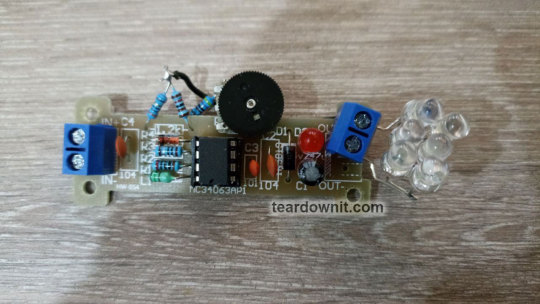
The 900-milliampere matrix refused to work from the converter. It needs at least 200-300 mA. The matrix just eats up the small current and doesn’t even glow.
Therefore, I made a matrix of 2p3s (two in parallel, three in series) from ordinary 5mm white LEDs. Thus, the allowable current is 2*20 = 40 mA and the operating voltage is 3*3.3 = 10 V. I didn’t decrease the shunt resistance to 26 Ω, but left it at 30. Moreover, I had just the right resistor in stock.
The video shows tests of the resulting driver at different supply voltages. The brightness adjusts perfectly. The boost converter actually starts working at 1.75 volts of the input supply which is much sooner than at the 3 volts that the chip datasheet proclaims.
With an input voltage of 1.8 V, there’s already enough voltage at the output for the LED matrix to start glowing.
To measure the power conversion efficiency, I connected voltmeters and ammeters to the input and output. The results can be observed in the following table, which shows the measurements at different input voltages and brightness control positions.

The abundance of information can look intimidating, especially in its raw form. However, we only need to look at the columns that display the input voltage, output power, and efficiency. Electrical power is equal to the product of voltage and current, while efficiency is the ratio of output power to input power.

This is a graph that shows efficiency vs. input voltage. It’s much more comprehensible than the table. The graph shows that the converter works more efficiently when the supply voltage is higher than 3.5 volts. We can also see the smooth lines corresponding to the turns of the LED brightness control knob, i.e. the output current of the converter.

And this is a graph of efficiency vs. output power. Judging from this, we can say that in the case of our flashlight, the higher the power, the more efficient the conversion is. Again, we see smooth lines, but this time they’re "drawn" by turning the supply voltage regulator.
Why is the efficiency of our flashlight so low? First of all, the shunt loses as much as 1.25 volts. This is more than 12 percent of the LED matrix’s voltage, so it’s more than 12 percent of the efficiency.
Secondly, the supply current of the red indicator LED is comparable to the current of the matrix. At the same time, this indicator is not powered by the input, but by the output. Its current draw resistor R5 simply converts part of the power consumption into heat.
Furthermore, the voltage drops on the Schottky diode D1 and the output power switch that’s built into the MC34063 chip. This switch is a bipolar transistor.
If we were to use a more modern DC-DC converter chip with a MOSFET transistor as an output switch, a lower feedback voltage, and correspondingly, lower shunt losses, the efficiency of the flashlight would be much higher.
DC-DC converters with a synchronous converter that uses a MOSFET instead of a Schottky diode are even more advanced than that.
Alternatively, we could add a shunt signal amplifier, or reduce its resistance and shift up the bias range from the brightness regulator. For example, this could be done in such a way that at maximum LED current, 0.25 volt falls on the shunt and 1 volt comes from the regulator, then the brightness is at its maximum, up to 1.25, then the LED doesn’t shine at all.
Conclusion
In conclusion, today we found out that the world of DC-DC converters is diverse and complex, but it is possible to achieve the desired result through simple means.
To do this, it’s enough to understand how feedback works and how to form the feedback voltage.
A shunt can be used to convert the output current to voltage and, as a result, get a current regulator. The output voltage can be stabilized with an output voltage divider. The output voltage can be limited by a Zener diode, without interfering with the current regulator. With a bias current through a variable resistor, it’s possible to add the desired value to the feedback voltage, making the current regulator adjustable.
Thank you for your attention!
Demo video
youtube
2 notes
·
View notes
Text
Study tips & tricks to follow before ASVAB Test
ASVAB TEST PREP : JOIN US AT PRIVATE STUDY GROUP 👈.
Use the Process of Elimination If unsure of an answer, eliminate obviously incorrect choices to improve your odds of guessing correctly. Skip tough questions and return to them if time permits. Don’t spend too much time on a single question. Move on and come back later if necessary. Take ASVAB practice tests 👈 to identify weak spots.

Here are some important question those have been encountered in ASVAB Test:
Which type of diode is used for voltage regulation?
a) Zener diode b) Light-emitting diode (LED) c) Schottky diode d) Rectifier diode
Answer: a) Zener diode
What is the main use of a Bipolar Junction Transistor (BJT)?
a) As a rectifier b) As a switch or amplifier c) As a capacitor d) As a resistor
Answer: b) As a switch or amplifier
Which of the following transistors is current-controlled?
a) Field-effect transistor (FET) b) Bipolar junction transistor (BJT) c) Metal-oxide-semiconductor FET (MOSFET) d) Junction field-effect transistor (JFET)
Answer: b) Bipolar junction transistor (BJT)
JOIN US AT ASVAB TUTORING TO GET STUDY MATRIALS AND RESOURCES.
#carrier aviation#military#us army#air force#us marines#navy#royal navy#us navy#marine biology#helicopter#asvab online courses#asvab test prep#asvab study tips#asvab online classes#asvab prep#asvab test
1 note
·
View note
Text
Introduction to the 2N3904 Transistor
Introduction to the 2N3904 Transistor
The 2N3904 is a widely used NPN bipolar junction transistor (BJT), typically employed for low-power amplification and switching applications. It’s part of the 2N3900 series and is known for its reliability and versatility. The transistor can handle voltages up to 40V and currents up to 200mA, making it suitable for a range of low-power electronics. Its small size and low cost contribute to its widespread use in various circuits, such as signal amplification, audio devices, and logic circuits.
Key Features of the 2N3904 Transistor
The 2N3904 transistor is characterized by a moderate current gain (hFE), typically between 100 to 300. It has a maximum collector-emitter voltage of 40V and a maximum collector current of 200mA. With a transition frequency of 250MHz, it offers efficient switching and amplification at higher frequencies. Its compact TO-92 package ensures easy integration into circuits. These features make it ideal for general-purpose applications, from small signal amplification to switching tasks.
Applications of the 2N3904 Transistor
The 2N3904 is widely utilized in signal processing applications, including audio amplification and low-frequency oscillators. It’s commonly found in electronic devices like radios, audio amplifiers, and switching circuits. In digital circuits, the 2N3904 is often used for logic level switching, signal conditioning, and timing circuits. Its small size and versatility allow it to be used in various consumer electronics, automation systems, and hobbyist projects, where moderate power handling and reliability are needed.
How the 2N3904 Transistor Works
As an NPN transistor, the 2N3904 operates by allowing current to flow from the collector to the emitter when a small current is applied to the base. This small current acts as a switch, controlling the larger current between the collector and emitter. When the base-emitter junction is forward biased (positive base), the transistor turns "on," allowing current to pass through the collector-emitter path. When the base-emitter junction is reverse biased (negative base), the transistor is "off," blocking current flow.
Advantages and Limitations of the 2N3904 Transistor
The 2N3904 is popular for its cost-effectiveness, compact size, and ease of use in low-power circuits. It offers good performance in many applications, especially in audio and signal processing. However, its current handling capacity is limited to 200mA, making it unsuitable for high-power applications. Additionally, its voltage and current limitations can restrict its use in more demanding systems. Despite these limitations, its widespread availability and versatility in low-power applications make it a go-to choice for many electronics enthusiasts and engineers.
0 notes
Text
Experiment - 2
Aim : Study of characteristics of an n-p-n bipolar junction transistor (BJT). Electronic Parts Required : (i) Power supply, 2 Nos : 0 ~ 15 V (ii) RB , RC = 1.0 KΩ , 2 Nos (iii) RB , = 220 Ω , 1 Nos (iv) 1.0 kΩ Potentio-meter, 1.0 W (v) NPN Transistor = 1 No , CL 100 / SL 100 [CK 100 / SK 100 = PNP (equivalent) transistors] (vi) Breadboard = 1 No (vii) Two DT-830D multi-meters for current…
0 notes