Don't wanna be here? Send us removal request.
Photo
‘WithAnimating with a target for avatars and Animesh for Second Life, Blender 2.9, Avastar 2.81.38 This is rough and I hope to find a better way to do this, or more flexible techniques.
Step 1
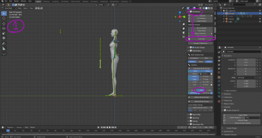
After adding initial avatar, add second Avastar armature, Skeleton Only. Under the N-menues, Avastar, Workflow, activate Joint Edit and move any desired bones (The tail bones here) to the general location. Rig Display can be used to turn off/on visibility of bones. Both armatures will have to share the same origin position or the uploaded mesh will be offset by the difference when uploaded.
Step 2
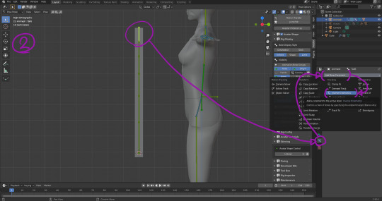
Created basic lengthened cube, cut into as many sections as required (It will bend and wiggle). On the final control bone, go to Bone Constraints and give it an Inverse Kinematics, Chain length 6 (its entire length), Stretch on, Use Tail. We will be returning here later.
Also bind said cube to the tail bones by selecting the cube, then the armature, and going to Avastar -> Rigging -> Bind to Armature. Automatic from Bones if we don’t need fancy weight-painting. (Note to self: To paint ‘through’ the mesh when Weight painting, preferably use the drop-downs at the top instead of the N-menu. Brush -> Front Faces Only to Off, Falloff -> Projected and Front Face Falloff to Off.)
Step 3
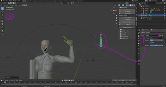
Create curve for target path. Create Armature of 1 bone as the target. Select bone, go into Pose mode, select the single bone, and in bone Bone Constraints, give it Clamp To, with the freshly-created curve as the Target. Main Axis: Auto means it’ll go along its longest path. Now when you move the bone around in pose mode it will stick to the path like a magnet. Note that the path itself can be parented to the shoulder or body to create a moving path for the target that inherits the torso’s rotations, etc.. Caveat: I believe certain Bone Constraints such as Copy Rotation do not work off of animated/posed positions, only object/edit mode positions so for those, it cannot be dynamic. Inverse Kinematics with Rotation Influence turned on will work for that purpose if required.
Step 4
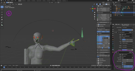
Give the fingertip a 6-length Inverse Kinematics Bone Constraint targeted at the path bone. These green bones are Avastar control bones and do not correspond to actual SL bones so the can be given constraints pretty freely.
Step 5
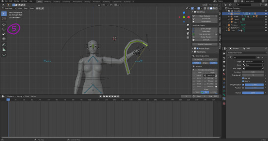
Give the tip of the Tail bone’s Inverse Kinematics the path bone as its target. If the tail is too far from the target, it will go taut as it reaches for it in a straight line. Move it closer to get a curve. Both Arm and Cube now track the target as it moves along the path. Open the Dope Sheet (Its a panel), select the armature and add keyframes at its starting and stopping point. Being a simple test, I just moved it back and forth in 20 frames. Repeat the same for the tail bones moving the cube.
Step 6
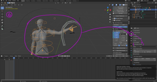
Almost done. Select avatar armature, go to Render Properties and export the first animation. I’ve been told the BVH format is legacy which explains why uploaded BVH files are jerky and seem to be very ‘lossy’ (jerky) so never use it. Select the tail and export the second animation but turn on “With Bone Translation” for that one since we have edited joints and moved it way off its original position. Also set lengths of animations, and loop.
Finally export the wiggle cube itself using default avastar export options. When uploading to SL, include both “weights” and “joints”. Attach wiggle cube to self (Origin) and give it a basic llStartObjectAnimation to animate it. Both your own and the object’s animation will have to be synchronized in LSL.
0 notes
Photo
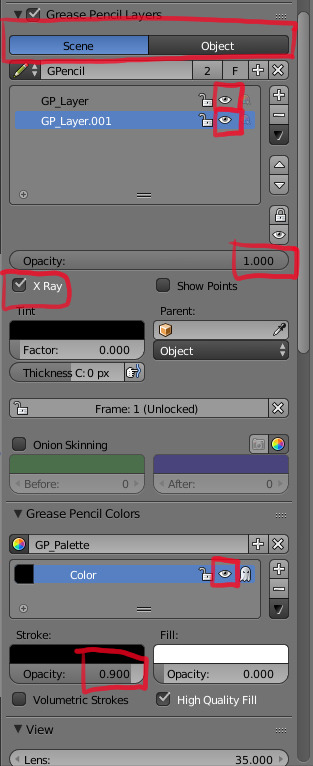
The many ways to accidentally hide the grease pencil layer and waste time trying to get it back later -_-
0 notes
Photo
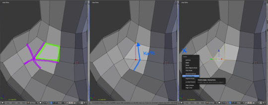
This polygon is stretched! Usually when its a 5-pointed star.
Knife tool it and delete the extra edge~
0 notes
Photo
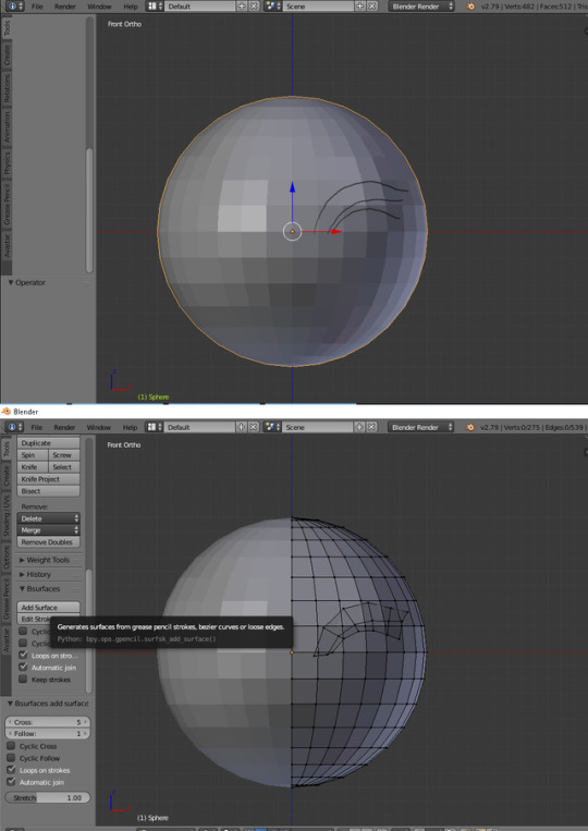
1. Go to User Preferences, search for BSurfaces, Turn it On, Save User Preferences.
2.Grease Pencil Settings, Data Source -> Object, Stroke Placement -> Surface
3. Draw your Edge Flows (Diagram A)
4. Edit mode, Tools. Bsurfaces -> Add Surface. Keep Strokes keeps and converts the grease pencil you used into a bezier curve with a million control points.
5. Fiddle with further settings at lower left. Cross makes curves smoother (more segments). Follow makes it ‘thicker’. Cyclic Cross connects the sides to form a tube (Good for hair, roots, branches, etc. Cables if your drawing is precise-enough). Cyclic Follow connects the ends to form a ring.
If using Cyclic Follow recommend you do not draw closed circles (leave a little gap) and use Automatic Join instead, otherwise it will result in an odd twist or overlap at the ends.
Further news as events develop.
0 notes
Text
Welding normals
To make 2 objects in blender look like a single seamless object (Necessary for connecting multiple meshes together)
Turn on Autosmooth, set angle appropriately (probably 180)
Might have to clear Custom Normal Data.
Add Data Transfer modifier. Set source object as adjacent object.
Face Corner Data, Yes
Custom Normals, Yes
Set Max Distance, minimal (Need to click little button next to the field first)
Source from
https://avastar.online/knowledge/welding-normals/
0 notes
Photo
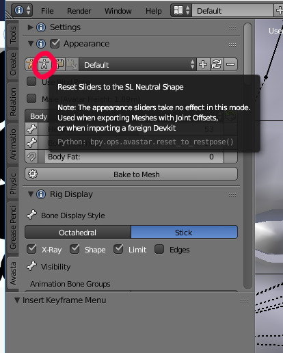
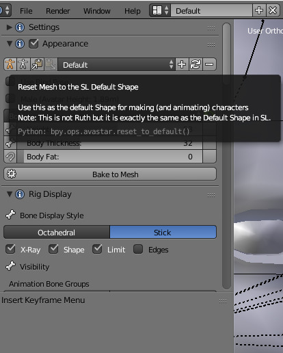
Big Note: If making rigged meshes with translated/moved bones (i.e. using Joint Offsets), it is very important to set the appearance sliders to Neutral Shape before starting (Image 1). This seems to be the base shape SL itself uses as a reference/starting point, NOT the Default Shape. Anything built upon the body and rigged with the Default Shape sliders will be offset and shifted once imported into SL, even if you’re wearing a Default Shape. Once in Neutral Shape mode, appearance sliders will no longer affect the SL starting body mesh that is in Blender that comes with Add -> Avastar -> Extended.
Avastar defaults to Default shape (Image 2)
Now to go listen to Bonetrousle for several hours -_-
0 notes
Text
Rigging wires and other things attached at 2 points
Anchoring on two points will require a Targetless IK on the tail end of the Armature. Create a dummy bone and have it be an attachment point. Parent the attachment point bone to the desired bone on the main armature that it will ‘follow’. The Targetless IK is that given that Attachment Point armature as a Target. Maybe.
0 notes
Text
Note to self
Note 1: Edit mode
Armature -> Bone Roll -> Recalculate Roll -> Global +Z
Because eyelid bones rotate funny.
Note 2: Vertex weight mix mode to move bone weights from one vertex group to another. Applies from group B onto group A. Mix Set is literally in terms of Sets (like boolean operator) to determine which vertices of the two groups that are to be affected.
1 note
·
View note
Text
Texture-painted Displacement Map to Normal Map Export Bake for Second Life use
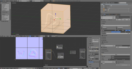
Experiment successful.
Need Cycles Render nodes.
Cube created, given UV-map, given a texture. The texture is then painted on with Blender Texture Paint, its Color output piped into a Normal Map, which is then Piped into Displacement. This will let us see the effect in Blender’s 3d View. Add a second image texture node to be designated as the final output. The highlighted Image Texture node is what Blender will bake to. If the wrong Image Texture node is selected (The one highlighted in the image) when Bake is clicked, it will overwrite the base texture its supposed to be using to make the normal map in some kind of recursive thing and everyone will be sad :p
The Normal Map node is apparently what Blender will Bake when Bake Type is set to Normal.
1 note
·
View note
Text
youtube
Video from CG Cookie Blender, Youtube
Notes:
Blender Texture Paint mode -> Stroke method -> Line
Holding Alt to restrict angles to 45-degree increments
First need to learn how to texture paint in Cycles Render :(
0 notes
Text
Second Life Bento Tail Rigging and Animation Walkthrough
Your mileage may vary. Anything important to note (or thing to do) will be marked in the images in red. Blender 2.78a, Avastar 2.0.41
Notice: this is a Release Candidate version of Avastar. Things might not work right or consistently (especially while transferring weights or creating automatic weights) and process might be subtly different in future versions.
Start with blank file, delete the starting cube, cursor to origin (shift-S) Shift-A -> Avastar -> Extended Rig
Armature layer visibility -> Tail The top one.
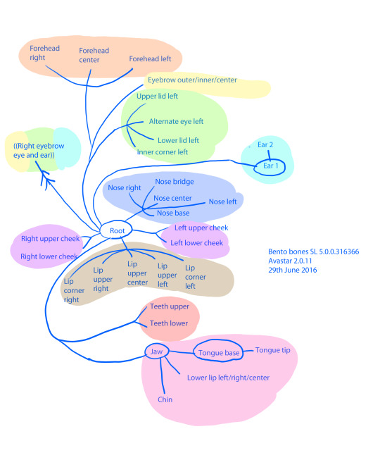
On the left, under Avastar tab -> Rig Display, Visibility, every bone has an "true" one thats used for rigging (Deform Bone Groups), and a 'display' bone (Control Bone Groups) usually laying over the exact same location for users to animate. This is to allow Avastar to set rotation limits on bones and use those circles to as 'handles'
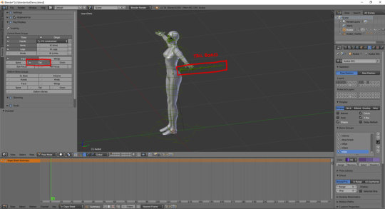
You should be in Pose Mode. While the armature is selected, use ctrl-tab to toggle between Pose mode and Object mode.
The deform bones are purple, control bones are green. You can toggle their visibility at Avastar tab -> Rig Display, Visibility.
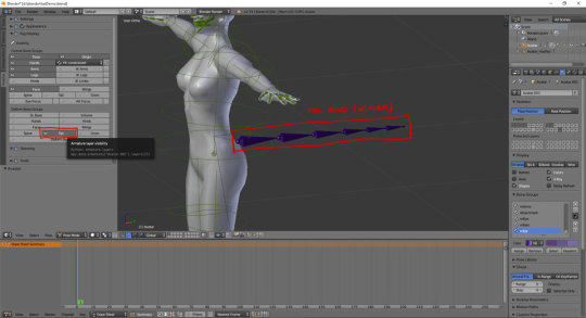
Select the base tail bone. Shift-S -> Cursor to Selected Shift-A -> Add Cylinder Give it 8 vertices to become an 8-sided cylinder then rotate and resize to fit over the tail.
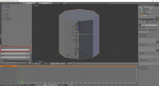
Select the cylinder, Edit mode, Ctrl-R, press '7' to give it 7 cuts.
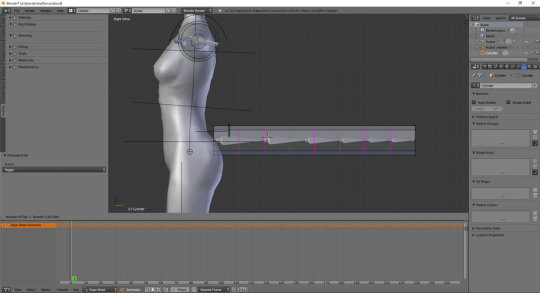
Press Tab for Object mode. Select Cylinder, hold-shift and select the Armature too.
At Avastar Tab, Skinning, Bind to Armature.
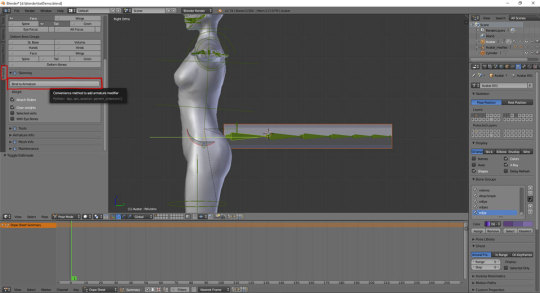
Now many things have happened. On the left, set turn off Control Bone Groups -> Tail (upper one) and turn on Deform Bone Groups -> Tail (lower one) Select Cylinder in Object mode, press ctrl-tab to enter Weight Paint mode. Now right click on each tail bone to see the weightings for them. On the far right, under Vertex Groups are the full list of bones influencing the object. This list can also be used instead of right-clicking on bones. Note that some undesired weights were acquired (i.e. mHindLimbsRoot)
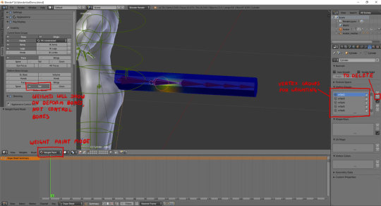
Avastar 2 Release Candidate 3 still has bugs needing to be ironed out. Errors might happen or all kinds of nearby bones might apply weights to the base of the tail, or the automatic weights just look off.
Select Vertex Groups -> mHindLimbsRoot and click on the - (minus) button.
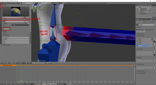
All the weights are off. Select mTail2, click on Tools. For Brush, set weight 1.0 , Multi-Paint on. For each bone, repaint the weights to be in bands. Use weight 0.0 to erase weights.
[ Refer to Addemdum Post 1 until I figure out how to embed videos :( ]
Avastar Deform Bone Groups visibility -> SL Base Select the mPelvis bone. Paint all the base vertices with 1.0 weight. This is to ensure the base of the tail stays stuck to the butt. This is also why mTail1 has 0.0 weight on those vertices as well.
Now test the tail. Turn off Deform Bone Groups -> Tail visibility, turn on Control Bone Groups -> Tail. Select and rotate each tail bone.
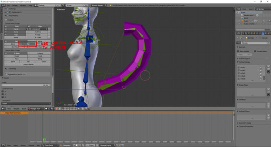
If nothing looks disastrously bad, select bones and press Alt-R to reset to Rest Pose.
Num Pad-7 for Top View. Change bottom pannel to Dope Sheet. Select Cylinder and Ctrl-Tab so it stops being pink, then select the first tail bone.
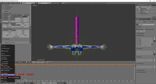
For each bone, rotate them 10 degrees on Z to curve the tail to the left. Select all tail bones, press I -> LocRot
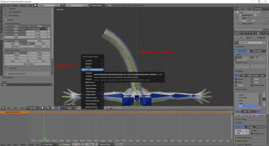
Keyframe created Selection tools are the same as 3dview. Press B and box-select the keyframe. Shift-D, type 30 (Creates a duplicate and places it 30 frames ahead) Repeat again to have another duplicate keyframe at frame 60
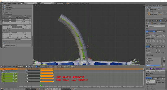
Select the keyframe at 30. Select all bones, Alt-R. Rotate each bone 10 degrees the other way to curve it to the right. Make sure all tail bones are selected, press I -> LocRot to save the keyframe.
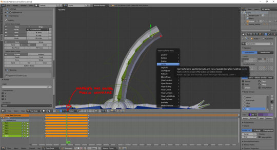
Slide the green line about to see how the animation goes
[ Addemdum post 2]
Select the Armature, then go to the Render -> Animation Export on the right. Loop animation -> on In: 1 Out: 60
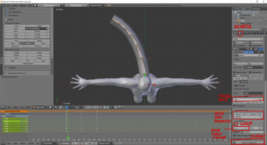
Export the animation. Select the tail mesh, Export -> Collada (Avastar) (.dae)
Upload the Animation. Upload the Mesh. Make sure Upload options -> 'Include skin weight' is turned on or it won't move.
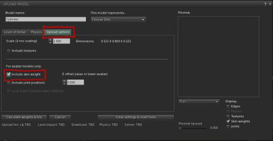
Wear the mesh. Play the animation.
9 notes
·
View notes
Text
Note to self
The ‘Bridge Edge Loops’ tool can be used to quickly connect 2 opposite edge loops with faces. Please remember this exists.
0 notes
Link
Note: He’s using ctrl+LMB to turn ‘Add’ sculpt brush into ‘Subtract’ on the fly. Also note several more shortcuts for brush size changing, etc.
Also: F for brush size change, and shift+F for strength change
0 notes
