#wingtips and landing gear
Explore tagged Tumblr posts
Visit Tumblr Blog
Explore Tumblr blogs with no restrictions, modern design and the best experience.
Last Seen Tumblr Blogs


Fun Fact
Tumblr has been providing a Korean-language service since 2013.
Text
Advancements and Innovations in Modern Passenger Aircraft: Safety, Efficiency, and Comfort
Passengers Aircraft: Evolution and Modern Innovations
Passenger aircraft have revolutionized global travel, connecting continents and cultures with unprecedented speed and efficiency. From the early days of aviation, when airplanes were small and rudimentary, to today's sophisticated jets capable of carrying hundreds of passengers, the evolution of passenger aircraft is a testament to human ingenuity and technological advancement.

The development of passenger aircraft began in earnest in the early 20th century. The introduction of the Boeing 707 in the late 1950s marked a significant milestone, bringing jet travel to the masses with its speed and comfort. This era of jet aviation was characterized by rapid advancements in aerodynamics, materials, and engine technology. The subsequent decades saw the introduction of wide-body aircraft, such as the Boeing 747, which became an icon of international travel with its distinctive hump and enormous capacity.
Modern passenger aircraft, like the Airbus A380 and the Boeing 787 Dreamliner, are marvels of engineering. These aircraft incorporate advanced materials, such as carbon-fiber composites, which reduce weight and improve fuel efficiency. Engine technology has also seen significant advancements, with newer engines providing more thrust while consuming less fuel and producing fewer emissions. Innovations in aerodynamics, such as winglets and raked wingtips, further enhance fuel efficiency by reducing drag.
International Civil Aviation Organization (ICAO): Ensuring Global Aviation Safety and Efficiency
The International Civil Aviation Organization (ICAO) plays a crucial role in the global aviation industry. Established in 1944 as a specialized agency of the United Nations, ICAO's primary objective is to ensure the safe and orderly development of international civil aviation. The organization sets international standards and regulations necessary for aviation safety, security, efficiency, and environmental protection.
ICAO's work is vital in creating a cohesive and standardized aviation industry. One of its key functions is the development and maintenance of the International Standards and Recommended Practices (SARPs). These SARPs cover all aspects of aviation, including aircraft operations, air traffic management, safety oversight, and environmental protection. By adhering to these standards, member states can ensure a high level of safety and efficiency in their aviation operations.
Moreover, ICAO facilitates international cooperation and dialogue among its 193 member states. Through various panels, committees, and working groups, ICAO addresses emerging challenges and technological advancements in aviation. This collaborative approach ensures that the global aviation industry can adapt to new developments and maintain a high standard of safety and efficiency.
Wingtips and Their Role in Aerodynamics
Wingtips and Their Role in Aerodynamics, the outermost parts of an aircraft's wings, play a significant role in improving aerodynamic efficiency and reducing fuel consumption. Traditional wingtips, which end abruptly, cause vortices to form at the wingtips, leading to increased drag and fuel consumption. To mitigate this, engineers have developed various wingtip designs aimed at reducing drag and improving overall performance.
One of the most common and effective wingtip designs is the winglet. Winglets are vertical or angled extensions at the wingtips that reduce the strength of the vortices, thereby decreasing drag. By improving the aerodynamics of the wing, winglets contribute to significant fuel savings and increased range. The use of winglets has become standard practice in modern aircraft design, with variations such as blended winglets, split-scimitar winglets, and raked wingtips being employed to optimize performance further.
Raked wingtips are another innovation aimed at enhancing aerodynamic efficiency. These wingtips are swept back and slightly upward, reducing drag and improving lift-to-drag ratio. Raked wingtips are commonly found on long-haul aircraft, such as the Boeing 787 Dreamliner, where fuel efficiency is paramount.
Landing Gear: Engineering for Safety and Performance
The landing gear is a critical component of an aircraft, responsible for supporting the aircraft during takeoff, landing, and taxiing. The design and engineering of landing gear systems are complex, requiring a balance between strength, weight, and reliability.
Landing gear systems can be broadly categorized into two types: fixed and retractable. Fixed landing gear is simpler and lighter, but it creates more drag, making it suitable primarily for smaller, slower aircraft. In contrast, retractable landing gear can be retracted into the aircraft during flight, reducing drag and improving aerodynamic efficiency. Retractable landing gear is standard on most commercial and military aircraft.
The landing gear comprises several key components, including the struts, wheels, brakes, and steering mechanisms. The struts absorb the impact forces during landing, ensuring a smooth touchdown. Modern landing gear systems often feature advanced materials, such as high-strength alloys and composites, to provide the necessary strength while minimizing weight.
Braking systems are crucial for safely stopping the aircraft after landing. Most commercial aircraft use multi-disc brakes, which provide the necessary stopping power. In addition, advanced braking technologies, such as carbon brakes and electrically actuated brakes, are increasingly being used to improve performance and reduce weight.
Aeroplane Lighting: Enhancing Safety and Visibility
Aeroplane lighting plays a vital role in ensuring safety and visibility during all phases of flight. Aircraft are equipped with various lighting systems, each serving a specific purpose and adhering to strict regulatory standards.
Navigation lights, also known as position lights, are used to indicate the aircraft's position and orientation to other pilots and air traffic controllers. These lights typically include red lights on the left wingtip, green lights on the right wingtip, and white lights on the tail. This standard configuration helps prevent collisions by allowing pilots to determine the relative direction and movement of other aircraft.
Landing lights are powerful lights mounted on the wings or fuselage, used to illuminate the runway during takeoff and landing. These lights enhance visibility for the pilots, ensuring a safe approach and touchdown. Taxi lights, on the other hand, are used to illuminate the taxiways and ramps, helping pilots navigate the airport environment during ground operations.
Strobe lights are high-intensity flashing lights located on the wingtips and tail. These lights improve the aircraft's visibility to other pilots, especially during takeoff, landing, and in-flight operations. Anti-collision lights, typically red beacons on the top and bottom of the fuselage, serve a similar purpose by making the aircraft more conspicuous.

Interior lighting is also critical for passenger comfort and safety. Modern aircraft feature advanced lighting systems that can adjust in color and intensity, creating a pleasant cabin environment. Emergency lighting systems, including exit signs and floor path lighting, are designed to guide passengers to safety in the event of an emergency.
In conclusion, the evolution of passenger aircraft, the regulatory framework established by ICAO, and innovations in wingtip design, landing gear, and aeroplane lighting have all contributed to making air travel safer, more efficient, and more comfortable. These advancements reflect the continuous efforts of engineers, regulators, and the aviation industry to meet the growing demands of global travel while prioritizing safety and sustainability.
#passengers aircraft#International Civil Aviation Organization#wingtips and landing gear#aeroplane lighting
0 notes
Text
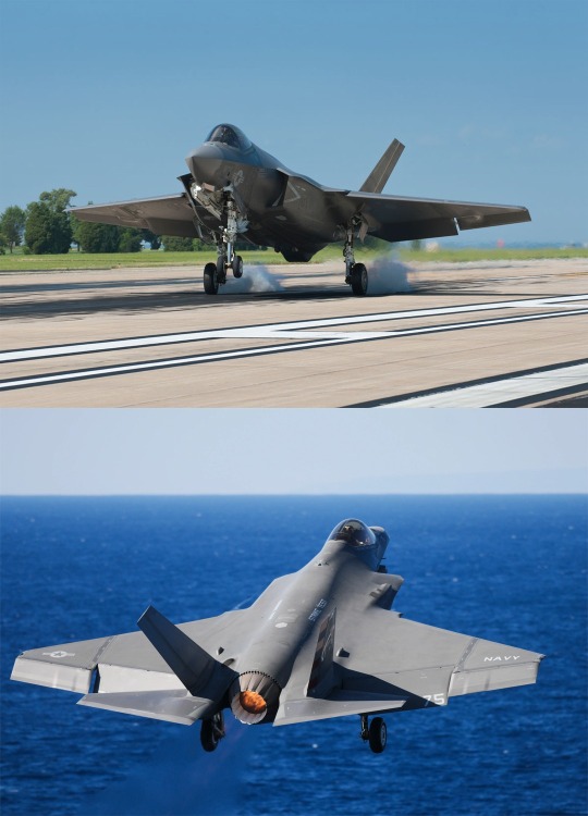
Why does the F-35C have larger wings?
The F-35C is the carrier variant of the F-35 Lightning II, a fifth-generation stealth fighter developed by Lockheed Martin for the U.S. Navy and the U.S. Marine Corps. The F-35C is designed to operate from aircraft carriers, which require special features and capabilities for launching and landing aircraft at sea. One of these features is the larger wings of the F-35C compared to the other variants, the F-35A (conventional takeoff and landing) and the F-35B (short takeoff and vertical landing).
The larger wings of the F-35C have several advantages for carrier operations. First, they provide more lift and control at low speeds, which are necessary for landing on a moving ship with a limited runway. The larger wings also allow the F-35C to carry more fuel and weapons internally, which increase its range and payload capacity. Also, the larger wings reduce the landing speed and ground roll of the F-35C, which improve its safety and efficiency on the carrier deck.
The F-35C has a wingspan of 13.1 meters (43 feet), which is 3.4 meters (11 feet) longer than the F-35A and 2.3 meters (7.5 feet) longer than the F-35B. The wing area of the F-35C is 62.1 square meters (668 square feet), which is 14.5 square meters (156 square feet) larger than the F-35A and 9.8 square meters (105 square feet) larger than the F-35B. The larger wings also have foldable wingtips, which reduce the width of the F-35C by 2.3 meters (7.5 feet) when folded, allowing for more space on the carrier deck.
The larger wings of the F-35C are not without drawbacks, however. They add weight and drag to the aircraft, which reduce its top speed and maneuverability compared to the other variants. The F-35C also has a lower thrust-to-weight ratio than the F-35A and F-35B, which means it has less power relative to its weight. Moreover, the larger wings require stronger and heavier landing gear to withstand the stresses of carrier landings, which further increase the weight and complexity of the aircraft.
79 notes
·
View notes
Text
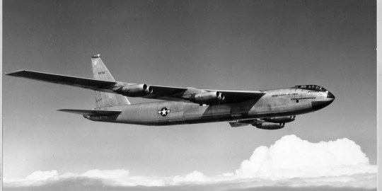
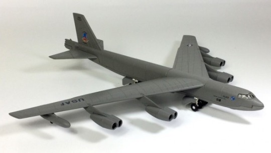
The prototype B-52s scrapped after First Lady Lady Bird Johnson’s ‘beautification’ of the US Air Force Museum
The B-52 Stratofortress
For more than 60 years, B-52 Stratofortress bombers have been the backbone of the strategic bomber force for the United States. The B-52 is capable of dropping or launching the widest array of weapons in the US inventory. This includes gravity bombs, cluster bombs, precision guided missiles and joint direct attack munitions. Updated with modern technology, the B-52 is capable of delivering the full complement of joint developed weapons and will continue into the 21st century as an important element of our nation’s defenses. The Air Force currently expects to operate B-52s through 2050.
The B-52A first flew in 1954, and the B model entered service in 1955. A total of 744 B-52s were built, with the last, a B-52H, delivered in October 1962. The first of 102 B-52H’s was delivered to Strategic Air Command in May 1961.
The prototype B-52s scrapped after First Lady Lady Bird Johnson’s ‘beautification’ of the US Air Force Museum: The story of the XB-52 and YB-52
The winning design
As explained by Scott Lowther in his book Boeing B-47 Stratojet & B-52 Stratofortress Origins and Evolution, the winning design for the XB-52, Model 464-49, transitioned to Model 464-67. While largely the same, there were some notable differences, most obviously the extension of the forward fuselage. Where 464-49 had the rear of the cockpit canopy behind the leading edge of the wing roots, 464-67 put the cockpit well ahead of the wing. The relatively vast expanse of spoilers on the wings were scaled down and the engine nacelles were reshaped. With those changes and an Air Force ‘letter of intent’ for B-52 tooling in March 1951, Boeing was ready to begin constructing two Model 464-67s.
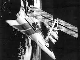
The prototype B-52s

These prototype B-52s were given the designations XB-52 and YB-52… X for ‘experimental’ and Y being the designation for ‘prototype.’ Typically an `experimental’ aircraft is built before a ‘prototype’, but in this case while the XB-52 (serial number 49- 230) rolled out on Nov. 29, 1951, and the YB-52 (serial number 49-231) followed on Mar. 15, 1952, the YB-52 flew first on Apr. 15, 1952. This was due to the XB-52 suffering damage during pneumatic system pressurization testing which required extensive repairs.
The prototype B-52s scrapped after First Lady Lady Bird Johnson’s ‘beautification’ of the US Air Force Museum: The story of the XB-52 and YB-52
The XB-52 followed the prototype into the air on Oct. 2, 1952. The first flight of the YB-52 lasted two hours and was powered by prototype YJ57-P-3 engines. Despite the difference in designations, the XB-52 and the YB-52 were essentially identical.
The prototype B-52s were largely similar to the production aircraft in appearance. An immediately distinguishing feature of both aircraft, though, was the cockpit. A tandem fighter-style canopy somewhat similar to that used on the B-47 was employed; it was low-drag and gave the pilot excellent visibility.
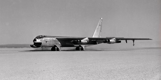
Pioneering the landing gear layout
The prototypes pioneered the landing gear layout that the rest of the B-52 fleet would employ. Somewhat similar at first glance to the bicycle arrangement used by the B-47, the gear used by the B-52 was quite different. Four separate dual-wheel bogies were stored within the B-52 fuselage, but instead of deploying straight down they deployed out to the sides, twisting around so that the bogies stored fore-and-aft ended up side-by-side. This gave the B-52 not a bicycle arrangement, but a quadricycle. The B-52 would comfortably sit level on its main landing gear and not tip to one side or the other. It still employed smaller outrigger gear near the wingtips, but this was to keep the wingtips from striking the ground during heavily laden takeoffs or bumpy landings.
‘Crabbing’ into the wind
Additionally, the forward bogies could rotate up to 20° side to side, allowing the B-52 to do something unique: land while ‘crabbing’ into the wind, the fuselage of the aircraft pointed well off the axis of the groundpath of the flight. This would permit safe landings in high winds.
The prototype B-52s scrapped after First Lady Lady Bird Johnson’s ‘beautification’ of the US Air Force Museum: The story of the XB-52 and YB-52
The prototypes had flapperons, ailerons and spoilers on the main wings. The ailerons were relatively small and located far from the wingtip; in fact, just outboard of the inboard engine pylon. A wingtip location for the ailerons would have given them more authority, but that would have put them in a much thinner section of the wing, a section much given to flexing. The inboard location was sufficient for the manoeuvring that the bomber was expected to perform.
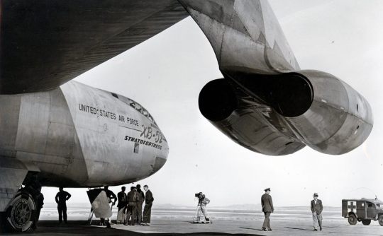
Folding vertical fin
In any event, the spoilers were to take care of the bulk of the control needs of the aircraft, and the ailerons would eventually find themselves redundant. Unlike the production aircraft that followed, the prototypes did not have the capability for inflight refuelling. Neither did they, initially, have the external fuel tanks that generally graced the outer wings of production model B-52s, but such tanks were eventually added later in the testing phase.

B-52H print
This print is available in multiple sizes from AircraftProfilePrints.com – CLICK HERE TO GET YOURS. B-52H Stratofortress 2nd BW, 20th BS, LA/60-0008 “Lucky Lady IV”.
The horizontal stabilizers were all-moving, but this was meant for trim stabilization. Actual control was via slim elevators along the trailing edge. The elevators had, through the B-52F, trim tabs. An important but rarely noted feature not only of the prototype B-52s but of all B-52s that followed was the folding vertical fin. The fin was, at least until the G-model, a vast structure; too tall by far to allow the B-52 to fit within standard hangars. So it could fold over 90-degrees, greatly reducing the effective height of the aircraft. Unlike naval aircraft with wings that fold to fit in the limited space on board aircraft carriers, the fielding fin is not a self-contained system — an external crane is needed to lay it over and raise it back up again.
Prototype B-52s were hand-made
The prototypes were essentially hand-made at the Boeing Seattle factory. Production methods were not used as the jigs were not finalized; the equipment and instruments employed were also often not what would become standard. Neither prototype was fitted with defensive weapons; the tail turrets were represented by static fairings, with the painted-on lines.
The YB-52 was donated to the US Air Force Museum on Jan. 27, 1958, having flown for 783 hours. It was on display for a time but due to a ‘beautification’ scheme orchestrated by First Lady Lady Bird Johnson, both the XB-52 and YB-52 were scrapped sometime in the 1960s. Exactly how the official museum of the United States Air Force was ‘beautified’ by converting one of the most beautiful aircraft ever built into razor blades and soda cans is not adequately explained in the available literature.
Boeing B-47 Stratojet & B-52 Stratofortress Origins and Evolution is published by Mortons Books and is available to order here.
Photo credit: U.S. Air Force
B-52 Model
This model is available from AirModels – CLICK HERE TO GET YOURS.
Dario Leone
Dario Leone is an aviation, defense and military writer. He is the Founder and Editor of “The Aviation Geek Club” one of the world’s most read military aviation blogs. His writing has appeared in The National Interest and other news media. He has reported from Europe and flown Super Puma and Cougar helicopters with the Swiss Air Force.
@kadonkey via X
56 notes
·
View notes
Text
I often see Mi-24s posted and being misidentified by the variant. So I put together a Hind variant guide for telling apart the major production models.
The first and most obvious is the Mi-24A Hind A/B. These were the earliest variant and had only a short production run in the early 1970s. Its easily identified by the "greenhouse" canopy design that was soon redesigned into the version found on all other Hinds.

Next is the Mi-24D Hind D. This one featured the redesigned cockpit mentioned above but shared a lot of the same technology of the Mi-24A. It entered service a year later in 1973.

The Mi-24D is often the most confused variant with the similar looking but upgraded Mi-24V Hind E that would enter service in 1976.

These two variants can be distinguished by the radio transmitter located under the nose on the portside. The earlier Mi-24D has a smaller and oblong shaped transmitter that is able to rotate left and right. The Mi-24V has a larger and more rounded transmitter that is fixed in place.


The change in design between these two transmitters is due to the change in armament between the two variants, specifically the guided anti tank missiles. These are usually mounted on the wingtips and are another way to tell at a glance which variant it is. The Mi-24A/D was equipped with the older AT-2 Swatter missile which sits mounted atop a guide rail and has four large stabilizing fins.

Mi-24V's were equipped with newer AT-6 and later AT-9 Spiral missiles which required a new guidance system, hence the redesign. These missiles are much narrower and contained in a tube prior to launch.

The Mi-24P Hind F is essentially a Mi-24V with the 12.7mm gun replaced with a twin barrel 30mm cannon mounted on the starboard fuselage.

The lack of a chin turret is fairly obvious to spot when identifying the Mi-24P. It also saw a reorganized front cockpit but that cant be seen from the exterior.
The final and most modernized Mi-35M is quite different from the earlier variants. It has new avionics and optics, a new 'X' tail rotor, shortened wings with only two pylons instead of the usual three, a new cannon mounted in the nose, and non-retractable landing gear.

Its nearly a new helicopter compared to the older V and P variants.
I'd also like to point out that there are Mi-25 and Mi-35 (not to be confused with the Mi-35M) designations thrown around too. The Mi-25 was essentially a Mi-24D that was produced with slightly different avionics and intended for export to allied countries outside the USSR. The Mi-35 is a Mi-24V intended for the same.
So as a quick summary. The Mi-24A has a greenhouse canopy. The Mi-24D has an oblong transmitter and AT-2 missiles. The Mi-24V has a round transmitter and AT-6/9 missiles. The Mi-24P has a 30mm side mounted cannon. And the Mi-35M has new sensors, short wings, X tail rotor, and fixed landing gear.
9 notes
·
View notes
Text
Space Shuttle Development, Phase B: North American Rockwell and General Dynamics B9U/NAR-161-B


North American and General Dynamics B9U / NAR-161-B proposed their final Phase B shuttle proposal on June 25, 1971.


"The fully reusable 'B9U / NAR-161-B' configuration would now weigh 2,290t at liftoff vs. the Phase-A limit of 1,587t and the total estimated cost of the development project had doubled, to almost $10 billion. The thrust of the space shuttle main engines had to be increased from 1,850KN to 2,450KN. Part of the problem was the shuttle now would have to be a much more versatile and capable vehicle than originally anticipated, since the space station and the manned lunar/planetary program evaporated in 1970. Critics in Congress contended that it was 'a project searching for a mission.' As a result, the new space transportation system was instead increasingly being promoted as a low-cost 'space truck' for unmanned NASA & USAF satellites."


"The North American Rockwell 'NAR-161-B' orbiter was designed for carrying a crew of two plus up to ten passengers in the forward crew module. Note the four deployable landing jet engines on top of the vehicle; NASA was planning to use modified F-15 or B-1B aircraft jet engines on some missions and for ferry flights from test sites or alternative landing fields. But the jets would be omitted for heavy-lift missions since the additional weight greatly reduced the shuttle's payload capability. The thermal protection system was based on silica tiles. The blended wing/body design was chosen for uniform load distribution. It would have produced a 2300-kilometer crossrange capability to satisfy USAF reentry requirements; North American also decided to replace the wingtip fins with a single vertical tail. The 2,450KN main engine thrust upgrade was motivated in part by the need to have a single engine-out abort capability. Analysis showed that the orbiter still would be able to return to the launch site after a single orbit in case one of its two main engines failed during ascent, but only if the engines were powerful enough. Unlike McDonnell-Douglas (who proposed to use RL-10s), North American favored a brand new oxygen/hydrogen 45KN-thrust orbital maneuvering system (OMS) engines. Three OMS engines would have been carried for orbit insertion, orbital changes and the de-orbit burn."

"General Dynamics' final 'B9U' booster design differed considerably from the earlier straight-wing 'B8D' concept. The landing jets were moved from the nose back to the delta wing in order to reduce the launch drag & heating effects and to minimize the jet engine exhaust effects on stability, control and drag. General Dynamics felt the delta wing would provide better stability & control over the entire flight regime than the B8's straight wing. It would also create more room for the main landing gear and jet engine installation. The gross liftoff mass was 1,886.2t including a jet fuel load of 62.2t for the 850km flight back to the launch site. The high staging velocity (3300m/s) and altitude (73.8km) created some problems since the booster would have to be very large, require a relatively advanced thermal protection system and carry lots of jet fuel for the return flight. The contractors also examined downrange landing sites or in-flight propellant transfer in order to reduce the amount of booster jet fuel. NASA also seriously considered a proposal to use gaseous hydrogen rather than jet fuel since it would have saved thousands of kilograms, but decided against the idea in the end since it would have increased the technical risk."
North American Rockwell Phase-B shuttle orbiter docks with modular space station.
"Payload capability (without landing jets): 29,484kg into a 185km 28.5 deg. Orbit; 18,144kg into a 185km 90 deg. polar orbit; 11,340kg into a 500km 55 deg. orbit with landing jets installed on orbiter and 20,411kg without landing engines.
Cost per mission: $100-200/lb. [1970 rates] or $950-$1900/kg in 1999. 75 missions/year max. Space station rescue mission capability within 48 hours of emergency call.
Liftoff Thrust: 2,606,810 kgf. Total Mass: 2,188,488 kg. Core Diameter: 10.4 m. Total Length: 98.0 m.
Stage Number: 1. 1 x Shuttle R134C-1 Gross Mass: 1,886,200 kg. Empty Mass: 290,000 kg. Thrust: 29,370-32,233.575 KN. Isp: 442 sec. Burn time: 209 sec. Isp(sl): 392 sec. Diameter: 10.4 m. Span: 43.9 m. Length: 82 m. Propellants: Lox/LH2 No Engines: 12. SSME Study
Stage Number: 2. 1 x Shuttle R134C-2 Gross Mass: 383,260 kg. Empty Mass: 121,560 kg. Thrust (vac): 5,624.8 KN. Isp: 459 sec. Burn time: 264 sec. Isp(sl): 359 sec. Diameter: 4.6 m. Span: 32.6 m. Length: 62.8 m. Propellants: Lox/LH2 No Engines: 2. SSME Study

- information from "INTRODUCTION TO FUTURE LAUNCH VEHICLE PLANS [1963-2001]" by Marcus Lindroos: link
SDASM Archives: 08_00941, 08_00943, 08_00944
Mike Acs's Collection: link, link
Numbers Station: link, link, link, link, link
source
Boeing image: 71SV13043
#Space Shuttle Development#Phase B#North American Rockwell General Dynamics B9U/NAR-161-B#North American RockwellNAR-161-B#NAR-160-B#General Dynamics B9U#concept art#Space Shuttle Phase B#Space Shuttle#Orbiter#NASA#Space Shuttle Program#June#1971#B9U#my post
59 notes
·
View notes
Text

Jay Sherlock has produced a companion volume to his AD Skyraider book published by Aero Research. See http://www.aeroresearchcds.com/book_shelf.htm for price and ordering information. As you might expect, the bulk of the monograph is devoted to the various versions of the Sabre, including the Canadian and Australian-built ones. Reviews of many of the F-86 kits are provided along with a listing of decals and aftermarket parts. One very useful section is devoted to a primer on Sabre/Fury wings. At least a couple of pages are devoted to each of the Fury types, listing both the recommended kit in each scale and the numerous changes required to create one from an F-86 kit. There are few illustrations, however, and an occasional error or omission. For example, the XFJ-2 windscreen was not the same as the F-86's. (I also think that the bulges under the wingtips of the XFJ-2 contained cameras to photograph the landing gear and tailhook, not flotation bags.) The FJ-2 inlet was slightly but notably different from the F-86's and the increase in depth of the FJ-3's inlet was in addition to the FJ-2 change. The FJ-3 was originally equipped with the barrier guard on the belly but it was subsequently deleted. The change to add external stiffening to the elevators isn't mentioned. The FJ-4 options list states that the vertical fin of the prototypes was 11 inches shorter than the prototypes (which I wasn't aware of) but not that 18 inches was clipped from each side of horizontal tail. As a result, the information and drawings provided here: http://tailspintopics.blogspot.com/2009/10/fj-fury.html and here: http://tailspintopics.blogspot.com/2011/04/fj23-fury-redux.html will still be of use to the modeler, as will the Ginter Naval Fighters monograph for the type being modeled. I am pleased to report that were a few revelations. For example, I had noted that the guns were removed from some FJ-4Bs and vents added to the aft end of the panel covering the gun bay but didn't know why. Jay states that the cannons on the left side were removed on some aircraft to allow installation of a back-up electrical generator. Joe Baugher provided details in his excellent series of posts on U.S. Navy airplanes: "During service, some FJ-4Bs had the port pair of 20-mm cannon removed so that a standby generator system could be installed. This standby generator provided power backup in case the main generator failed--without the backup it was nearly impossible to fly at night or under instrument conditions for more than a few minutes with only battery power. At the same time, the standard ejection seat was replaced by a Martin-Baker seat that provided the ability to eject safely at much lower altitudes" With respect to the cannon deletion, Dave Collier noted in an email: "In the period that I worked on FJ-4Bs (1962-64) our squadron had several aircraft with only two cannon. We were told the mod was part of the Bullpup installation but the backup generator installation seems to make more sense since you see lots of photos of A/C carrying Bullpups with the port guns installed." Dave also provided the following observation: "In photos of FJ-4Bs late in their service life you will find aircraft with bare metal in the area of the cannon blast tube panel. Paint was removed from this area after panels came apart during firing runs. The bare metal was consider necessary to help detect small panel cracks before severe damage was done. While stripping the panels I found that most had at least five coats of paint."
5 notes
·
View notes
Note
if you're doin em for drabbles - ❓ - "is this what you want?" with BlurrLine? 👀
On my hands and knees. I truly don't know what happened here, I think I got possessed.
❓ - "Is this what you want?"
This was a terrible idea.
Blurr’s been pacing this rooftop for hours, enough to practically leave his tire treads in his wake. He’d sent the invitation before midday, in what he’s now decided with increasing insistence was a state of delirium. And/or his central processor blowing a fuse. Or maybe some warped sense of survivor’s guilt. The point is that it’s now well past evening, well past the time he had listed on the invitation for them to meet. If anyone is going to show up, Blurr thinks as he stops to vigorously tap his pede.
Maybe he should give up and go inside, maybe it’s best that he take this as a sign to forget about this stupid idea, to forget about him. Maybe the invitation hadn’t gone through at all - Blurr had put it through half a dozen layers of encryption to ensure no-one else could possibly get their servos on it. Maybe he’s not coming and Blurr’s standing around on this roof for nothing. Maybe, maybe, maybe.
Blurr’s audio receptors catch on the rumble of a jet engine, quiet but getting closer. His helm snaps up to the dark sky; his body’s first instinct is to seize up for action, but then a rush of relief, joy and apprehension flood over his spark. The jet’s shape is less sharp than a usual Decepticon’s, he recognises the wingtips. The most telling clue of all is when the jet banks and gently curves down towards the rooftop, and the soft light fixtures illuminate a pink and blue paint job.
Blurr steps back, feeling like his fuel pump is in his throat as the jet transforms, plating shifting in a fluid turn of gears and actuators. Turbines whip up a small whirlwind which disturbs the scenery, and Blurr raises an arm, protecting his faceplate. The pink Decepticon lands a few feet before Blurr, wings clicking into place on his back.
They stare at each other for a long moment, two sets of blue optics that don’t dare look away. The Decepticon - Flatline, who really came and accepted the invitation and is here - tilts his helm lower, a breathing mask retracting from his faceplate to reveal a set and sceptical frown.
“You came, I almost can’t believe it I mean it wasn’t the safest course of action and in fact there was a noticeable element of danger to coming but you did and I was beginning to think you wouldn’t.” There’s a smile on the corners of Blurr’s lips even though his servos are shaking. Flatline glances over his shoulder pauldron and ducks further into the rooftop seating area, hoping no-one managed to see him arrive.
“I didn’t expect to see you again.” Flatline’s voice is more controlled than usual. Away from any prying Autobot optics, Flatline circles Blurr; Blurr doesn’t miss how he’s keeping a distance, taking an assessment, gauging the situation. He must be expecting a trap. It’s a clever deduction, and Blurr expected the same. Blurr shifts, doing a slow spin so he can keep Flatline in view. That lilting voice is still hanging in his processor, but Flatline is still a Decepticon, and Blurr is a well-trained intelligence agent.
“I didn’t expect to see you either after the ship and what you did both to me and for me the former of which I’m still sore about by the way, you’re lucky that I was given a healthy diagnostic once the medibots gave me the once-over.” Blurr places a servo on his hip, giving a firm glare to make a point. Flatline slows to a stop, and a chuckle escapes his lips. Blurr straightens, his spark flip-flopping in its chamber at the sound.
“There shouldn’t be any long-lasting damage from anything I gave you.” Another helm tilt, to the side this time, and amusement plays on the guarded look in his optics. Lovely, shining blue optics- “Is that all you called me here for? Verification on your check-up?”
“No no no of course not.” Blurr shakes his helm quickly. He glances across their surroundings; a comfortable seating area for the tenants of the building’s habitation suites, lit with soft lamps dotted above the different benches and chairs. The current time of night gives everything a cosy and secluded atmosphere, one that might be more perfect than his original plan. Flatline’s question hangs unanswered, and Blurr chews on it for a second longer, averting his optics. The Decepticon’s wings twitch higher, slightly more flared. “I just wanted to talk to you again I suppose, I have questions and I didn’t trust trying to relay them to you over encrypted messages that might be found by someone else. I couldn’t get you out of my helm and trust me I tried and tried and tried but I couldn’t take it anymore I had to see you again.”
Flatline brightens, although it seems like he tries not to.
“You…missed me?” It’s barely even a question. Blurr crosses his arms, which causes Flatline to hazard a single step closer towards him. Ah, Blurr had almost forgotten about that; how Flatline always found it amusing and ‘cute’ when he gets fluster- defensive. He doesn’t reiterate how true it is that he could hardly think about anything else except this moment for the whole cycle. Instead, he uncrosses his arms to gesture in invitation to the bench closest to the two of them. Flatline’s optics flick between the bench and to Blurr, but he stalks over and takes a seat, folding one leg over the other. Blurr is quick to join him.
Blurr sets his servos on his knees, a digit tapping rapidly against the blue metal. He can feel Flatline’s attention closely on him, roaming up and down over his form, and he resists the urge to squirm. Instead, he goes for the spark of the matter; the burning question that’s been bothering him for weeks.
“Why did you help me escape? You never explained why and it doesn’t make any sense to me why you would stick out your neck cabling to release a prisoner, especially not when I’m an Autobot and you’re a De-”
“The same reason I kissed you.” Flatline cuts him off, talking over the word Blurr was about to say next. His pauldrons relax, and his voice calms from the bite it temporarily had, “....Twice.”
“Three times.” Blurr corrects, holding up the same number of digits.
“At least one of those times was initiated by you.” Flatline insists with raised brows. Blurr sits straighter, puffing out his chestplate with a huff. The corners of Flatline’s lips start to curl, primed and ready to retort to whatever Blurr says next in defence. He’s arrogant, too clever for his own good, cocky, and it gives Blurr a rush of warmth that could be either anger or affection. As a result, all he does is deflate, and stare at Flatline as he grumbles under his breath. Flatline cracks a full smile, and pats the servo Blurr has tapping his knee. It’s hardly a consolation, but at least the pink medibot’s attention drifts away - he sits back, helm tilting up to look at the night sky. That’s right, Blurr remembers, optics widening slightly, The first Cybertronian sky Flatline’s seen in eons. He’s been cooped up in ‘Con laboratories all this time, and from the soft sigh that leaves his lips, you’d think he’d been left starving without the pinpricks of light dotting the dark backdrop. Blurr doesn’t dare move to disturb the vision sitting next to him. Flatline looks pretty like this, with the lamplight shining on the curves of his pink frame, and oh so tempting…especially when Blurr isn’t being held captive. His gaze follows over Flatline’s form, but it lingers on the syringe built into his arm, and Blurr is hit with a cold reminder of the danger to this reckless idea.
A frown sours Blurr’s features, and he clears his throat. Flatline’s helm snaps back down to look at him, just fast enough to make Blurr tense. His vocaliser seizes, but he forces it to reset.
“See the fact of the matter is you and I clearly have some affection for each other based on our prior poor calls in judgement and I thought that might have gone away on its own but it hasn’t. I really really really must have caught some form of malware because all day every day for the last few weeks I haven’t been able to stop thinking about you.” His expression softens into something close to anguish, shaking his helm as he blurts out a confession he wishes he had practised more. The ground unfortunately doesn’t seem like it’s going to do him a favour and swallow him anytime soon. “The reason I sent you an invitation and found the most private location to meet is because despite knowing this is dangerous beyond measure and will likely end in one or both of us being killed, I couldn’t bear not being able to see you again in person.”
He points his optics at the floor and keeps them there, refusing to look at Flatline. A unbearably long moment of silence passes, and Blurr’s servos fidget in his lap. He’s tempted immediately to start denying everything, say it was a joke or a deception and run as fast as he can out of the building. Surely, this is where Flatline laughs at him, and then impales him clean through and disposes of a loose end.
Flatline shifts. Blurr braces himself. Flatline scoots closer towards him on the bench, and slowly, ventures taking one of Blurr’s servos in his own. Blurr’s helm shoots up to look at him, watching as Flatline raises their interwoven digits. The look on his faceplace isn’t mocking, he looks flattered, and a little smug.
“Freedom looks good on you.” He presses a kiss to Blurr’s knuckle-joints, optics half-lidded and fixed on Blurr as he does so. Blurr’s cooling fans click on, sounding louder in the otherwise peaceful space, and he quickly straightens and paws at his own plating, trying to shut them off. Flatline chuckles, and releases the servo he’s holding. He shifts closer again, and starts to lean in. Blurr stops trying to manually disable his own internal systems and freezes entirely, although his processor is running faster than he ever could with a million whirring thoughts and hesitations. His servos hang in the air, unsure where to put themselves as Flatline cups his cheek. His helm tugs away slightly in the soft touch on impulse, and Flatline pauses. Blue optics watch Blurr intently.
“Is this what you want? Really?” Flatline’s thumb-digit brushes over his cheek. Blurr searches his faceplate. It’s so close, so close Blurr could move just a little bit forward and break the remaining distance so easily. His engine revs, and rumbles steadily to match the high-pitched noise he makes while his focus grapples with having Flatline’s lips so close to his own.
“Yes, yes yes please.” Blurr breathes. Flatline surges forward and kisses him. All at once Blurr is swept away by a tidal wave, washed over by delight and terror in equal measure and sparks are sent shooting through his entire circuitry. This is an awful idea and he knows that but his servos clutch onto Flatline as if his life depends on it. Flatline moves again until they’re flush against each other, kissing underneath the stars and soft lamplight above.
Blurr can kick himself for this decision later. Right now, his spark feels so full it might burst, and he’s too enraptured by Flatline’s intoxicating presence to think about ‘later’.
#thank you for asking!#BlurrLine#my writing#i PROMISE if I'm sent any more of these prompts I'll keep them short#Flatline (OC)
5 notes
·
View notes
Text
Aircraft Design and Engineering Market: Projected Growth of 4.70% CAGR by 2032

Aircraft Design and Engineering Market: A Comprehensive Analysis of Growth Trends and Opportunities
The Aircraft Design and Engineering Market has witnessed significant growth over recent years, driven by advancements in aerospace technologies, the rising demand for commercial aviation, and the increasing emphasis on military aviation capabilities. In 2022, the market size was valued at USD 34.2 billion and is projected to grow to USD 54.6 billion by 2032, representing a compound annual growth rate (CAGR) of 4.70% during the forecast period (2022–2032). This robust growth reflects the surging investments in aircraft development, modernization, and innovations that aim to improve efficiency, safety, and sustainability.
Browse Report – Explore the report’s contents, sections, and key insights by browsing through its detailed information.
Market Drivers: Key Factors Fueling Growth
Rising Demand for Fuel-Efficient Aircraft The aviation industry's ongoing pursuit of reducing carbon emissions and operating costs has driven the development of fuel-efficient aircraft. Advanced design and engineering innovations, such as lightweight materials and aerodynamic enhancements, are essential for meeting environmental regulations and consumer demand for sustainable travel.
Growth in Commercial Aviation The growing global middle class and the expansion of low-cost carriers (LCCs) have contributed to increased passenger air travel. As airlines seek to expand their fleets and replace aging aircraft, the demand for advanced aircraft design and engineering services continues to rise.
Military Modernization Programs Governments worldwide are heavily investing in upgrading their defense capabilities, with a strong focus on next-generation military aircraft. Fighter jets, unmanned aerial vehicles (UAVs), and transport aircraft are driving growth in the military aviation segment, bolstering the demand for cutting-edge engineering and design services.
Technological Advancements Innovations such as additive manufacturing (3D printing), digital twins, and artificial intelligence (AI) are transforming the aircraft design and engineering process. These technologies enhance precision, reduce production costs, and shorten development cycles, providing a competitive edge to industry players.
Market Segmentation
The Aircraft Design and Engineering Market is segmented based on aircraft components, operations, end-use, and regions.
1. Aircraft Components
Engine: Aircraft engines remain a critical focus for innovation, emphasizing fuel efficiency and reduced emissions.
Wings: Advanced wing designs, such as blended wing bodies and folding wingtips, are gaining prominence.
Fuselage: Lightweight composite materials like carbon fiber are being increasingly adopted to enhance structural integrity while reducing weight.
Landing Gear, Tail, Nose, and Pylon: These components are also undergoing redesigns to improve aerodynamics and durability.
2. Operations
Design: The use of CAD (Computer-Aided Design) and AI-driven modeling tools is revolutionizing aircraft design processes.
Manufacturing: Advanced manufacturing techniques, including robotic assembly and additive manufacturing, are reducing production timelines.
Analysis and Testing: Virtual testing and simulations are replacing traditional methods, ensuring safety and performance efficiency.
Maintenance, Repair, and Operations (MRO): With the increasing size of global aircraft fleets, MRO services play a crucial role in sustaining operational efficiency.
3. End-Use
Commercial Aviation: Dominates the market, fueled by rising passenger demand and fleet expansion initiatives.
Military Aviation: Gaining traction due to defense modernization programs and the rising demand for UAVs.
4. Regional Analysis
The market exhibits strong regional variations in growth, driven by differing economic conditions, technological advancements, and government initiatives:
North America: Leading the market due to robust investments in both commercial and military aviation. The presence of major players like Boeing and Lockheed Martin contributes significantly to the region's dominance.
Europe: Home to major aircraft manufacturers such as Airbus, Europe focuses heavily on sustainable aviation technologies and R&D initiatives.
Asia-Pacific: The fastest-growing region, driven by increasing air travel demand in countries like China and India, as well as growing investments in indigenous aircraft programs.
Middle East & Africa: Gaining prominence as a hub for MRO services, with rising investments in aviation infrastructure.
Latin America: Witnessing gradual growth, primarily led by rising tourism and commercial aviation expansion.
Competitive Landscape
The Aircraft Design and Engineering Market is highly competitive, with several key players vying for market share through innovation and strategic collaborations. Prominent companies in the industry include:
The Boeing Company
Airbus SE
Lockheed Martin Corporation
Raytheon Technologies Corporation
General Electric (GE) Aviation
Rolls-Royce Holdings PLC
Safran SA
These companies are leveraging advancements in digital technologies and sustainability solutions to strengthen their market position. Strategic alliances, mergers, and acquisitions are common tactics to expand their capabilities and global reach.
Future Outlook and Opportunities
The Aircraft Design and Engineering Market is poised for continued growth, driven by emerging opportunities such as:
Urban Air Mobility (UAM): The rise of electric vertical takeoff and landing (eVTOL) aircraft is creating a new avenue for design and engineering innovation.
Green Aviation: Sustainable aviation fuel (SAF), hydrogen-powered aircraft, and electric propulsion systems are reshaping the industry landscape.
Digital Transformation: The adoption of digital twins, predictive analytics, and cloud-based platforms will continue to enhance efficiency and cost-effectiveness in aircraft development.
Autonomous Aircraft: Advancements in artificial intelligence and autonomous systems present significant opportunities for military and commercial applications.
Conclusion
The Aircraft Design and Engineering Market is entering an exciting phase of transformation, driven by technological advancements, evolving consumer demands, and environmental considerations. As the industry moves toward more sustainable and efficient aviation solutions, the role of innovative design and engineering processes will become even more critical. With a projected market size of USD 54.6 billion by 2032, stakeholders across the value chain are poised to benefit from the growth opportunities presented by this dynamic market.
Request Free Sample Report - Receive a free sample report to preview the valuable insights and data we offer.
By leveraging cutting-edge technologies and adapting to emerging trends, industry players can stay ahead of the curve, ensuring a future-ready aviation ecosystem that meets the needs of both commercial and military sectors.
About US
Market Research Future (MRFR) is a global market research company that takes pride in its services, offering a complete and accurate analysis about diverse markets and consumers worldwide. Market Research Future has the distinguished objective of providing the optimal quality research and granular research to clients. Our market research studies by products, services, technologies, applications, end users, and market players for global, regional, and country level market segments, enable our clients to see more, know more, and do more, which help answer your most important questions.
Contact US
Market Research Future (part of Wants tats Research and Media Private Limited),
99 Hudson Street,5Th Floor New York 10013, United States of America
Sales: +1 628 258 0071 (US) +44 2035 002 764 (UK)
Email: [email protected]
0 notes
Text
Aircraft General Supply: Top Components of an Aircraft
The world of aircraft is fascinating, full of complex components and systems that work together to keep passengers secure and comfortable. Whether you're a seasoned traveler or a curious aviation enthusiast, learning about the different parts of an airplane is fundamental to appreciating the incredible feat of human engineering, which is flight. Many aircraft parts work together, from the wings and engines to the cockpit and cabin, to provide a smooth and efficient flight. Understanding the general supply of aircraft can help a lot.

The Anatomy of an Airplane
An airplane comprises many distinctive parts, each crucial to ensuring a safe and successful flight. The main components of an aircraft include the wings, engines, cockpit, fuselage, avionics, landing gear, and brakes.
Wings and Their Components
The airplane's wings generate lift, a fundamental element of flight. The shape and size of the aircraft wings can vary based on the variety of aircraft, but they all work on the same principle of creating a difference in air pressure. The wings have several components, including wingtips, flaps, ailerons, and spoilers.
Engines and Propulsion Systems
Engines provide the forward thrust needed to move a plane through the air. Aircraft utilize a variety of types of engines, including turbojet, turboprop, and turbofan engines. While each engine type works differently, they all use the same basic principle of taking in air and burning fuel to create thrust.
Cockpit and Flight Controls
The cockpit is where the pilots sit and control the airplane. This elaborate network of instruments and controls enables pilots to navigate, communicate, and monitor the aircraft's performance. The flight controls are also located in the cockpit, which controls the airplane's movements. These controls include the yoke, rudder pedals, and throttle.
Landing Gear and Brakes
An airplane's landing gear supports the aircraft's weight during takeoff and landing. It's a multifaceted system of struts, wheels, and brakes that allows the plane to land and take off smoothly. The brakes are also an integral part of the landing gear, slowing the aircraft during landing and taxiing.
Fuselage and Cabin
The fuselage is the main body of the airplane. It houses the passengers, cargo, and other critical aircraft components. Located inside the fuselage, the cabin is where the passengers sit during flight. The cabin is designed for comfort and safety, with features such as oxygen masks, overhead storage compartments, and emergency exits.
Avionics and Navigation Systems
Avionics are the electronic systems used to control and monitor an airplane. These systems include the communications, navigation, and flight management systems. The communications system transmits information to air traffic control and other planes. In contrast, the navigation system determines the aircraft's position and route. The flight management system is a sophisticated computer system that enables pilots to plan and execute flights, factoring in weather conditions, air traffic, and fuel consumption.
In conclusion
Modern air travel is a testament to human ingenuity. Beneath an airplane's sleek exterior lies a breathtaking network of interconnected systems. Each component, from the aerodynamically designed wings to the state-of-the-art navigation equipment, plays a vital role in the seamless operation of the aircraft. By delving deeper into the workings of these individual parts, we gain a newfound respect for the technical marvel that empowers us to soar through the skies.
#aircraft general supply#aircraft parts distributors#aircraft parts suppliers#aircraft maintenance engineering#aircraft parts#single engine aircraft
0 notes
Text

THE JOY OF GERIATRIC PHOTOGRAPHY :
I have found the ultimate *"Crip Camera"- a Nikon P1000. It is the World's largest 'point & shoot' camera with the size and weight of a D850 with a Sigma Art lens.
I no longer possess the slender, easy-moving, contortion-abled body of my youth. My lungs are shot from 40 years of smoking to the point I run out of breath when doing hard-core critical thinking. I'm a rolly-polly fat fuck in a borderline diabetic, bursitis, and gout-infused physique. I walk like a cripple for maybe a hundred feet before I have to either sit down or fall down.
"Falling down" is NOT an option!
With the "Crip Camera", I have versatility in a small package :
- one camera instead of two.
- one non-interchangeable lens, vice four interchangeable lenses.
- a seven by twelve over-the-shoulder pouch, vice an eighteen by thirty backpack that opens on the 'wrong end' to protect all that heavy gear from being ripped off while you're walking with it.
This picture (of either a 172 or a 182) at the south end of the ramp was taken from the north end of the ramp at the "T" line by the restaurant.The lens was zoomed to a focal length of 180mm - the 35mm camera equivalent of 990mm. It is also the same spot where I took a picture of a father and daughter by the wingtip of an orange SGS 2-33 glider (hereto forever known as the "Great Pumpkin"). It will be uploaded after processing (editing).
The next project will be how well the "Gimp" photographs airplanes that are taking off and landing - showing the propellers as actually turning, rather than every airplane doing a "dead stick" landing.
Apparent sharpness will be critical as well (sounds like something Yogi Berra would have said).
FLY NAVY !
0 notes
Text
Dragon Lady comes home...

The U-2 was notoriously hard to land due to the unusual bicycle landing gear. The aircraft had to set down on both the front and back wheels at the same time. Touching down on the front one (I can't really call it "nose gear", can I?) would result in a bounce and perhaps a stall, and that wouldn't be good. Tail-wheel-first would cause the nose to slam down, and you're bouncing again, or worse. To make matters worse, that long high-lift wing just didn't want to stop flying. The pilot had to carefully bleed off airspeed (speed brakes on the fuselage and spoilers on the wing) to just above the stall and set down perfectly level. While all that was going on, the pilot had to be using the ailerons to keep the aircraft level and avoid dragging a wingtip on the ground since there were no wheels on the wings. Finally, it was very difficult to judge altitude in the final seconds. Tricky.
The pilot did have help. See that Pontiac sedan at lower right? Another U-2 pilot (the "Mobile Officer") would wait at the end of the runway for the U-2 to pass overhead. Then he would peel out in his souped up ride and drive along behind the U-2, giving the pilot helpful advice over the radio. "Ten feet... six feet... two feet... one foot... inches...inches..." until touchdown.
So, U-2 pilots got to fly a secret spy plane to the edge of space and also drag-race a landing jet in a hot rod down a runway. Good duty if you can get it!
1 note
·
View note
Text
The Evolution and Engineering Marvels of Modern Passenger Aircraft
Passengers Aircraft: Evolution and Modern Innovations

Passenger aircraft have revolutionized global travel, connecting continents and cultures with unprecedented speed and efficiency. From the early days of aviation, when airplanes were small and rudimentary, to today's sophisticated jets capable of carrying hundreds of passengers, the evolution of passenger aircraft is a testament to human ingenuity and technological advancement.
The development of passenger aircraft began in earnest in the early 20th century. The introduction of the Boeing 707 in the late 1950s marked a significant milestone, bringing jet travel to the masses with its speed and comfort. This era of jet aviation was characterized by rapid advancements in aerodynamics, materials, and engine technology. The subsequent decades saw the introduction of wide-body aircraft, such as the Boeing 747, which became an icon of international travel with its distinctive hump and enormous capacity.
Modern passenger aircraft, like the Airbus A380 and the Boeing 787 Dreamliner, are marvels of engineering. These aircraft incorporate advanced materials, such as carbon-fiber composites, which reduce weight and improve fuel efficiency. Engine technology has also seen significant advancements, with newer engines providing more thrust while consuming less fuel and producing fewer emissions. Innovations in aerodynamics, such as winglets and raked wingtips, further enhance fuel efficiency by reducing drag.
International Civil Aviation Organization (ICAO): Ensuring Global Aviation Safety and Efficiency
The International Civil Aviation Organization (ICAO) plays a crucial role in the global aviation industry. Established in 1944 as a specialized agency of the United Nations, ICAO's primary objective is to ensure the safe and orderly development of international civil aviation. The organization sets international standards and regulations necessary for aviation safety, security, efficiency, and environmental protection.
ICAO's work is vital in creating a cohesive and standardized aviation industry. One of its key functions is the development and maintenance of the International Standards and Recommended Practices (SARPs). These SARPs cover all aspects of aviation, including aircraft operations, air traffic management, safety oversight, and environmental protection. By adhering to these standards, member states can ensure a high level of safety and efficiency in their aviation operations.
Moreover, ICAO facilitates international cooperation and dialogue among its 193 member states. Through various panels, committees, and working groups, ICAO addresses emerging challenges and technological advancements in aviation. This collaborative approach ensures that the global aviation industry can adapt to new developments and maintain a high standard of safety and efficiency.
Wingtips and Their Role in Aerodynamics
Wingtips and Their Role in Aerodynamics, the outermost parts of an aircraft's wings, play a significant role in improving aerodynamic efficiency and reducing fuel consumption. Traditional wingtips, which end abruptly, cause vortices to form at the wingtips, leading to increased drag and fuel consumption. To mitigate this, engineers have developed various wingtip designs aimed at reducing drag and improving overall performance.
One of the most common and effective wingtip designs is the winglet. Winglets are vertical or angled extensions at the wingtips that reduce the strength of the vortices, thereby decreasing drag. By improving the aerodynamics of the wing, winglets contribute to significant fuel savings and increased range. The use of winglets has become standard practice in modern aircraft design, with variations such as blended winglets, split-scimitar winglets, and raked wingtips being employed to optimize performance further.
Raked wingtips are another innovation aimed at enhancing aerodynamic efficiency. These wingtips are swept back and slightly upward, reducing drag and improving lift-to-drag ratio. Raked wingtips are commonly found on long-haul aircraft, such as the Boeing 787 Dreamliner, where fuel efficiency is paramount.
Landing Gear: Engineering for Safety and Performance
The landing gear is a critical component of an aircraft, responsible for supporting the aircraft during takeoff, landing, and taxiing. The design and engineering of landing gear systems are complex, requiring a balance between strength, weight, and reliability.
Landing gear systems can be broadly categorized into two types: fixed and retractable. Fixed landing gear is simpler and lighter, but it creates more drag, making it suitable primarily for smaller, slower aircraft. In contrast, retractable landing gear can be retracted into the aircraft during flight, reducing drag and improving aerodynamic efficiency. Retractable landing gear is standard on most commercial and military aircraft.
The landing gear comprises several key components, including the struts, wheels, brakes, and steering mechanisms. The struts absorb the impact forces during landing, ensuring a smooth touchdown. Modern landing gear systems often feature advanced materials, such as high-strength alloys and composites, to provide the necessary strength while minimizing weight.
Braking systems are crucial for safely stopping the aircraft after landing. Most commercial aircraft use multi-disc brakes, which provide the necessary stopping power. In addition, advanced braking technologies, such as carbon brakes and electrically actuated brakes, are increasingly being used to improve performance and reduce weight.
Aeroplane Lighting: Enhancing Safety and Visibility
Aeroplane lighting plays a vital role in ensuring safety and visibility during all phases of flight. Aircraft are equipped with various lighting systems, each serving a specific purpose and adhering to strict regulatory standards.
Navigation lights, also known as position lights, are used to indicate the aircraft's position and orientation to other pilots and air traffic controllers. These lights typically include red lights on the left wingtip, green lights on the right wingtip, and white lights on the tail. This standard configuration helps prevent collisions by allowing pilots to determine the relative direction and movement of other aircraft.
Landing lights are powerful lights mounted on the wings or fuselage, used to illuminate the runway during takeoff and landing. These lights enhance visibility for the pilots, ensuring a safe approach and touchdown. Taxi lights, on the other hand, are used to illuminate the taxiways and ramps, helping pilots navigate the airport environment during ground operations.
Strobe lights are high-intensity flashing lights located on the wingtips and tail. These lights improve the aircraft's visibility to other pilots, especially during takeoff, landing, and in-flight operations. Anti-collision lights, typically red beacons on the top and bottom of the fuselage, serve a similar purpose by making the aircraft more conspicuous.
Interior lighting is also critical for passenger comfort and safety. Modern aircraft feature advanced lighting systems that can adjust in color and intensity, creating a pleasant cabin environment. Emergency lighting systems, including exit signs and floor path lighting, are designed to guide passengers to safety in the event of an emergency.

In conclusion, the evolution of passenger aircraft, the regulatory framework established by ICAO, and innovations in wingtip design, landing gear, and aeroplane lighting have all contributed to making air travel safer, more efficient, and more comfortable. These advancements reflect the continuous efforts of engineers, regulators, and the aviation industry to meet the growing demands of global travel while prioritizing safety and sustainability.
#passengers aircraft#International Civil Aviation Organization#wingtips and landing gear#aeroplane lighting
0 notes
Text

had a stunning landing the other day in war thunder
#war thunder#an SPAA shot off my wingtip and so I hobbled back to the airfield and tried to land it#ended up nose over wing with both gear legs snapped
3 notes
·
View notes
Text

The wingtips are long, the rainwater on the runway is blown up by the blast, and most importantly, the landing gear is low even when raised!
@Bee_beesupercub via X
10 notes
·
View notes
Text


Artfightsona/oc for this year! Frit and The Kiln :)
#ids in alt!#its copper. there's gears. art noveau. bam steampunk!#'im playing both sides so i always come out on top' uhh forgot about the earlybird signup so heres to hoping the numbers game plays out#and I get steampunk which should happen bc#practically fricken everyone is on cyberpunk#need to even out the cosmic scales#artfight#start to finish 1 hour 39 minutes I am on FIRE rn#oho fuck its 2#my art#oc#it would move kinda like how I think orangitangs or pteradons? move on land#so technically the wingtips are a bit wider set when moving#to allow for that#shes a glassblower by trade and engineer for fun :)
62 notes
·
View notes
Text
Orbital Sciences X-42 Pop-Up Upper Stage or Upper Stage Flight Experiment (USFE)

"In the 1996/1997 time frame, the U.S. Air Force began to define plans for building blocks of a future Military Spaceplane (MSP) system. The full scope of these plans came to public attention in January 1998, when the Air Force Research Laboratory (AFRL) Space Vehicles Directorate (VS) requested proposals from the industry to study various aspects of advanced military space technology. This included research related to a potential MSP system. The latter was to cover concepts for RLVs (Reusable Launch Vehicles), SMVs (Space Manoeuver Vehicles, see X-37/X-40), so-called CAVs (Common Aero Vehicles, see X-41/Falcon) and finally pop-up upper stages. Pop-up upper stages were defined as rocket stages, which could be used by RLVs or ELVs (Expendable Launch Vehicles) to boost payloads to their final orbits and/or to perform orbital manoeuvers.

Earlier, in 1997, the AFRL had already begun a formal program to develop a pop-up upper-stage, named the Modular Insertion Stage (MIS). The MIS was defined as an expendable, low-cost, liquid-fueled upper stage, which could be scaled by using one to three rocket engines (hence the 'modular' label) to suit all expected user needs. It had already been determined in AFRL-sponsored studies in 1997 by TRW and Rocketdyne, that the best-suited propellants for the requirements (storable, non-toxic fuels) would be hydrogen peroxide and kerosene. Subsequently, AFRL cooperated with NASA's Marshall Space Flight Center (MSFC) in funding and management of further development of the MIS. MSFC had its 'Bantam' low cost lift program running since 1997, and this provided a suitable contractual framework for the MIS effort. It was decided to build an MIS flight demonstrator, called Upper Stage Flight Experiment (USFE), and Orbital Sciences Corp. (OSC) was eventually awarded a contract to design and build the USFE. At some time in late 1997 or early 1998, the designation X-42A was officially allocated to an expendable demonstrator for pop-up upper-stage technology. However, this designation has so far not been further used in any official announcements, and therefore it is unclear if it will be actually applied to the USFE project (in fact, that doesn't appear too likely; see RLV section below).


Construction and component testing of the USFE prototype proceeded through mid-2003 on a relatively low-key basis. However, in that year a tank failure during a helium pressurization test completely destroyed the engine. Since then, a second prototype has been built, but propellant tank leakage problems have again delayed the program. If tests with a new tank, scheduled for early 2006, are successful, the USFE could be ready for a flight demonstration by May 2007. For this test, the USFE would be fitted as the third stage on top of a two-stage booster provided by OSC (most likely the first two stages of a retired Minuteman missile).
X-42 RLV Demonstrator
The X-42 designator has also been unofficially used by the AFRL and the industry in 2002 for a possible RLV demonstrator. Orbital Sciences Corp. (OSC) has presented a design, which is based on its Multi-Role Reusable Vehicle (MRRV) concept, a winged vehicle powered by a single RS-27 rocket engine. The significance of the use of 'X-42' for this proposal is not quite clear, but it appears to emphasize that the vehicle could be a reusable solution to the upper stage requirement.


OSC X-42 RLV Demonstrator
By 2003, this design had slightly evolved, featuring a single vertical tail on the fuselage instead of the wingtip fins. A single CAV (Common Aero Vehicle) could be carried atop the fuselage and launched in space. OSC's X-42 was equipped with a conventional tricycle landing gear and a braking parachute in the aft fuselage. The vehicle was designed for versatile trajectories and short turn-around time on the ground (14 days), making it a true 'space launch workhorse'.

The X-42 label has also been informally used in a few papers and presentations to refer to other proposed test vehicles related to RLV and TSTO (Two Stage To Orbit) technology. The acronym RAST (Reusable Access to Space Technology) has also been mentioned together with X-42. All said, it looks as if the X-42 designation is currently not tied to a specific program or vehicle."
Information from Andreas Parsch: link
source, source
#Orbital Sciences X-42#X-42#Orbital Sciences X-42 Pop-Up Upper Stage#Pop-Up Upper Stage#x-plane#United States Air Force#U.S. Air Force#US Air Force#USAF#Department of Defense#DoD#NASA#classified#DARPA#my post
24 notes
·
View notes