#principlestudy
Explore tagged Tumblr posts
synthtaxerror-blog · 7 years ago
Video
vimeo
Video of my Arduino “Sketch-A-Sound” in action!
2 notes · View notes
synthtaxerror-blog · 7 years ago
Text
Arduino Final Assignment #6- Further Explorations
Tumblr media
My initial idea for the distance sensor instrument was to be able to play different pitches based on the area of the paper I was writing on. So as someone traces a sketch on the paper, their movements across the paper would create different timbres on top of whatever that was already being created from the graphite pencil. As I was giving my classmates a go at it in class, it dawned upon me that it wasn’t really an interesting addition to the project. In fact, it was actually pretty annoying as the Ping sensor wasn’t really “sensitive”, which meant that the switching of pitches sounded arbitrary; it didn’t really follow the gestures of the users. It felt like a separate instrument altogether that didn’t integrate well.
I tried to shorten the distances in which the pitches are created. It smoothened the rate in which the note changes but it still wasn’t an addition that I felt was justifiable. It didn’t make sense to me to add something that was actually more of a hindrance to someone creating music using my instrument.
After a lot of brainstorming and consulting Andy, I thought of the idea of thinking of the two components as one, instead of two separate entities. I devised a plan to try and combine the codes of the ping sensor to the one of the graphite pencil so that both of them were one singular instrument. I wanted to find a way to use the ping sensor to alter the sound of the graphite pencil instead of it creating its own pitch.
I somehow managed to come up with this!
vimeo
When I put the ping sensor on the board and combined the codes, the graphite pencil started jumbling up the pitches and created a sound that was familiar to my first test! The graphite pencil was also more sensitive this time, allowing me to not only slide across the sketches and create cool gestures, the tones would also stop when I lifted the pencil off. It sounded like a 1980s arcade game to me! This means that now i can just pop the ping sensor anytime on the board if I wanted to get these arcade-like sounds, without having to change the codes at all. Level Up!
1 note · View note
synthtaxerror-blog · 7 years ago
Text
Arduino Final Assignment #5- Potentiometer Tests
I have added the potentiometer to my project and here are the results!
vimeo
A potentiometer is a simple knob that provides a variable resistance, which we can read into the Arduino board as an analog value. By turning the shaft of the potentiometer, we change the amount of resistance on either side of the wiper which is connected to the center pin of the potentiometer. This changes the relative "closeness" of that pin to 5 volts and ground, giving us a different analog input. When the shaft is turned all the way in one direction, there are 0 volts going to the pin, and we read 0. When the shaft is turned all the way in the other direction, there are 5 volts going to the pin and we read 1023. In between, analogRead() returns a number between 0 and 1023 that is proportional to the amount of voltage being applied to the pin.
My code:
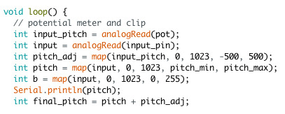
Tumblr media
Using the potentiometer, I am now able to switch between longer notes and really short notes. This creates a whole lot of new possibilities in using my project as a tool in music creation.
I can now use the really short sounds which are lower in pitch and process the sounds through Ableton and create percussive sounds, such as a kick drum. The longer tones on the other hand are more drone-like. The variety of sounds that can be created makes the instrument more interesting to play/perform with and the random-ness in which the pitches are created definitely adds to the fun while improvising. 
1 note · View note
synthtaxerror-blog · 7 years ago
Text
Arduino Final Assignment #1- The Proposal
Writing is one of the earliest and richest forms of communication. We live in an age where we produce large volumes of writing through different mediums such as print, and digital platforms such as the Internet and our mobile devices. As writing is an expressive process guided and adapted by thoughts that evolve over time, the writing process often includes improvisational aspects that resemble music performances. However, traditionally there is a separation between the process of writing and how written results are presented to an audience. At the highest level, a piece of writing tends to be presented to the readers is rather in a linear fashion.
Tumblr media
I’ve been really interested in the idea of transforming creative writing and drawing into a real- time performing art. I feel that the rhythm and pace of writing can be a powerful dimension for expressive writing. A writer’s cognitive and emotional state such as contemplation and hesitation can emerge during writing. Deploying such expression in the process of writing is similar to choreographed visuals and organized sound in an audiovisual performance. My concept to achieving this is to be able to draw and create sound with each stroke. Not only will you be able to enjoy written text after it is presented, you can also enjoy the process and create another form of artistic expression through music. Therefore, this proposal will discuss the influences behind my proposed idea and also explain how I intend to go about bringing my concept to life.
Tumblr media
I was really blown away by Marion Pinaffo & Raphaël Pluvinage’s Papier Machine series that I saw in the learning portal. It was such a brilliant idea to explore electronic circuits in such a fun way. More specifically, I am interested in their project titled Writing Track. Writing track is a piece of paper that has a line on it, which is drawn using a graphite pencil. Whenever a marble passes the graphite pencil line, a sound is produced.
From this project, I inferred that when you touch a conductive object, you create a certain degree of capacitance. This increases the ability of the conductive material you touched (such as graphite) to store a charge. In the context of Arduino, I believe that the board can therefore measure the resistance between the graphite pencil line and for example a paper clip, which could then convert it into a pitch. As you draw or move your pencil across a graphite drawing, the pitches will start to form. I can create a cheap capacitive sensor using the pencil and a paper clip for the project. I could also add something like a potentiometer to further control and vary the pitches that are formed.
Materials List (Tentative)
Musical Pencil
1) Arduino 2) Speaker 3) Potentiometer 4) LED 5) 10k resistor 6) Wires 7) Pencil 8) Paper clip 9) Tape, Heat shrink, or anything to hold the wire to the pencil 10) Breadboard 11) Graphite Paper
Distance Sensor Instrument
1. Arduino Uno + Breadboard+ Jumper Wires 2. Push Button 3. Ping Sensor
SKETCH OF DRAFT CONCEPT:
Tumblr media
Excited to embark on the journey to bring my idea to life! I know it is not going to be easy but I believe this journey will be a fruitful and fun one.
1 note · View note
synthtaxerror-blog · 7 years ago
Text
Arduino Mini Project
Here are the Hi-res pictures of me and Deon’s creation!
Materials Used:
1x Arduino Uno
2x DC motor
2x Wood strips
2x Cable-tie
1x Sandpaper
1x Nail
1x Plastic Bag
1x Breadboard with Jumper Wires
Bunch of Paper Clips
Tumblr media Tumblr media Tumblr media Tumblr media Tumblr media Tumblr media Tumblr media Tumblr media
1 note · View note
synthtaxerror-blog · 7 years ago
Text
Arduino Final Assignment #7- Final Outcomes
Tumblr media
I added an output jack to my Arduino project so that I can route my tones to Ableton for further processing. I also decided to do a new sketch for me to play with, which looked more presentable. 
Tumblr media
Swapped the blu-tack for some good ol’ velcro for a cleaner look. 
Tumblr media
Here are the final results!
vimeo
I used a ping-pong delay and added some reverb to the tones. An audio recording of the piece I performed will be up soon. Really pleased with my project so far. Andy suggested that I should probably build a separate housing for my controls (potentiometer/output jack etc.) so that it can be utilised with greater ease. I will be working on this during the holidays and hopefully it will make my instrument even easier to play. That’s all for now! 
Tumblr media
0 notes
synthtaxerror-blog · 7 years ago
Text
Arduino Final Assignment #4- Musical Graphite Pencil Tests
Here is the Circuit Testing in action!
vimeo
First Discovery:
The graphite sketch and circuit works! I have discovered that the parts of the paper that were darker (More graphite), were easier to detect. The pitch also varies depending on the distance of the paperclip to the pencil. The further away the jumper wire/pencil is to the paperclip, the higher the pitch will be and vice versa. 
Problem:
After the results of my first test, It got me thinking again about what my Lecturer Andy said. The tones were getting slightly annoying after a while and I felt that it was because of the speed of the notes being played and the length of the notes. Although it was a nice mess of sound which could actually be used in certain scenarios, I had to create more variations to play with in order to make my project much more exciting to play/perform with. I then proceeded to try and alter the length of the notes in my code.
Updated Code:
Tumblr media
Highlighted code: The first variable is the output where I want to send the tones to. The second variable is the frequency of the tone and the last variable is to change the length of the tone.
vimeo
This was the result of the new code with the graphite pencil. The tones are much shorter and the Arduino board doesn’t read the differences as quickly as before. I will try to add in the potentiometer next! Hopefully it will be able to vary the length of the notes to provide more colour and also act as a performative tool.
0 notes
synthtaxerror-blog · 7 years ago
Text
Arduino Final Assignment #3- Musical Graphite Pencil
After completing my distance sensor instrument, it was time to create my graphite (musical) pencil! 
Main concept: I am trying to create a cheap capacitive sensor using the pencil and a paper clip. My idea is to be able to make sound as you trace your pencil over a drawing or a sketch. I will also add a potentiometer that will vary the pitches as the pencil is traced across the sketches.  
How it works: When you touch a conductive object, you create a certain degree of capacitance. This increases the ability of the conductive material you touched (such as graphite) to store a charge. The resistance between the graphite pencil line and for example a paper clip can be measured by an Arduino, which could then be converted it pitches. As you draw or move your pencil across a graphite drawing, the pitches will start to form. 
Materials used:
1x Arduino Uno (Clone)
1x Graphite Pencil
1x 5 Ohm Speaker
1x Potentiometer
1x 10k resistor
1x Paper clip (Full metal)
1x Tape, Heat shrink, or anything to hold the wire to the pencil 
1x Breadboard
Jumper Wires
Tools used:
Penknife
Soldering iron + Solder
Masking Tape
Computer with Arduino ide
Steps to build the musical pencil:
Tumblr media
1. I used a penknife to cut a hole in the pencil, exposing the graphite lead.
Tumblr media
2. I attached a jumper wire into the slot that I cut in the pencil. I had to make sure the jumper wire touches the graphite lead. 
Tumblr media
3. I soldered a longer cable to the other side of the jumper wire, that is connected to the pencil. This is so that the pencil can stretch across the paper I will be using to make sound. Lastly, I taped the wire so that it will stay in the pencil. 
Tumblr media
4. I soldered a jumper wire to a paperclip. We are done with the building!
Tumblr media
The wires on 9 and 10 are the wires that will be connected to the pencil and paper
Connections:
Arduino Pin 3 ----------> Speaker +
Arduino Pin 5 ----------> LED 
Speaker - ---------------> GND
Potentiometer pin 1 ---> VCC 5v
Potentiometer pin 2 ---> Arduino A0
Potentiometer pin 3 ---> GND
Pencil -------------------> VCC 5v
Paper Clip --------------> A1
Resistor ----------------> A1 and GND
Code:
#define speaker 3 #define led 5 #define pot A0 #define input_pin A1 #define pitch_min 50 #define pitch_max 4978 void setup() {  Serial.begin(9600); } void loop() {  int input_pitch = analogRead(pot);  int input = analogRead(input_pin);  int pitch_adj = map(input_pitch, 0, 1023, -500, 500);  int pitch = map(input, 0, 1023, pitch_min, pitch_max);  int b = map(input, 0, 1023, 0, 255);  analogWrite(led, b);  Serial.println(pitch);  int final_pitch = pitch + pitch_adj;  if(final_pitch > pitch_max){    final_pitch = pitch_max;  }  if(final_pitch < pitch_min){    final_pitch = pitch_min;  } if(final_pitch != pitch_min){    if(pitch != pitch_min){      tone(speaker, final_pitch, 30);    }  }  delay(25); }
Explanation:
The first condition -> if the value of the final pitch is more than the pitch_max, the value of pitch_max becomes the new final pitch value.
Second condition -> if the value of the final pitch is less than pitch_min, the value of pitch_min becomes the new final pitch value.
Third condition -> if the final pitch and pitch value is not the same as pitch_min, Arduino will take the value in final_pitch and output that value.
I will be showing the video of my tests next! I will also be sharing the problems I faced and how I solved them.
0 notes
synthtaxerror-blog · 7 years ago
Video
tumblr
And it works! I decided to change the notes in the array to a double harmonic minor scale just for fun since I played an Arabian-influenced piece for Friday’s ensemble class.
0 notes
synthtaxerror-blog · 7 years ago
Text
Arduino #5- Soldering Lesson
Tumblr media
This week, we went through the basics of soldering and made our own DIY Piezo using the materials Andy gave us. Yes, Im serious. 
Process of how to make your own Piezo:
1. Cut the audio cables to expose the 2 inner cables [brown for power and blue for ground]
2. Solder these inner cables to the 3.5mm adaptor, which had 2 pins; short for power and long for ground. [*Be sure to hook the cables securely before soldering]
Tumblr media
3.  Expose the opposite ends of the audio cable and solder it to the piezo itself. Power to the white portion, and ground to the golden portion. [Remember to not expose the wires too much as it can cause short circuiting]
*One tip to remedy the problem of over exposed wires would be to put some glue around the cables.
5. Apply hot glue to the cable to secure it in place.
6. Hook it up to a mixer and enjoy your new DIY piezo!
Tumblr media
0 notes